EP0243759B1 - Device for covering conduit openings at automatic couplings of railway vehicles - Google Patents
Device for covering conduit openings at automatic couplings of railway vehicles Download PDFInfo
- Publication number
- EP0243759B1 EP0243759B1 EP87105311A EP87105311A EP0243759B1 EP 0243759 B1 EP0243759 B1 EP 0243759B1 EP 87105311 A EP87105311 A EP 87105311A EP 87105311 A EP87105311 A EP 87105311A EP 0243759 B1 EP0243759 B1 EP 0243759B1
- Authority
- EP
- European Patent Office
- Prior art keywords
- band
- section
- conduit opening
- coupling
- serving
- Prior art date
- Legal status (The legal status is an assumption and is not a legal conclusion. Google has not performed a legal analysis and makes no representation as to the accuracy of the status listed.)
- Expired - Lifetime
Links
- 238000010168 coupling process Methods 0.000 title claims abstract description 33
- 230000008878 coupling Effects 0.000 title claims abstract description 29
- 238000005859 coupling reaction Methods 0.000 title claims abstract description 29
- 230000002787 reinforcement Effects 0.000 claims 1
- 230000001681 protective effect Effects 0.000 description 9
- 238000010276 construction Methods 0.000 description 2
- 230000013011 mating Effects 0.000 description 2
- 238000007789 sealing Methods 0.000 description 2
- 230000015572 biosynthetic process Effects 0.000 description 1
- 238000011109 contamination Methods 0.000 description 1
- 238000006073 displacement reaction Methods 0.000 description 1
- 238000005755 formation reaction Methods 0.000 description 1
- 230000035515 penetration Effects 0.000 description 1
Images
Classifications
-
- B—PERFORMING OPERATIONS; TRANSPORTING
- B61—RAILWAYS
- B61G—COUPLINGS; DRAUGHT AND BUFFING APPLIANCES
- B61G5/00—Couplings for special purposes not otherwise provided for
- B61G5/06—Couplings for special purposes not otherwise provided for for, or combined with, couplings or connectors for fluid conduits or electric cables
Definitions
- the invention relates to a device for covering the line mouth at the front end of a line coupling, which is housed in the coupling head of an automatic coupling for rail vehicles, with a longitudinally movable, flexible band, which has a portion serving as a protective flap, which in the uncoupled position of the coupling head in front of the
- the line mouth can be adjusted to cover it and can be removed during coupling processes from the line mouth to release it, the band being guided over at least one deflection point deflecting its longitudinal direction.
- the section of the band which can be adjusted in front of the line mouth as a protective flap in the uncoupled state requires special guidance and / or stiffening in order to be able to cover the line mouth reliably; Special springs and / or rods are required for this guidance or stiffening, which results in a complex and sensitive mechanism.
- the invention has for its object to design a device of the type mentioned in such a way that it avoids the shortcomings of the known devices, is particularly simple and requires little effort.
- the band is provided, at least in the region of its section serving as a protective flap, with an elastic transverse corrugation running transversely to its longitudinal direction, which is flattened in band parts located in the region of deflection points, and in that the serving as a protective flap Section of the tape is stable in front of the line mouth due to inherent rigidity.
- the sufficient inherent rigidity of the band is achieved by the transverse corrugation, which ensures that the band is held securely in front of the pipe mouth, even without special guiding and / or stiffening devices.
- a line coupling I is shown in dash-dotted lines, which belongs to an automatic coupling of the usual type, which is not shown in the remainder, and whose mouth 2, with which it can be coupled to a mating coupling, not shown, faces away from the viewer.
- a section 3 of a flexible band 4 in front of the mouth 2, the section 3 covers dasei the mouth 2 and thus serves as a protective flap for this.
- the deflection point 5 has several bolts 6 between which the band 4 is passed and of a longitudinal extent in its section 3 in which is perpendicular to the axial direction of the line coupling I.
- a longitudinal direction running approximately parallel to and to the side of the line coupling I is deflected.
- the rear end of the band 4 is cut off and not shown; at this end an actuating device engages, by means of which the band can be moved in its longitudinal direction in accordance with the direction of the double arrow 7.
- the actuating device can have actuating levers which, when a mating clutch starts, pull the band 4 backwards against the spring force from the position shown until the section 3 slides off the mouth 2 and thus releases the latter for coupling. When uncoupling, the actuating levers are released from the counter clutch, and the spring force mentioned can advance the band 4 again into the position shown.
- the actuating device can therefore be designed as shown in the aforementioned DE-A 3 435 779.
- section 3 can be guided through the deflection point 5 in front of the mouth 2 and that no further guiding and / or stiffening devices are required for section 3; section 3 is thus held in front of mouth 2 by its inherent rigidity.
- band 4 In order to give the band 4 the required inherent rigidity, it must be designed at least in the region of its section 3 serving as a protective flap, as described below:
- the band 4 is provided, at least in the region of its section 3, with a transverse corrugation which is elastic or molded into the band 4; the transverse corrugation is illustrated in FIG. 2 with the reference number 8 by reference to the locations of its maximum, lateral and in the longitudinal direction of the band 4 shaped formations.
- the transverse corrugation 8 is formed from the band 4, i.e. the band 4 is flattened in the region of the deflection point 5 by the bolts 6, as indicated in Fig.l; as a result, the longitudinal direction of the band 4 in the deflection point 5 can be deflected easily. Outside the deflection point 5, the band 4 automatically resumes the transverse corrugation 8 due to its elasticity.
- the section of the band 4 that is currently in the deflection point 5 is flattened, while the band sections adjoining the deflection point 5 on both sides automatically wave transversely again.
- the transverse corrugation 8 runs between lateral delimitation planes 9 and 10, and the lateral ones Edges II and 12 of the band 4 are located between the boundary planes 9 and 10 approximately in their central plane 13, the distances a and b of the edges II and 12 to the boundary planes 9 and 10 are thus approximately the same.
- the arches of the transverse corrugation 8 are designated in FIG. 3 with the reference numbers 14, 15 and 16. It is expedient if the edges II and 12 of the band 4 lie in arc sections 14 and 16 directed away from the mouth 2. This design prevents the edges 11 or 12 from coming into contact with the mouth 2 and damaging the sealing ring.
- the band 4 has the transverse corrugation 8 at least in the region of its section 3 which can be moved as a cover flap in front of the mouth 2.
- care must be taken to ensure that the band 4 has a reduced inherent rigidity in its area facing away from the section, that is to say it could buckle against the mouth 2 without any special precautions in particular when the section 3 is pushed forward.
- the band 4 can also be provided with the transverse corrugation 4 over its entire length, as a result of which it obtains an inherent rigidity in all of its regions located outside the deflection point 5, which it automatically stretches and thus also holds suitable for transmitting thrust forces.
- the band 4 can also be deflected several times, it is only essential that the deflection point 5, which is located on the side of the mouth 2, directs and guides the section 3 in front of the mouth 2, the section 3 thus no further guidance or stiffening is required.
- the deflection point 5 may josei or the like instead of the bolt 6 with rollers. be provided, whereby the longitudinal displacement of the belt 4 is facilitated.
- the device for covering the line mouth (2) at the front end of a line coupling (I) has a longitudinally movable, flexible band (4), a section (3) of the band (4) serving as a protective flap in the uncoupled state in front of the line mouth (2 ) is adjustable.
- the band (4) is provided at least in its section (3) with a transverse corrugation (8), by means of which it can be held in front of the mouth (2) with inherent rigidity.
- the transverse corrugation (8) is flattened in a deflection point (5).
Landscapes
- Engineering & Computer Science (AREA)
- Mechanical Engineering (AREA)
- Clamps And Clips (AREA)
- Package Frames And Binding Bands (AREA)
- Quick-Acting Or Multi-Walled Pipe Joints (AREA)
- Guiding Agricultural Machines (AREA)
Abstract
Description
Die Erfindung betrifft eine Vorrichtung zum Abdecken der Leitungsmündung am vorderen Ende einer Leitungskupplung, die im Kupplungskopf einer selbsttätigen Kupplung für Schienenfahrzeuge untergebracht ist, mit einem längsbeweglich geführten, flexiblen Band, welches einen als Schutzklappe dienenden Abschnitt aufweist, welcher in ungekuppelter Stellung des Kupplungskopfes vor die Leitungsmündung zu deren Abdeckung einstellbar und während Kupplungsvorgängen von der Leitungsmündung zu deren Freigabe entfernbar ist, wobei das Band über wenigstens eine seine Längsrichtung umlenkende Umlenkstelle geführt ist.The invention relates to a device for covering the line mouth at the front end of a line coupling, which is housed in the coupling head of an automatic coupling for rail vehicles, with a longitudinally movable, flexible band, which has a portion serving as a protective flap, which in the uncoupled position of the coupling head in front of the The line mouth can be adjusted to cover it and can be removed during coupling processes from the line mouth to release it, the band being guided over at least one deflection point deflecting its longitudinal direction.
Zum Abdecken der Mündungen von Leitungskupplungen an selbsttätigen Kupplungen von Schienenfahrzeugen, welche dem Verhindern des Eindringens von Fremdkörpern, insbesondere Verschmutzung, in das Druckluftsystem der Schienenfahrzeuge und/oder dem berührungs- und verschmutzungssicheren Abdecken von elektrischen Kupplungskontakten dienen, sind bereits vielfältige Konstruktionen bekannt. Viele dieser Konstruktionen weisen beispielsweise der DE-A 2 043 913 entsprechende Schwenkklappen auf, welche durch Federkraft vor die Leitungsmündung schwenkbar und während Kupplungsvorgängen durch Anlaufen des Gegenkupplungskopfes gegen Betätigungshebel wegschwenkbar sind. Diese Konstruktionen sind jedoch aufwendig.A variety of constructions are already known for covering the mouths of line couplings on automatic couplings of rail vehicles, which serve to prevent the penetration of foreign bodies, in particular dirt, into the compressed air system of the rail vehicles and / or to protect electrical coupling contacts from contact and contamination. Many of these constructions have, for example, DE-A 2 043 913 corresponding swivel flaps which can be swiveled by spring force in front of the pipe mouth and swiveled away against actuating levers during coupling processes by the counter coupling head starting up. However, these designs are complex.
Zum Vereinfachen ist für eine den eingangs genannten Merkmalen entsprechende Vorrichtung mit der DE-A 3 435 779 ( & EP-A 0 175 884) bereits vorgeschlagen worden, als Schutzklappe ein flexibles Band vorzusehen, dessen einer Endbereich in ungekuppeltem Zustand vor die Mündung der Leitungskupplung führbar ist. Das Band wird seitlich der Leitungsmündung umgelenkt, so daß es eine etwa parallel zur Leitungskupplung verlaufende Längsrichtung erfährt. Die Längsbewegung des Bandes erfolgt in Abdeckrichtung vor die Leitungsmündung durch Federkraft und entgegengesetzt durch Anlaufen der Gegenkupplung gegen Betätigungshebel. Bei dieser an sich bereits recht einfachen Vorrichtung bedarf der als Schutzklappe im ungekuppelten Zustand vor die Leitungsmündung einstellbare Abschnitt des Bandes einer besonderen Führung und/oder Versteifung, um die Leitungsmündung sicher abdecken zu können; zu dieser Führung bzw. Versteifung sind besondere Federn und/oder Stäbe erforderlich, wodurch sich eine aufwendige und empfindliche Mechanik ergibt.For simplification, it has already been proposed for a device corresponding to the features mentioned at the beginning with DE-A 3 435 779 (& EP-A 0 175 884) to provide a flexible band as a protective flap, one end region of which is in the uncoupled state in front of the mouth of the line coupling is feasible. The band is deflected to the side of the line mouth, so that it experiences a longitudinal direction running approximately parallel to the line coupling. The longitudinal movement of the belt takes place in the direction of covering in front of the pipe mouth by spring force and in the opposite direction by the counter coupling against the actuating lever. In this device, which in itself is quite simple, the section of the band which can be adjusted in front of the line mouth as a protective flap in the uncoupled state requires special guidance and / or stiffening in order to be able to cover the line mouth reliably; Special springs and / or rods are required for this guidance or stiffening, which results in a complex and sensitive mechanism.
Der Erfindung liegt die Aufgabe zugrunde, eine Vorrichtung der eingangs genannten Art derart auszubilden, daß sie die Mängel der bekannten Vorrichtungen vermeidet, insbesondere einfach ist und geringen Aufwand erfordert.The invention has for its object to design a device of the type mentioned in such a way that it avoids the shortcomings of the known devices, is particularly simple and requires little effort.
Diese Aufgabe wird nach der Erfindung dadurch gelöst, daß das Band zumindest im Bereich seines als Schutzklappe dienenden Abschnittes mit einer quer zu seiner Längsrichtung verlaufenden, elastischen Querwellung versehen ist, welche in im Bereich von Umlenkstellen befindlichen Bandteilen flachgedrückt ist, und daß der als Schutzklappe dienende Abschnitt des Bandes durch Eigensteifigkeit vor der Leitungsmündung haltbar ist. Die ausreichende Eigensteifigkeit des Bandes wird hierbei durch die Querwellung erzielt, sie gewährleistet eine sichere Halterung des Bandes vor der Leitungsmündung auch ohne besondere Führungs- und/oder Versteifungsvorrichtungen.This object is achieved according to the invention in that the band is provided, at least in the region of its section serving as a protective flap, with an elastic transverse corrugation running transversely to its longitudinal direction, which is flattened in band parts located in the region of deflection points, and in that the serving as a protective flap Section of the tape is stable in front of the line mouth due to inherent rigidity. The sufficient inherent rigidity of the band is achieved by the transverse corrugation, which ensures that the band is held securely in front of the pipe mouth, even without special guiding and / or stiffening devices.
Dabei ergibt sich nach der weiteren Erfindung eine besonders einfache Anordnung, wenn der als Schutzklappe dienende Abschnitt des Bandes von der seitlich der Leitungsmündung befindlichen Umlenkstelle ohne weitere Führungs- und/oder Versteifungsvorrichtungen vor die Leitungsmündung führbar ist.According to the further invention, this results in a particularly simple arrangement if the section of the band serving as a protective flap can be guided in front of the line mouth from the deflection point located on the side of the line mouth without further guiding and / or stiffening devices.
Die nach der weiteren Erfindung zweckmäßige und vorteilhafte Ausgestaltung der Vorrichtung ist den weiteren Unteransprüchen entnehmbar.The useful and advantageous embodiment of the device according to the further invention can be found in the further subclaims.
In der Zeichnung ist ein Ausführungsbeispiel für eine nach der Erfindung ausgebildete Vorrichtung dargestellt und zwar zeigt
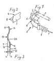
- Figur I schematisch eine Gesamtanordnung in den für die Erfindung wesentlichen Teilen,
- Figur 2 einen Ausschnitt aus dem Band in vergrößertem Maßstab und
- Figur 3 einen Querschnitt durch das Band in nochmals vergrößertem Maßstab.
- FIG. 1 schematically shows an overall arrangement in the parts essential for the invention,
- Figure 2 shows a section of the tape on an enlarged scale and
- Figure 3 shows a cross section through the band on a further enlarged scale.
In Fig.1 ist strichpunktiert eine Leitungskupplung I dargestellt, welche einer im übrigen nicht gezeigten, selbsttätigen Kupplung üblicher Bauart zugehört und deren Mündung 2, mit welcher sie mit einer nicht dargestellten Gegenkupplung kuppelbar ist, dem Betrachter abgewandt ist. Im dargestellten, ungekuppelten Zustand befindet sich vor der Mündung 2 ein Abschnitt 3 eines flexiblen Bandes 4, der Abschnitt 3 deckt daßei die Mündung 2 ab und dient somit für diese als Schutzklappe. Seitlich der Mündung 2 befindet sich an der Kupplung eine Umlenkstelle 5 für das Band 4, die Umlenkstelle 5 weist daßei mehrere Bolzen 6 auf, zwischen welchen das Band 4 hindurchgeführt ist und von einer senkrecht zur Achsrichtung der Leitungskupplung I verlaufenden Längserstreckung in seinem Abschnitt 3 in eine etwa parallel zur und seitlich der Leitungskupplung I nach rückwärts verlaufende Längsrichtung umgelenkt wird. Das rückwärtige Ende des Bandes 4 ist abgeschnitten und nicht dargestellt; an diesem Ende greift eine Betätigungsvorrichtung an, mittels welcher das Band in seiner Längsrichtung entsprechend der Richtung des Doppelpfeiles 7 bewegbar ist. Die nicht dargestellte Betätigungsvorrichtung kann Betätigungshebel aufweisen, welche bei Anlaufen einer Gegenkupplung das Band 4 aus der dargestellten Lage entgegen Federkraft nach rückwärts zurückziehen, bis der Abschnitt 3 von der Mündung 2 abgleitet und letztere somit zum Kuppeln freigibt. Beim Entkuppeln werden die Betätigungshebel von der Gegenkupplung freigegeben, und die erwähnte Federkraft vermag das Band 4 wieder in die dargestellte Stellung vorzuschieben. Die Betätigungsvorrichtung kann also eine Ausbildung erhalten, wie sie in der bereits erwähnten DE-A 3 435 779 gezeigt ist.In FIG. 1, a line coupling I is shown in dash-dotted lines, which belongs to an automatic coupling of the usual type, which is not shown in the remainder, and whose mouth 2, with which it can be coupled to a mating coupling, not shown, faces away from the viewer. In the illustrated, uncoupled state, there is a section 3 of a
Aus Fig.1 ist ersichtlich, daß der Abschnitt 3 allein durch die Umlenkstelle 5 vor die Mündung 2 führbar ist und daß keine weiteren Führungs-und/oder Versteifungsvorrichtungen für den Abschnitt 3 erforderlich sind; der Abschnitt 3 wird also durch seine Eigensteifigkeit vor der Mündung 2 gehalten. Um dem Band 4 die erforderliche Eigensteifigkeit zu verleihen, ist dieses zumindest im Bereich seines als Schutzklappe dienenden Abschnittes 3, wie nachfolgend beschrieben, auszubilden:It can be seen from FIG. 1 that section 3 can be guided through the
Gemäß Fig.2 ist das Band 4 zumindest im Bereich seines Abschnittes 3 mit einer Querwellung versehen, welche elastisch ausgebildet bzw. in das Band 4 eingeformt ist; die Querwellung ist in Fig.2 mit der Bezugszahl 8 durch Hinweis auf die Stellen ihrer maximalen, seitlichen und in Längsrichtung des Bandes 4 verlaufenden Ausformungen verdeutlicht. Im Bereich der Umlenkstelle 5 wird die Querwellung 8 aus dem Band 4 ausgeformt, d.h. das Band 4 wird im Bereich der Umlenkstelle 5 durch die Bolzen 6 flachgedrückt, wie es in Fig.l angedeutet ist; hierdurch ist die Längsrichtung des Bandes 4 in der Umlenkstelle 5 gut umlenkbar. Außerhalb der Umlenkstelle 5 nimmt das Band 4 durch seine Elastizität selbsttätig wieder die Querwellung 8 an. Beim Verschieben des Bandes 4 in seiner Längsrichtung durch die Umlenkstelle 5 wird jeweils der gerade in der Umlenkstelle 5 befindliche Abschnitt des Bandes 4 flachgedrückt, während die sich beidseitig an die Umlenkstelle 5 anschließenden Bandabschnitte wieder selbsttätig quer wellen.According to FIG. 2, the
An der Mündung 2 der Leitungskupplung I befindet sich ein empfindlicher Dichtring, welcher insbesondere bei Berührung mit scharfen Kanten leicht beschädigt werden kann. Um derartige, beschädigungsträchtige Berührungen zu vermeiden, ist es zweckmäßig, den Querschnitt des Bandes 4 in seinem gewellten Bereich, also insbesondere im Abschnitt 3, gemäß Fig.3 zu gestalten: Die Querwellung 8 verläuft daßei zwischen seitlichen Begrenzungsebenen 9 und 10, und die seitlichen Ränder II und 12 des Bandes 4 befinden sich zwischen den Begrenzungsebenen 9 und 10 etwa in deren Mittelebene 13, die Abstände a und b der Ränder II und 12 zu den Begrenzungsebenen 9 und 10 sind somit also annähernd gleich. Die Bögen der Querwellung 8 sind in Fig. 3 mit den Bezugszahlen 14,15 und 16 bezeichnet. Es ist zweckmäßig, wenn die Ränder II und 12 des Bandes 4 in von der Mündung 2 weggerichteten Bogenabschnitten 14 und 16 liegen. Durch diese Ausbildung ist ausgeschlossen, daß die Ränder 11 oder 12 mit der Mündung 2 in Berührung kommen und deren Dichtring beschädigen können.At the mouth 2 of the line coupling I there is a sensitive sealing ring, which can be easily damaged, especially when it comes into contact with sharp edges. In order to avoid such damage-prone contact, it is advisable to design the cross section of the
Es ist wesentlich, daß, wie bereits erwähnt, das Band 4 die Querwellung 8 wenigstens im Bereich seines als Abdeckklappe vor die Mündung 2 bewegbaren Abschnittes 3 aufweist. Bei dieser Ausführung ist darauf zu achten, daß das Band 4 in seinem dem Abschnitt abgewandten Bereich eine verminderte Eigensteifigkeit aufweist, es also insbesondere bei Schubbelastung zum Vorschieben des Abschnittes 3 vor die Mündung 2 ohne besondere Vorkehrungen hiergegen ausknicken könnte. Abweichend hierzu kann das Band 4 jedoch auch auf seiner gesamten Länge mit der Querwellung 4 versehen sein, wodurch es in allen seinen außerhalb der Umlenkstelle 5 befindlichen Bereichen eine Eigensteifigkeit erhält, die es selbsttätig gestreckt und damit auch zum Übertragen von Schubkräften geeignet hält.It is essential that, as already mentioned, the
Abweichend zu vorstehend beschriebener Ausführungsform kann das Band 4 auch mehrfach umgelenkt werden, es ist lediglich wesentlich, daß diejenige Umlenkstelle 5, welche sich seitlich der Mündung 2 befindet, den Abschnitt 3 vor die Mündung 2 lenkt und führt, der Abschnitt 3 somit keiner weiteren Führung oder Versteifung bedarf. Die Umlenkstelle 5 kann daßei anstelle der Bolzen 6 auch mit Rollen o.dgl. versehen sein, wodurch die Längsverschiebung des Bandes 4 erleichtert wird.Deviating from the embodiment described above, the
Die Vorrichtung zum Abdecken der Leitungsmündung (2) am vorderen Ende einer Leitungskupplung (I) weist ein längsbewegliches, flexibles Band (4) auf, wobei ein als Schutzklappe dienender Abschnitt (3) des Bandes (4) im ungekuppelten Zustand vor die Leitungsmündung (2) einstellbar ist.The device for covering the line mouth (2) at the front end of a line coupling (I) has a longitudinally movable, flexible band (4), a section (3) of the band (4) serving as a protective flap in the uncoupled state in front of the line mouth (2 ) is adjustable.
Das Band (4) ist zumindest in seinem Abschnitt (3) mit einer Querwellung (8) versehen, durch welche es unter Eigensteifigkeit vor der Mündung (2) haltbar ist. Zur Umlenkung der Längsrichtung des Bandes (4) wird die Querwellung (8) in einer Umlenkstelle (5) flachgedrückt.The band (4) is provided at least in its section (3) with a transverse corrugation (8), by means of which it can be held in front of the mouth (2) with inherent rigidity. To deflect the longitudinal direction of the belt (4), the transverse corrugation (8) is flattened in a deflection point (5).
- I LeitungskupplungI line coupling
- 2 Mündung2 mouth
- 3 Abschnitt3 section
- 4 Band4 volume
- 5 Umlenkstelle5 deflection point
- 6 Bolzen6 bolts
- 7 Doppelpfeil7 double arrow
- 8 Querwellung8 cross corrugation
- 9 Begrenzungsebene9 boundary plane
- 10 Begrenzungsebene10 boundary plane
- II RandII margin
- 12 Rand12 rand
- 13 Mittelebene13 middle level
- 14 Bogen14 sheets
- 15 Bogen15 sheets
- 16 Bogen16 sheets
- a Abstanda distance
- b Abstandb distance
Claims (6)
Priority Applications (1)
| Application Number | Priority Date | Filing Date | Title |
|---|---|---|---|
| AT87105311T ATE49389T1 (en) | 1986-05-02 | 1987-04-10 | DEVICE FOR COVERING LINE MOUTINGS ON AUTOMATIC COUPLINGS OF RAILWAY VEHICLES. |
Applications Claiming Priority (2)
| Application Number | Priority Date | Filing Date | Title |
|---|---|---|---|
| DE3614876 | 1986-05-02 | ||
| DE3614876 | 1986-05-02 |
Publications (3)
| Publication Number | Publication Date |
|---|---|
| EP0243759A2 EP0243759A2 (en) | 1987-11-04 |
| EP0243759A3 EP0243759A3 (en) | 1988-04-20 |
| EP0243759B1 true EP0243759B1 (en) | 1990-01-10 |
Family
ID=6300012
Family Applications (1)
| Application Number | Title | Priority Date | Filing Date |
|---|---|---|---|
| EP87105311A Expired - Lifetime EP0243759B1 (en) | 1986-05-02 | 1987-04-10 | Device for covering conduit openings at automatic couplings of railway vehicles |
Country Status (4)
| Country | Link |
|---|---|
| EP (1) | EP0243759B1 (en) |
| AT (1) | ATE49389T1 (en) |
| DD (1) | DD269591A5 (en) |
| DE (1) | DE3761365D1 (en) |
Families Citing this family (1)
| Publication number | Priority date | Publication date | Assignee | Title |
|---|---|---|---|---|
| CN113353117B (en) * | 2021-07-19 | 2025-02-11 | 中车眉山车辆有限公司 | A connecting sealing structure of an automatic coupler gas circuit connector |
Family Cites Families (1)
| Publication number | Priority date | Publication date | Assignee | Title |
|---|---|---|---|---|
| DE3435779A1 (en) * | 1984-09-28 | 1986-04-10 | Knorr-Bremse, 1000 Berlin und 8000 München | DEVICE FOR COVERING MOUTHS OF LINES IN AUTOMATIC COUPLINGS OF RAIL VEHICLES |
-
1987
- 1987-04-10 EP EP87105311A patent/EP0243759B1/en not_active Expired - Lifetime
- 1987-04-10 AT AT87105311T patent/ATE49389T1/en not_active IP Right Cessation
- 1987-04-10 DE DE8787105311T patent/DE3761365D1/en not_active Expired - Lifetime
- 1987-04-30 DD DD87302296A patent/DD269591A5/en not_active IP Right Cessation
Also Published As
| Publication number | Publication date |
|---|---|
| EP0243759A3 (en) | 1988-04-20 |
| DD269591A5 (en) | 1989-07-05 |
| ATE49389T1 (en) | 1990-01-15 |
| DE3761365D1 (en) | 1990-02-15 |
| EP0243759A2 (en) | 1987-11-04 |
Similar Documents
| Publication | Publication Date | Title |
|---|---|---|
| DE3852766T3 (en) | Device for inserting a cable into a cable sheath protection tube. | |
| EP0379655B1 (en) | Connection device | |
| DE2635269C3 (en) | Device for connecting the ends of two pipes | |
| DE19618316C2 (en) | Device for spreading concrete | |
| DE2240274C3 (en) | Remote-controlled steering device for vehicles | |
| DE3710922C1 (en) | Pliers for moving flexible strand material | |
| EP0243759B1 (en) | Device for covering conduit openings at automatic couplings of railway vehicles | |
| DE1551569A1 (en) | Method and device for pressurizing pipe sections | |
| EP0656449A2 (en) | Device especially for working on channels | |
| EP0266630B1 (en) | Apparatus for sucking-off fibre material | |
| DE2008869A1 (en) | Automatic connection device for operating lines on rail vehicle couplings | |
| EP0150236B1 (en) | Connection for a pressure pipe | |
| EP0229087A1 (en) | Flexible hose | |
| DE19502515C2 (en) | Exhaust suction hose with disconnection device | |
| DE2219684C3 (en) | Pipeline coupling for a central buffer coupling of rail vehicles | |
| DE1947189A1 (en) | Device for connecting train lines | |
| AT523559B1 (en) | Weather protection for electrical connection points | |
| DE2246740C3 (en) | Arrangement for moving out test bars and remaining lengths of rolling stock of various profile cross-sections from the rolling line of wire and / or fine steel lines | |
| DE3127758C2 (en) | Device for connecting flanged plastic pipes | |
| DE2737136A1 (en) | CUFF | |
| DE1455228B2 (en) | Automatic coupling for railway vehicles | |
| DE3417725C1 (en) | Fastening device for a switch housing on a spar | |
| EP0238436B1 (en) | Driving mechanism for a loop car | |
| DE3125656C2 (en) | "Device for connecting two pipe ends" | |
| DE1157151B (en) | Braking device for pneumatic tubes |
Legal Events
| Date | Code | Title | Description |
|---|---|---|---|
| PUAI | Public reference made under article 153(3) epc to a published international application that has entered the european phase |
Free format text: ORIGINAL CODE: 0009012 |
|
| AK | Designated contracting states |
Kind code of ref document: A2 Designated state(s): AT BE CH DE FR IT LI SE |
|
| PUAL | Search report despatched |
Free format text: ORIGINAL CODE: 0009013 |
|
| AK | Designated contracting states |
Kind code of ref document: A3 Designated state(s): AT BE CH DE FR IT LI SE |
|
| 17P | Request for examination filed |
Effective date: 19880316 |
|
| 17Q | First examination report despatched |
Effective date: 19890615 |
|
| GRAA | (expected) grant |
Free format text: ORIGINAL CODE: 0009210 |
|
| AK | Designated contracting states |
Kind code of ref document: B1 Designated state(s): AT BE CH DE FR IT LI SE |
|
| REF | Corresponds to: |
Ref document number: 49389 Country of ref document: AT Date of ref document: 19900115 Kind code of ref document: T |
|
| ITF | It: translation for a ep patent filed | ||
| REF | Corresponds to: |
Ref document number: 3761365 Country of ref document: DE Date of ref document: 19900215 |
|
| ET | Fr: translation filed | ||
| RAP2 | Party data changed (patent owner data changed or rights of a patent transferred) |
Owner name: UNICUPLER GMBH |
|
| REG | Reference to a national code |
Ref country code: CH Ref legal event code: PUE Owner name: UNICUPLER GMBH |
|
| ITPR | It: changes in ownership of a european patent |
Owner name: CESSIONE;UNICUPLER GMBH |
|
| PLBE | No opposition filed within time limit |
Free format text: ORIGINAL CODE: 0009261 |
|
| STAA | Information on the status of an ep patent application or granted ep patent |
Free format text: STATUS: NO OPPOSITION FILED WITHIN TIME LIMIT |
|
| REG | Reference to a national code |
Ref country code: FR Ref legal event code: TP |
|
| 26N | No opposition filed | ||
| ITTA | It: last paid annual fee | ||
| EAL | Se: european patent in force in sweden |
Ref document number: 87105311.2 |
|
| REG | Reference to a national code |
Ref country code: CH Ref legal event code: PUE Owner name: UNICUPLER GMBH |
|
| REG | Reference to a national code |
Ref country code: FR Ref legal event code: TP |
|
| PGFP | Annual fee paid to national office [announced via postgrant information from national office to epo] |
Ref country code: FR Payment date: 20060420 Year of fee payment: 20 |
|
| PGFP | Annual fee paid to national office [announced via postgrant information from national office to epo] |
Ref country code: SE Payment date: 20060424 Year of fee payment: 20 Ref country code: AT Payment date: 20060424 Year of fee payment: 20 |
|
| PGFP | Annual fee paid to national office [announced via postgrant information from national office to epo] |
Ref country code: CH Payment date: 20060425 Year of fee payment: 20 |
|
| PGFP | Annual fee paid to national office [announced via postgrant information from national office to epo] |
Ref country code: BE Payment date: 20060426 Year of fee payment: 20 |
|
| PGFP | Annual fee paid to national office [announced via postgrant information from national office to epo] |
Ref country code: IT Payment date: 20060430 Year of fee payment: 20 |
|
| PGFP | Annual fee paid to national office [announced via postgrant information from national office to epo] |
Ref country code: DE Payment date: 20060626 Year of fee payment: 20 |
|
| REG | Reference to a national code |
Ref country code: CH Ref legal event code: PL |
|
| EUG | Se: european patent has lapsed | ||
| BE20 | Be: patent expired |
Owner name: *KNORR-BREMSE A.G. Effective date: 20070410 Owner name: *UNICUPLER G.M.B.H. Effective date: 20070410 |