EP0243745A1 - Pyrotechnic dowel - Google Patents
Pyrotechnic dowel Download PDFInfo
- Publication number
- EP0243745A1 EP0243745A1 EP87105171A EP87105171A EP0243745A1 EP 0243745 A1 EP0243745 A1 EP 0243745A1 EP 87105171 A EP87105171 A EP 87105171A EP 87105171 A EP87105171 A EP 87105171A EP 0243745 A1 EP0243745 A1 EP 0243745A1
- Authority
- EP
- European Patent Office
- Prior art keywords
- pyrotechnic
- detonator
- dowel
- longitudinal channel
- deformation space
- Prior art date
- Legal status (The legal status is an assumption and is not a legal conclusion. Google has not performed a legal analysis and makes no representation as to the accuracy of the status listed.)
- Ceased
Links
- 239000002360 explosive Substances 0.000 claims abstract description 10
- 230000001960 triggered effect Effects 0.000 claims abstract description 3
- 230000035939 shock Effects 0.000 claims description 2
- 239000002775 capsule Substances 0.000 abstract description 6
- 238000004873 anchoring Methods 0.000 description 2
- 230000000694 effects Effects 0.000 description 2
- 238000010438 heat treatment Methods 0.000 description 2
- 230000006698 induction Effects 0.000 description 2
- 238000009413 insulation Methods 0.000 description 2
- 239000002184 metal Substances 0.000 description 2
- 239000007787 solid Substances 0.000 description 2
- 238000002604 ultrasonography Methods 0.000 description 2
- 108091092889 HOTTIP Proteins 0.000 description 1
- 238000005474 detonation Methods 0.000 description 1
- 238000007373 indentation Methods 0.000 description 1
- 230000001939 inductive effect Effects 0.000 description 1
- 239000000463 material Substances 0.000 description 1
- 239000000203 mixture Substances 0.000 description 1
- 230000002093 peripheral effect Effects 0.000 description 1
- 238000005476 soldering Methods 0.000 description 1
Images
Classifications
-
- F—MECHANICAL ENGINEERING; LIGHTING; HEATING; WEAPONS; BLASTING
- F16—ENGINEERING ELEMENTS AND UNITS; GENERAL MEASURES FOR PRODUCING AND MAINTAINING EFFECTIVE FUNCTIONING OF MACHINES OR INSTALLATIONS; THERMAL INSULATION IN GENERAL
- F16B—DEVICES FOR FASTENING OR SECURING CONSTRUCTIONAL ELEMENTS OR MACHINE PARTS TOGETHER, e.g. NAILS, BOLTS, CIRCLIPS, CLAMPS, CLIPS OR WEDGES; JOINTS OR JOINTING
- F16B13/00—Dowels or other devices fastened in walls or the like by inserting them in holes made therein for that purpose
-
- F—MECHANICAL ENGINEERING; LIGHTING; HEATING; WEAPONS; BLASTING
- F16—ENGINEERING ELEMENTS AND UNITS; GENERAL MEASURES FOR PRODUCING AND MAINTAINING EFFECTIVE FUNCTIONING OF MACHINES OR INSTALLATIONS; THERMAL INSULATION IN GENERAL
- F16B—DEVICES FOR FASTENING OR SECURING CONSTRUCTIONAL ELEMENTS OR MACHINE PARTS TOGETHER, e.g. NAILS, BOLTS, CIRCLIPS, CLAMPS, CLIPS OR WEDGES; JOINTS OR JOINTING
- F16B19/00—Bolts without screw-thread; Pins, including deformable elements; Rivets
- F16B19/04—Rivets; Spigots or the like fastened by riveting
- F16B19/08—Hollow rivets; Multi-part rivets
- F16B19/12—Hollow rivets; Multi-part rivets fastened by fluid pressure, including by explosion
- F16B19/125—Hollow rivets; Multi-part rivets fastened by fluid pressure, including by explosion fastened by explosion
-
- F—MECHANICAL ENGINEERING; LIGHTING; HEATING; WEAPONS; BLASTING
- F16—ENGINEERING ELEMENTS AND UNITS; GENERAL MEASURES FOR PRODUCING AND MAINTAINING EFFECTIVE FUNCTIONING OF MACHINES OR INSTALLATIONS; THERMAL INSULATION IN GENERAL
- F16B—DEVICES FOR FASTENING OR SECURING CONSTRUCTIONAL ELEMENTS OR MACHINE PARTS TOGETHER, e.g. NAILS, BOLTS, CIRCLIPS, CLAMPS, CLIPS OR WEDGES; JOINTS OR JOINTING
- F16B37/00—Nuts or like thread-engaging members
- F16B37/12—Nuts or like thread-engaging members with thread-engaging surfaces formed by inserted coil-springs, discs, or the like; Independent pieces of wound wire used as nuts; Threaded inserts for holes
- F16B37/122—Threaded inserts, e.g. "rampa bolts"
-
- F—MECHANICAL ENGINEERING; LIGHTING; HEATING; WEAPONS; BLASTING
- F42—AMMUNITION; BLASTING
- F42B—EXPLOSIVE CHARGES, e.g. FOR BLASTING, FIREWORKS, AMMUNITION
- F42B3/00—Blasting cartridges, i.e. case and explosive
- F42B3/006—Explosive bolts; Explosive actuators
-
- Y—GENERAL TAGGING OF NEW TECHNOLOGICAL DEVELOPMENTS; GENERAL TAGGING OF CROSS-SECTIONAL TECHNOLOGIES SPANNING OVER SEVERAL SECTIONS OF THE IPC; TECHNICAL SUBJECTS COVERED BY FORMER USPC CROSS-REFERENCE ART COLLECTIONS [XRACs] AND DIGESTS
- Y10—TECHNICAL SUBJECTS COVERED BY FORMER USPC
- Y10S—TECHNICAL SUBJECTS COVERED BY FORMER USPC CROSS-REFERENCE ART COLLECTIONS [XRACs] AND DIGESTS
- Y10S72/00—Metal deforming
- Y10S72/706—Explosive
-
- Y—GENERAL TAGGING OF NEW TECHNOLOGICAL DEVELOPMENTS; GENERAL TAGGING OF CROSS-SECTIONAL TECHNOLOGIES SPANNING OVER SEVERAL SECTIONS OF THE IPC; TECHNICAL SUBJECTS COVERED BY FORMER USPC CROSS-REFERENCE ART COLLECTIONS [XRACs] AND DIGESTS
- Y10—TECHNICAL SUBJECTS COVERED BY FORMER USPC
- Y10T—TECHNICAL SUBJECTS COVERED BY FORMER US CLASSIFICATION
- Y10T29/00—Metal working
- Y10T29/49—Method of mechanical manufacture
- Y10T29/49805—Shaping by direct application of fluent pressure
- Y10T29/49806—Explosively shaping
Definitions
- the invention relates to a pyrotechnic dowel according to the preamble of patent claim 1.
- the distance between the inducing electromagnet and the detonator must not be too large, so that the use of such detonators is limited to those elements to be connected, the thin wall parts to have.
- the known pyrotechnic dowels are not suitable for anchoring in solid stones and concrete.
- the invention has for its object to provide a pyrotechnic dowel according to the preamble of claim 1, which can be anchored in thick walls.
- the pyrotechnic dowel according to the invention has a longitudinal channel through which the detonator is accessible in order to be able to transfer heat to the detonator by heat conduction or impact or vibration in order to trigger it.
- the detonator is still accessible from the outside after inserting the plug into a blind hole, so that the explosive charge can be detonated in a simple manner.
- the dowel according to the invention is particularly suitable for anchoring in solid stones, hollow masonry or concrete; it is preferably made of metal. It can be triggered thermally, by single shocks or by ultrasound. A corresponding release tool can be brought into contact with the rear end wall of the detonator through the longitudinal channel in order to release the detonator.
- the longitudinal channel is preferably provided with an internal thread. This enables screws to be inserted into the longitudinal channel. If the shaft is slotted in the longitudinal direction in the area of the longitudinal channel, through screwing in the screw causes an additional spreading effect, so that the holding force of the dowel is further increased.
- an annular support wall integrally molded onto the shaft is arranged between the deformation space and the longitudinal channel.
- This support wall has a hole through which the trigger tool can be inserted.
- the support wall effects an insulation of the deformation space, so that it is ensured that the pyrotechnic charge widens the deformation area, while the shaft area behind it remains undeformed.
- An elongated device can be provided as the triggering tool, which carries a heating device at the front end and is designed in the manner of a soldering gun.
- an elongated mandrel can be used, which is struck against the detonator.
- the trigger tool must be so long that at its rear end a grip part still protrudes beyond the rear end of the dowel shaft when the front end of the trigger tool hits the detonator.
- the dowel shown in FIG. 1 has a cylindrical shaft 10, at the front end of which the deformation space 11 is formed.
- the detonator capsule 12 which consists of a cylindrical sleeve 14 filled with a pyrotechnic charge 13.
- the sleeve bottom 15 is made thinner than the peripheral wall of the sleeve 14 and it forms an indentation, i.e. it is curved towards the inside of the sleeve.
- the open sleeve end facing away from the sleeve base 15 is closed with an insulation plate 16.
- the detonator capsule 12 is supported with its rear end (with the bottom wall 15) on the annular support wall 17, which is integrally formed on the shaft 10 and which limits the deformation space 11 to the rear. Through an axial opening 18 in the support wall 17, the deformation space 11 is connected to the longitudinal channel 19, which extends to the rear end 20 of the shaft 10 and runs freely there.
- the deformation space 11 is delimited by a disk-shaped cover plate 21, which is encompassed by the shank wall by flanging 22.
- the longitudinal channel 19 has an internal thread 23.
- a hole is drilled in the wall in which the dowel is to be fastened, which hole corresponds to the outer diameter of the shaft 10.
- the dowel is inserted into this hole.
- a rod-shaped trigger device which carries a heater at the front end, inserted into the longitudinal channel 19.
- the heating device penetrates through the opening 18 to the sleeve bottom 15, whereby it is guided into the hole 18 through the oblique annular surface 24 of the support wall.
- the hot tip of the triggering device (not shown) causes the pyrotechnic charge 13 to trigger by direct contact with the sleeve base 15, the wall of the deformation space 11 expanding, as is shown in broken lines in FIG. 1.
- the metal of the deformation space is almost plastically adapted to the surrounding material.
- the dowel is held firmly in the wall by the pyrotechnic expansion of the deformation space. This hold can be further supported by the fact that the dowel is expandable in the area of the internal thread 23 and is widened by screwing in a screw bolt (not shown).
- the embodiment of FIG. 2 largely corresponds to that of FIG. 1, so that the following description is limited to the explanation of the differences.
- the detonator capsule 12 contains, in addition to the pyrotechnic charge 13, a primer 25 with an initial charge 26 arranged on the flat sleeve base 15, which is pressed against an abutment 27 by pressing in the sleeve base 15.
- the interior of the primer 25 is connected via a bore 28 to the space containing the charge 13.
- the initial charge 26 is ignited by the action of pressure.
- the initial charge 26 in turn ignites through the bore 28, the main charge 13 thermally.
- a mandrel is inserted into the longitudinal channel 19. After the front end of the mandrel has reached the sleeve bottom 15, or the like with a hammer. a blow is applied to the mandrel, thereby igniting the primer 25. As a result, the charge 13 is detonated and the deformation space 11 is widened.
- the charge 13 may contain the following composition, for example:
Abstract
Description
Die Erfindung betrifft einen pyrotechnischen Dübel nach dem Oberbegriff des Patentanspruchs 1.The invention relates to a pyrotechnic dowel according to the preamble of patent claim 1.
Es ist bekannt, Niete oder Dübel als Sprengniete bzw. Sprengdübel auszubilden (DE-OS 26 41 588). Hierbei befindet sich am vorderen Ende eines Schaftes ein Verformungsraum, der eine Sprengkapsel enthält. Bei Sprengnieten, bei denen das vordere Ende hinter den beiden zu verbindenden Teilen freiliegt, bereitet das Auslösen der Sprengkapsel keine Probleme, da das vordere Ende des Sprengniets zugänglich ist. Ein Sprengdübel, der in ein Sackloch eingesetzt ist und bei dem das vordere Ende nicht zugänglich ist, erfordert zum Auslösen der Sprengkapsel Induktionswärme. Um die Sprengkapsel durch Induktion auslösen zu können, darf der Abstand zwischen dem induzierenden Elektromagneten und der Sprengkapsel nicht zu groß sein, so daß die Anwendung solcher Sprengdübel auf solche zu verbindenden Elemente beschränkt ist, die dünne Wandteile haben. Die bekannten pyrotechnischen Dübel eignen sich nicht zur Verankerung in Massivsteinen und Beton.It is known to design rivets or dowels as explosive rivets or explosive dowels (DE-OS 26 41 588). There is a deformation space at the front end of a shaft, which contains a detonator. In the case of explosive rivets in which the front end is exposed behind the two parts to be connected, the detonation of the detonator poses no problems since the front end of the explosive rivet is accessible. An explosive plug that is inserted into a blind hole and in which the front end is not accessible requires induction heat to trigger the detonator. In order to be able to trigger the detonator by induction, the distance between the inducing electromagnet and the detonator must not be too large, so that the use of such detonators is limited to those elements to be connected, the thin wall parts to have. The known pyrotechnic dowels are not suitable for anchoring in solid stones and concrete.
Der Erfindung liegt die Aufgabe zugrunde, einen pyrotechnischen Dübel nach dem Oberbegriff des Patentanspruchs 1 zu schaffen, der in dicken Wänden verankert werden kann.The invention has for its object to provide a pyrotechnic dowel according to the preamble of claim 1, which can be anchored in thick walls.
Die Lösung dieser Aufgabe erfolgt erfindungsgemäß mit den Merkmalen des kennzeichnenden Teils des Patentanspruchs 1.This object is achieved according to the invention with the features of the characterizing part of patent claim 1.
Der erfindungsgemäße pyrotechnische Dübel hat einen Längskanal, durch den hindurch die Sprengkapsel zugänglich ist, um Wärme durch Wärmeleitung oder Schläge bzw. Vibrationen auf die Sprengkapsel übertragen- zu können, um diese auszulösen. Durch den Längskanal ist die Sprengkapsel nach dem Einsetzen des Dübels in ein Sackloch von außen her noch zugänglich, so daß die Sprengladung auf einfache Weise zur Detonation gebracht werden kann.The pyrotechnic dowel according to the invention has a longitudinal channel through which the detonator is accessible in order to be able to transfer heat to the detonator by heat conduction or impact or vibration in order to trigger it. Through the longitudinal channel, the detonator is still accessible from the outside after inserting the plug into a blind hole, so that the explosive charge can be detonated in a simple manner.
Der erfindungsgemäße Dübel eignet sich insbesondere zur Verankerung in Massivsteinen, Hohlmauerwerk oder Beton; er besteht vorzugsweise aus Metall. Seine Auslösung kann thermisch, durch Einzelschläge oder durch Ultraschall erfolgen. Durch den Längskanal hindurch kann ein entsprechendes Auslösewerkzeug in Berührungskontakt mit der rückwärtigen Stirnwand der Sprengkapsel gebracht werden, um die Sprengkapsel auszulösen.The dowel according to the invention is particularly suitable for anchoring in solid stones, hollow masonry or concrete; it is preferably made of metal. It can be triggered thermally, by single shocks or by ultrasound. A corresponding release tool can be brought into contact with the rear end wall of the detonator through the longitudinal channel in order to release the detonator.
Der Längskanal ist vorzugsweise mit einem Innengewinde versehen. Dies ermöglicht es, Schrauben in den Längskanal einzusetzen. Wenn der Schaft im Bereich des Längskanals in Längsrichtung geschlitzt ist, kann durch das Eindrehen der Schraube eine zusätzliche Spreizwirkung hervorgerufen werden, so daß die Haltekraft des Dübels noch erhöht wird.The longitudinal channel is preferably provided with an internal thread. This enables screws to be inserted into the longitudinal channel. If the shaft is slotted in the longitudinal direction in the area of the longitudinal channel, through screwing in the screw causes an additional spreading effect, so that the holding force of the dowel is further increased.
Gemäß einer bevorzugten Weiterbildung der Erfindung ist zwischen dem Verformungsraum und dem Längskanal eine dem Schaft einstückig angeformte ringförmige Stützwand angeordnet. Diese Stützwand hat ein Loch, durch das daß Auslösewerkzeug hindurchgesteckt werden kann. Andererseits bewirkt die Stützwand eine Verdämmung des Verformungsraum, so daß sichergestellt ist, daß die pyrotechnische Ladung den Verformungsbereich aufweitet, während der dahinterliegende Schaftbereich unverformt bleibt.According to a preferred development of the invention, an annular support wall integrally molded onto the shaft is arranged between the deformation space and the longitudinal channel. This support wall has a hole through which the trigger tool can be inserted. On the other hand, the support wall effects an insulation of the deformation space, so that it is ensured that the pyrotechnic charge widens the deformation area, while the shaft area behind it remains undeformed.
Als Auslösewerkzeug kann eine langgestreckte Vorrichtung vorgesehen sein, die am vorderen Ende eine Heizvorrichtung trägt und nach Art einer Lötpistole ausgebildet ist. Alternativ kann auch ein langgestreckter Dorn verwendet werden, der gegen die Sprengkapsel geschlagen wird. In jedem Fall muß das Auslösewerkzeug so lang sein, daß an seinem rückwärtigen Ende ein Griffteil noch über das rückwärtige Ende des Dübelschafts hinausragt, wenn das vordere Ende des Auslösewerkzeugs gegen die Sprengkapsel stößt.An elongated device can be provided as the triggering tool, which carries a heating device at the front end and is designed in the manner of a soldering gun. Alternatively, an elongated mandrel can be used, which is struck against the detonator. In any case, the trigger tool must be so long that at its rear end a grip part still protrudes beyond the rear end of the dowel shaft when the front end of the trigger tool hits the detonator.
Im folgenden werden unter Bezugnahme auf die Zeichnungen Ausführungsbeispiele der Erfindung näher erläutert.Exemplary embodiments of the invention are explained in more detail below with reference to the drawings.
Es zeigen:
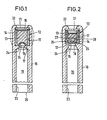
- Fig. 1 einen Längsschnitt durch eine erste Ausführungsform des pyrotechnischen Dübels, und
- Fig. 2 einen Längsschnitt durch eine zweite Ausführungsform mit Zündhütchen.
- Fig. 1 shows a longitudinal section through a first embodiment of the pyrotechnic anchor, and
- Fig. 2 shows a longitudinal section through a second embodiment with primers.
Der in Fig. 1 dargestellte Dübel weist einen zylindrischen Schaft 10 auf, an dessem vorderen Ende der Verformungsraum 11 gebildet ist. Im Verformungsraum 11 befindet sich die Sprengkapsel 12, die aus einer mit einer pyrotechnischen Ladung 13 gefüllten zylindrischen Hülse 14 besteht. Der Hülsenboden 15 ist dünnwandiger ausgebildet als die Umfangswand der Hülse 14 und er bildet eine Eindrückung, d.h. er ist in Richtung auf das Hülseninnere gewölbt. Das dem Hülsenboden 15 abgewandte offene Hülsenende ist mit einer Dämmplatte 16 verschlossen.The dowel shown in FIG. 1 has a
Die Sprengkapsel 12 stützt sich mit ihrem rückwärtigen Ende (mit der Bodenwand 15) an der ringförmigen Stützwand 17 ab, die dem Schaft 10 einstückig angeformt ist und die den Verformungsraum 11 nach hinten begrenzt. Durch eine axiale öffnung 18 in der Stützwand 17 steht der Verformungsraum 11 mit dem Längskanal 19 in Verbindung, der sich bis zum rückwärtigen Ende 20 des Schafts 10 erstreckt und dort frei ausläuft.The
Nach vorne wird der Verformungsraum 11 von einer scheibenförmigen Deckplatte 21 begrenzt, die von der Schaftwand durch Bördelung 22 umgriffen wird.Towards the front, the
Der Längskanal 19 weist ein Innengewinde 23 auf.The
Beim Einsatz des pyrotechnischen Dübels wird in die Wand, in der der Dübel befestigt werden soll, ein Loch gebohrt, das dem Außendurchmesser des Schafts 10 entspricht. Der Dübel wird in dieses Loch eingeschoben. Anschließend wird eine stabförmige Auslösevorrichtung, die am vorderen Ende eine Heizvorrichtung trägt, in den Längskanal 19 eingeführt. Die Heizvorrichtung dringt durch die öffnung 18 bis zum Hülsenboden 15 vor, wobei sie durch die schräge Ringfläche 24 der Stützwand in das Loch 18 geführt wird. Die heiße Spitze der (nicht dargestellten) Auslösevorrichtung bringt durch direkten Kontakt mit dem Hülsenboden 15 die pyrotechnische Ladung 13 zur Auslösung, wobei sich die Wand des Verformungsraums 11 aufweitet, sowie dies in Fig. 1 gestrichelt dargestellt ist. Hierbei erfolgt eine nahezu plastische Anpassung des Metalls des Verformungsraums an das umgebende Material. Durch das pyrotechnische Spreizen des Verformungsraums wird ein guter Halt des Dübels in der Wand erreicht. Dieser Halt kann noch dadurch unterstützt werden, daß der Dübel im Bereich des Innengewindes 23 spreizbar ist und durch Einschrauben eines (nicht dargestellten) Schraubbolzens aufgeweitet wird. Das Ausführungsbeispiel von Fig. 2 entspricht weitgehend demjenigen der Fig. 1, so daß die nachfolgende Beschreibung sich auf die Erläuterung der Unterschiede beschränkt.When using the pyrotechnic dowel, a hole is drilled in the wall in which the dowel is to be fastened, which hole corresponds to the outer diameter of the
Gemäß Fig. 2 enthält die Sprengkapsel 12 außer der pyrotechnischen Ladung 13 ein Zündhütchen 25, mit einer auf dem flachen Hülsenboden 15 angeordneten Initialladung 26, die durch Eindrücken des Hülsenbodens 15 gegen ein Widerlager 27 gedrückt wird. Das Innere des Zündhütchens 25 ist über eine Bohrung 28 mit dem die Ladung 13 enthaltenden Raum verbunden. Bei einem Schlag, der auf den Hülsenboden 15 ausgeübt wird, wird die Initialladung 26 durch Druckwirkung entzündet. Die Initialladung 26 zündet ihrerseits durch die Bohrung 28, die Hauptladung 13 thermisch an.2, the
Beim Einsatz des Dübels nach Fig. 2 wird, nachdem der Dübel in eine entsprechende Bohrung der Wand eingeschoben worden ist, ein Dorn in den Längskanal 19 eingeführt. Nachdem das vordere Ende des Dorns den Hülsenboden 15 erreicht hat, wird mit einem Hammer o.dgl. ein Schlag auf den Dorn ausgeübt, wodurch das Zündhütchen 25 gezündet wird. Dadurch wird die Ladung 13 zur Detonation gebracht und der Verformungsraum 11 aufgeweitet.2, after the dowel has been inserted into a corresponding hole in the wall, a mandrel is inserted into the
Alternativ besteht die Möglichkeit, den Dübel von Fig. 2 mit einem entsprechenden Auslösewerkzeug, das einen Ultraschallkopf aufweist, zu zünden.Alternatively, there is the possibility of igniting the dowel of FIG. 2 with a corresponding release tool that has an ultrasound head.
Die Ladung 13 kann beispielsweise folgende Zusammensetzung enthalten:

Claims (5)
Applications Claiming Priority (2)
| Application Number | Priority Date | Filing Date | Title |
|---|---|---|---|
| DE19863613624 DE3613624A1 (en) | 1986-04-23 | 1986-04-23 | PYROTECHNICAL DOWEL |
| DE3613624 | 1986-04-23 |
Publications (1)
| Publication Number | Publication Date |
|---|---|
| EP0243745A1 true EP0243745A1 (en) | 1987-11-04 |
Family
ID=6299270
Family Applications (1)
| Application Number | Title | Priority Date | Filing Date |
|---|---|---|---|
| EP87105171A Ceased EP0243745A1 (en) | 1986-04-23 | 1987-04-08 | Pyrotechnic dowel |
Country Status (4)
| Country | Link |
|---|---|
| US (1) | US4909686A (en) |
| EP (1) | EP0243745A1 (en) |
| JP (1) | JPS62251510A (en) |
| DE (1) | DE3613624A1 (en) |
Cited By (1)
| Publication number | Priority date | Publication date | Assignee | Title |
|---|---|---|---|---|
| WO2009061872A1 (en) * | 2007-11-09 | 2009-05-14 | Illinois Tool Works Inc. | Powder-actuated mechanical lock concrete anchor |
Families Citing this family (9)
| Publication number | Priority date | Publication date | Assignee | Title |
|---|---|---|---|---|
| US5116175A (en) * | 1991-02-19 | 1992-05-26 | Ari Adini | Explosively deformable anchoring assembly |
| DE4445422A1 (en) * | 1994-12-20 | 1996-06-27 | Fischer Artur Werke Gmbh | Anchor bolts that can be anchored by an explosive charge |
| DE19754792A1 (en) * | 1997-12-10 | 1999-06-17 | Dynamit Nobel Ag | Expanding metal dowel |
| DE19754791A1 (en) * | 1997-12-10 | 1999-06-17 | Dynamit Nobel Ag | Expanding metal dowel with pyrotechnic drive |
| DE10338394A1 (en) * | 2002-10-02 | 2004-04-15 | Dynamit Nobel Ais Gmbh Automotive Ignition Systems | Pyro-mechanical fastening element for non-releasable fixed mechanical connection of two components on a motor vehicle, has a metal casing with a pyrotechnic propelling charge adjacent to an adapter |
| KR100544330B1 (en) * | 2003-02-13 | 2006-01-23 | 국방과학연구소 | Explosive bolt |
| ATE426747T1 (en) * | 2004-01-21 | 2009-04-15 | Delphi Tech Inc | NON-DESTRUCTIVE PRESS CONNECTION ON PYROMECHANICAL FASTENING ELEMENTS |
| GB201813483D0 (en) * | 2018-08-18 | 2018-10-03 | Mckernan Michael | A primer holder device |
| CN110107573A (en) * | 2019-04-19 | 2019-08-09 | 蚌埠市行星工程机械有限公司 | Built-in burst point check bolt |
Citations (6)
| Publication number | Priority date | Publication date | Assignee | Title |
|---|---|---|---|---|
| CH236451A (en) * | 1942-07-23 | 1945-02-15 | Dynamit Nobel Ag | Explosive rivets with impact ignition. |
| US2378118A (en) * | 1944-02-25 | 1945-06-12 | Widrich Anton | Explosive rivet |
| US2429239A (en) * | 1941-09-20 | 1947-10-21 | George D Rogers | Explosive rivet |
| DE1072431B (en) * | 1959-12-31 | Ing Max Schmid Mannheim Dr | Pen for welding onto a base | |
| DE2641588A1 (en) * | 1976-09-16 | 1978-03-23 | Dynamit Nobel Ag | FASTENING ELEMENT |
| EP0156082A1 (en) * | 1983-09-21 | 1985-10-02 | ETS DAVEY BICKFORD SMITH & CIE ET SOCIETE ANONYME D'EXPLOSIFS ET DE PRODUITS CHMIQUES | Method of anchoring for the backs and walls of underground galleries, and devices therefor |
Family Cites Families (6)
| Publication number | Priority date | Publication date | Assignee | Title |
|---|---|---|---|---|
| US1400401A (en) * | 1921-09-08 | 1921-12-13 | Allan Frank | Bolt, rivet, and the like |
| US2492590A (en) * | 1942-01-09 | 1949-12-27 | United Air Lines Inc | Hollow rivet with undercut head |
| US3332311A (en) * | 1966-01-19 | 1967-07-25 | Du Pont | Electrically fired explosive fasteners |
| DE1683288A1 (en) * | 1967-09-05 | 1971-02-11 | Arthur Muenz | Fastening device for door frames |
| US3396623A (en) * | 1967-09-29 | 1968-08-13 | Du Pont | Electrically fired explosive fasteners |
| US4511296A (en) * | 1983-03-16 | 1985-04-16 | Invocas, Inc. | Anchor bolt with mechanical keys deployed by internal pressurization |
-
1986
- 1986-04-23 DE DE19863613624 patent/DE3613624A1/en not_active Withdrawn
-
1987
- 1987-04-08 EP EP87105171A patent/EP0243745A1/en not_active Ceased
- 1987-04-23 JP JP62098783A patent/JPS62251510A/en active Pending
-
1988
- 1988-10-25 US US07/261,886 patent/US4909686A/en not_active Expired - Fee Related
Patent Citations (6)
| Publication number | Priority date | Publication date | Assignee | Title |
|---|---|---|---|---|
| DE1072431B (en) * | 1959-12-31 | Ing Max Schmid Mannheim Dr | Pen for welding onto a base | |
| US2429239A (en) * | 1941-09-20 | 1947-10-21 | George D Rogers | Explosive rivet |
| CH236451A (en) * | 1942-07-23 | 1945-02-15 | Dynamit Nobel Ag | Explosive rivets with impact ignition. |
| US2378118A (en) * | 1944-02-25 | 1945-06-12 | Widrich Anton | Explosive rivet |
| DE2641588A1 (en) * | 1976-09-16 | 1978-03-23 | Dynamit Nobel Ag | FASTENING ELEMENT |
| EP0156082A1 (en) * | 1983-09-21 | 1985-10-02 | ETS DAVEY BICKFORD SMITH & CIE ET SOCIETE ANONYME D'EXPLOSIFS ET DE PRODUITS CHMIQUES | Method of anchoring for the backs and walls of underground galleries, and devices therefor |
Cited By (1)
| Publication number | Priority date | Publication date | Assignee | Title |
|---|---|---|---|---|
| WO2009061872A1 (en) * | 2007-11-09 | 2009-05-14 | Illinois Tool Works Inc. | Powder-actuated mechanical lock concrete anchor |
Also Published As
| Publication number | Publication date |
|---|---|
| JPS62251510A (en) | 1987-11-02 |
| DE3613624A1 (en) | 1987-10-29 |
| US4909686A (en) | 1990-03-20 |
Similar Documents
| Publication | Publication Date | Title |
|---|---|---|
| EP0600388B1 (en) | Tandem warhead having piezo-electric igniters | |
| DE1086594B (en) | Dismantling ignition | |
| EP0718506A1 (en) | Anchor bolt fastened by means of explosive charge | |
| EP0243745A1 (en) | Pyrotechnic dowel | |
| DE2701935A1 (en) | COMPRESSED GAS ACTUATED SWITCHING ELEMENT | |
| DE2824703C2 (en) | Bullet with a punch body | |
| DE2444919C3 (en) | Self-immolative head fuse for twist projectiles | |
| DE450061C (en) | Igniter with device to prevent the flashback of the ignition jet | |
| DE828661C (en) | HE grenade | |
| DE2841040A1 (en) | Explosive device with an explosive charge that can be ignited by a detonator | |
| DE102020110916A1 (en) | Firing pin lighter | |
| DE7717006U1 (en) | IGNITORS, IN PARTICULAR FOR HAND GRENADES | |
| DE19747183C2 (en) | Impact detonator with movable pyrotechnic mass | |
| DE1028468B (en) | Dismantling ignition | |
| DE148970C (en) | ||
| EP0239779B1 (en) | Impact igniter | |
| DE2920135A1 (en) | Fuse, delay charge or detonator igniter - with airtight encapsulated large calibre primer of reduced charge wt. ensuring ignition with simple construction | |
| DE1181095B (en) | Whisker | |
| DE102009052660B4 (en) | Pyrotechnic igniter | |
| DE2301957A1 (en) | DELAY IGNITER FOR ONE FLOOR | |
| DE300158C (en) | ||
| DE2842882A1 (en) | STRIKER ON ONE FLOOR | |
| AT228098B (en) | Impact fuse for projectiles | |
| AT228689B (en) | Device for removing rocks | |
| AT164054B (en) | Detonator with delay effect |
Legal Events
| Date | Code | Title | Description |
|---|---|---|---|
| PUAI | Public reference made under article 153(3) epc to a published international application that has entered the european phase |
Free format text: ORIGINAL CODE: 0009012 |
|
| AK | Designated contracting states |
Kind code of ref document: A1 Designated state(s): AT BE CH DE ES FR GB GR IT LI NL SE |
|
| RAP1 | Party data changed (applicant data changed or rights of an application transferred) |
Owner name: HUELS TROISDORF AKTIENGESELLSCHAFT |
|
| RAP1 | Party data changed (applicant data changed or rights of an application transferred) |
Owner name: DYNAMIT NOBEL AKTIENGESELLSCHAFT |
|
| 17P | Request for examination filed |
Effective date: 19880429 |
|
| 17Q | First examination report despatched |
Effective date: 19890216 |
|
| STAA | Information on the status of an ep patent application or granted ep patent |
Free format text: STATUS: THE APPLICATION HAS BEEN REFUSED |
|
| 18R | Application refused |
Effective date: 19901028 |
|
| RIN1 | Information on inventor provided before grant (corrected) |
Inventor name: BRETFELD, ANTON Inventor name: HOMBURG, AXEL, DR. Inventor name: BENDER, RICHARD, DR. |