EP0243608A1 - Apparatus for making a substantially vertical slot in the soil - Google Patents
Apparatus for making a substantially vertical slot in the soil Download PDFInfo
- Publication number
- EP0243608A1 EP0243608A1 EP87102691A EP87102691A EP0243608A1 EP 0243608 A1 EP0243608 A1 EP 0243608A1 EP 87102691 A EP87102691 A EP 87102691A EP 87102691 A EP87102691 A EP 87102691A EP 0243608 A1 EP0243608 A1 EP 0243608A1
- Authority
- EP
- European Patent Office
- Prior art keywords
- cutting wheels
- drive
- ring gear
- drive ring
- housing
- Prior art date
- Legal status (The legal status is an assumption and is not a legal conclusion. Google has not performed a legal analysis and makes no representation as to the accuracy of the status listed.)
- Granted
Links
- 239000002689 soil Substances 0.000 title 1
- 238000007789 sealing Methods 0.000 claims abstract description 4
- 238000004519 manufacturing process Methods 0.000 claims description 3
- 210000001520 comb Anatomy 0.000 claims 1
- 230000005540 biological transmission Effects 0.000 description 2
- NMFHJNAPXOMSRX-PUPDPRJKSA-N [(1r)-3-(3,4-dimethoxyphenyl)-1-[3-(2-morpholin-4-ylethoxy)phenyl]propyl] (2s)-1-[(2s)-2-(3,4,5-trimethoxyphenyl)butanoyl]piperidine-2-carboxylate Chemical compound C([C@@H](OC(=O)[C@@H]1CCCCN1C(=O)[C@@H](CC)C=1C=C(OC)C(OC)=C(OC)C=1)C=1C=C(OCCN2CCOCC2)C=CC=1)CC1=CC=C(OC)C(OC)=C1 NMFHJNAPXOMSRX-PUPDPRJKSA-N 0.000 description 1
- 238000005538 encapsulation Methods 0.000 description 1
- 210000003608 fece Anatomy 0.000 description 1
- 230000012447 hatching Effects 0.000 description 1
- 238000012423 maintenance Methods 0.000 description 1
- 230000036346 tooth eruption Effects 0.000 description 1
Images

Classifications
-
- E—FIXED CONSTRUCTIONS
- E02—HYDRAULIC ENGINEERING; FOUNDATIONS; SOIL SHIFTING
- E02F—DREDGING; SOIL-SHIFTING
- E02F3/00—Dredgers; Soil-shifting machines
- E02F3/04—Dredgers; Soil-shifting machines mechanically-driven
- E02F3/18—Dredgers; Soil-shifting machines mechanically-driven with digging wheels turning round an axis, e.g. bucket-type wheels
-
- E—FIXED CONSTRUCTIONS
- E02—HYDRAULIC ENGINEERING; FOUNDATIONS; SOIL SHIFTING
- E02D—FOUNDATIONS; EXCAVATIONS; EMBANKMENTS; UNDERGROUND OR UNDERWATER STRUCTURES
- E02D17/00—Excavations; Bordering of excavations; Making embankments
- E02D17/13—Foundation slots or slits; Implements for making these slots or slits
-
- E—FIXED CONSTRUCTIONS
- E02—HYDRAULIC ENGINEERING; FOUNDATIONS; SOIL SHIFTING
- E02F—DREDGING; SOIL-SHIFTING
- E02F3/00—Dredgers; Soil-shifting machines
- E02F3/04—Dredgers; Soil-shifting machines mechanically-driven
- E02F3/18—Dredgers; Soil-shifting machines mechanically-driven with digging wheels turning round an axis, e.g. bucket-type wheels
- E02F3/20—Dredgers; Soil-shifting machines mechanically-driven with digging wheels turning round an axis, e.g. bucket-type wheels with tools that only loosen the material, i.e. mill-type wheels
- E02F3/205—Dredgers; Soil-shifting machines mechanically-driven with digging wheels turning round an axis, e.g. bucket-type wheels with tools that only loosen the material, i.e. mill-type wheels with a pair of digging wheels, e.g. slotting machines
Definitions
- the invention relates generically to a device for introducing an essentially vertical bottom slot in the course of the manufacture of a sealing or support wall, - with machine frame, bearing plate, at least two cutting wheels and motor / gear arrangement, the bearing plate being connected to the machine frame and carries the cutting wheels and the motor / gear arrangement, furthermore the cutting wheels are arranged on a common shaft and parts of the gear arrangement are encompassed by a cutting wheel.
- the end shield can be connected to the machine frame in a steerable manner (DE-OS 36 02 387, PatG ⁇ 3, (2)).
- the drive motors are located above the bearing plate in the machine frame. Transmission elements lead from these drive motors through recesses and cavities in the end shield up to the area of the axis of the cutting wheels. Other gears are also accommodated in recesses or cavities in the end shield.
- the recesses or cavities become larger with increasing drive torque for the cutting wheels. They reduce the moment of inertia of the end shield. So that the considerable stresses can nonetheless be absorbed, the end shield must be made correspondingly thick. This is disadvantageous because it results in a relatively wide distance between the cutting wheels on the end plate side and consequently a disturbingly wide bottom rib remains between the cutting wheels when they are working.
- the invention has for its object to further develop a generic device so that can work with a very narrow bearing plate with a small bearing plate side distance of the cutting wheels and nonetheless large drive torques can be entered into the cutting wheels.
- the invention teaches that a double-sided projecting tubular housing is connected to the bearing plate, in which the two cutting wheels with surrounding hubs, which are placed on the common shaft, are mounted, that on one of the hubs a drive ring gear for the Cutting wheels is placed, which is fitted into the housing with clearance, and that the drive ring gear meshes with the drive pinions of a plurality of drive motors distributed over the circumference of the drive ring gear, which are mounted on a drive motor carrier inserted into the housing.
- a preferred embodiment of the invention which is characterized by simplicity and functional reliability, is characterized in that the cutting wheels are mounted with their hubs in the housing by means of tapered roller bearings.
- the drive ring gear is expediently placed on the assigned hub by means of a clamping set.
- the number of drive motors distributed over the circumference of the drive ring gear is arbitrary. In order to achieve very uniform stress conditions, at least three drive motors will generally be provided.
- a preferred embodiment of the Erfin Dung which allows very large drive torques to be introduced into the cutting wheels, is characterized in that five drive motors are arranged over the circumference of the drive ring gear, which are designed as hydraulic motors.
- the cutting wheels will generally be placed on the common shaft with the interposition of a toothing, the cutting wheels can then also be easily removed during maintenance and care work.
- the device according to the invention can be used with a very narrow bearing plate and consequently with a small distance between the cutting wheels on the bearing plate side. Therefore, only a narrow bottom rib remains between the cutting wheels, which breaks away or can be easily washed away.
- the housing essential for the invention also ensures a safe encapsulation of the motor / gear arrangement. It goes without saying that suitable seals are arranged between the rotating and the non-rotating parts. Gaps between rotating and non-rotating parts can be easily flushed and thus kept free.
- the device shown in detail in the figures serves to introduce an essentially vertical bottom slot in the course of the production of a sealing or support wall.
- the non-rotating parts were drawn in thicker lines for clarity than the rotating parts shown with more hatching. Belong to the basic structure. a machine frame, a bearing plate 1, at least two cutting wheels 2 and a motor / transmission arrangement 3.
- the machine frame was not drawn.
- the bearing plate 1 is connected to the machine frame, optionally steerable. It carries the cutting wheels 2 and the motor / gear arrangement 3.
- the cutting wheels 2 are arranged on a common shaft 4. Parts of the gear arrangement are encompassed by a cutting wheel 2.
- a tubular housing 5 projecting on both sides is connected to the end shield 1 and is largely connected to the cutting wheels 2 by a connection to the tubular part of the housing 5 which cover 6 is completed.
- the two cutting wheels 2 are mounted with surrounding hubs 7 placed on the common shaft 4.
- a drive ring gear 8 for the cutting wheels 2 is placed on the right of the hubs 7, a drive ring gear 8 for the cutting wheels 2 is placed. This is fitted into the housing 5 with circumferential running play S.
- the drive ring gear 8 meshes with the drive pinion 9 of a plurality of drive motors 3, which are distributed over the circumference of the drive ring gear 8.
- These drive motors 3 are mounted on a drive motor carrier 10 inserted into the housing.
- the cutting wheels 2 are supported with their hubs 7 in the housing by means of tapered roller bearings 11.
- the drive ring gear 8 is placed on the associated hub 7 by means of the clamping set 12.
- five drive motors 3 are arranged over the circumference of the drive ring gear 8. These are designed as hydraulic motors.
- the cutting wheels 2 are placed on the common shaft 4 with the interposition of a toothing 13.
- the cutting wheels 2 are provided on the circumference with cutting teeth 14.
Landscapes
- Engineering & Computer Science (AREA)
- Mining & Mineral Resources (AREA)
- Civil Engineering (AREA)
- General Engineering & Computer Science (AREA)
- Structural Engineering (AREA)
- Mechanical Engineering (AREA)
- Life Sciences & Earth Sciences (AREA)
- General Life Sciences & Earth Sciences (AREA)
- Paleontology (AREA)
- Crushing And Pulverization Processes (AREA)
- Pit Excavations, Shoring, Fill Or Stabilisation Of Slopes (AREA)
- Excavating Of Shafts Or Tunnels (AREA)
- Retarders (AREA)
- Hydraulic Motors (AREA)
Abstract
Vorrichtung zum Einbringen eines im wesentlichen vertikalen Bodenschlitzes im Zuge der Herstellung einer Dicht- oder Stützwand, mit Maschinenrahmen, Lagerschild, zumindest zwei Schneidrädern und Motor/Getriebe-Anordnung. Der Lagerschild (1) ist an den Maschinenrahmen angeschlossen und trägt die Schneidräder (2) sowie die Motor/Getriebe-Anordnung (3). Die Schneidräder sind auf einer gemeinsamen Welle (4) angeordnet und Teile der Getriebeanordnung sind von einem Schneidrad umfaßt. An den Lagerschild ist ein beidseits vorkragendes, rohrförmiges Gehäuse angeschlossen, in dem die beiden Schneidräder mit einfassenden Naben (7), die auf die gemeinsame Welle aufgesetzt sind, gelagert sind. Auf eine der Naben ist ein Antriebshohlrad (8) für die Schneidräder aufgesetzt, welches in das Gehäuse mit Umlaufspiel eingepaßt ist. Das Antriebshohlrad kämmt mit den Antriebsritzeln (9) einer Mehrzahl von über den Umfang des Antriebshohlrades verteilten Antriebsmotoren, die an einem in das Gehäuse eingesetzten Antriebsmotorträger (10) gelagert sind. 
Description
Die Erfindung bezieht sich gattungsgemäß auf eine Vorrichtung zum Einbringen eines im wesentlichen vertikalen Bodenschlitzes im Zuge der Herstellung einer Dicht- oder Stützwand, - mit Maschinenrahmen, Lagerschild, zumindest zwei Schneidrädern und Motor/Getriebe-Anordnung, wobei der Lagerschild an den Maschinenrahmen angeschlossen ist und die Schneidräder sowie die Motor/Getriebe-Anordnung trägt, wobei fernerhin die Schneidräder auf einer gemeinsamen Welle angeordnet sind und Teile der Getriebeanordnung von einem Schneidrad umfaßt sind. Es versteht sich, daß der Lagerschild an den Maschinenrahmen lenkbar angeschlossen sein kann (DE-OS 36 02 387, PatG § 3, (2)).The invention relates generically to a device for introducing an essentially vertical bottom slot in the course of the manufacture of a sealing or support wall, - with machine frame, bearing plate, at least two cutting wheels and motor / gear arrangement, the bearing plate being connected to the machine frame and carries the cutting wheels and the motor / gear arrangement, furthermore the cutting wheels are arranged on a common shaft and parts of the gear arrangement are encompassed by a cutting wheel. It goes without saying that the end shield can be connected to the machine frame in a steerable manner (DE-OS 36 02 387, PatG § 3, (2)).
Bei der bekannten gattungsgemäßen Ausführungsform (DE-OS 34 24 999, PatG § 3 (1)) befinden sich die Antriebsmotoren oberhalb des Lagerschildes im Maschinenrahmen. Transmissionselemente führen von diesen Antriebsmotoren durch Ausnehmungen und Auskammerungen des Lagerschildes bis in den Bereich der Achse der Schneidräder. In Ausnehmungen oder Auskammerungen des Lagerschildes sind auch andere Getriebe untergebracht. Die Ausnehmungen oder Auskammerungen werden mit zunehmendem Antriebsdrehmoment für die Schneidräder größer. Sie reduzieren das Flächenträgheitsmoment des Lagerschildes. Damit nichtsdestoweniger die erheblichen Beanspruchungen aufgenommen werden können, muß der Lagerschild entsprechend dick ausgeführt werden. Das ist nachteilig, weil daraus ein verhältnismäßig breiter lagerschildseitiger Abstand der Schneidräder resultiert und folglich bei arbeitenden Schneidrädern zwischen diesen eine störend breite Bodenrippe stehenbleibt.In the known generic embodiment (DE-OS 34 24 999, PatG § 3 (1)), the drive motors are located above the bearing plate in the machine frame. Transmission elements lead from these drive motors through recesses and cavities in the end shield up to the area of the axis of the cutting wheels. Other gears are also accommodated in recesses or cavities in the end shield. The recesses or cavities become larger with increasing drive torque for the cutting wheels. They reduce the moment of inertia of the end shield. So that the considerable stresses can nonetheless be absorbed, the end shield must be made correspondingly thick. This is disadvantageous because it results in a relatively wide distance between the cutting wheels on the end plate side and consequently a disturbingly wide bottom rib remains between the cutting wheels when they are working.
Der Erfindung liegt die Aufgabe zugrunde, eine gattungsgemäße Vorrichtung so weiter auszubilden, daß mit einem sehr schmalen Lagerschild mit geringem lagerschildseitigen Abstand der Schneidräder gearbeitet werden kann und nichtsdestoweniger große Antriebsdrehmomente in die Schneidräder eingetragen werden können.The invention has for its object to further develop a generic device so that can work with a very narrow bearing plate with a small bearing plate side distance of the cutting wheels and nonetheless large drive torques can be entered into the cutting wheels.
Zur Lösung dieser Aufgabe lehrt die Erfindung, daß an den Lagerschild ein beidseits vorkragendes, rohrförmiges Gehäuse angeschlossen ist, in dem die beiden Schneidräder mit einfassenden Naben, die auf die gemeinsame Welle aufgesetzt sind, gelagert sind, daß auf eine der Naben ein Antriebshohlrad für die Schneidräder aufgesetzt ist, welches in das Gehäuse mit Umlaufspiel eingepaßt ist, und daß das Antriebshohlrad mit den Antriebsritzeln einer Mehrzahl von über den Umfang des Antriebshohlrades verteilten Antriebsmotoren kämmt, die an einem in das Gehäuse eingesetzten Antriebsmotorträger gelagert sind.To achieve this object, the invention teaches that a double-sided projecting tubular housing is connected to the bearing plate, in which the two cutting wheels with surrounding hubs, which are placed on the common shaft, are mounted, that on one of the hubs a drive ring gear for the Cutting wheels is placed, which is fitted into the housing with clearance, and that the drive ring gear meshes with the drive pinions of a plurality of drive motors distributed over the circumference of the drive ring gear, which are mounted on a drive motor carrier inserted into the housing.
Das läßt sich im einzelnen auf verschiedene Weise verwirklichen. Eine bevorzugte Ausführungsform der Erfindung, die sich durch Einfachheit und Funktionssicherheit auszeichnet, ist dadurch gekennzeichnet, daß die Schneidräder mit ihren Naben in dem Gehäuse mittels Kegelrollenlager gelagert sind. Das Antriebshohlrad ist zweckmäßigerweise auf die zugeordnete Nabe mittels Spannsatz aufgesetzt. Die Anzahl der über den Umfang des Antriebshohlrades verteilten Antriebsmotoren ist grundsätzlich beliebig. Zur Erzielung sehr gleichmäßiger Beanspruchungsverhältnisse wird man im allgemeinen zumindest drei Antriebsmotoren vorsehen. Eine bevorzugte Ausführungsform der Erfin dung, die es erlaubt, sehr große Antriebsdrehmomente in die Schneidräder einzuleiten, ist dadurch gekennzeichnet, daß über den Umfang des Antriebshohlrades fünf Antriebsmotoren angeordnet sind, die als Hydraulikmotoren ausgeführt sind. Die Schneidräder wird man auf die gemeinsame Welle im allgemeinen unter Zwischenschaltung einer Verzahnung aufsetzen, die Schneidräder können dann bei Wartungs- und Pflegearbeiten auch leicht abgezogen werden.This can be achieved in various ways. A preferred embodiment of the invention, which is characterized by simplicity and functional reliability, is characterized in that the cutting wheels are mounted with their hubs in the housing by means of tapered roller bearings. The drive ring gear is expediently placed on the assigned hub by means of a clamping set. In principle, the number of drive motors distributed over the circumference of the drive ring gear is arbitrary. In order to achieve very uniform stress conditions, at least three drive motors will generally be provided. A preferred embodiment of the Erfin Dung, which allows very large drive torques to be introduced into the cutting wheels, is characterized in that five drive motors are arranged over the circumference of the drive ring gear, which are designed as hydraulic motors. The cutting wheels will generally be placed on the common shaft with the interposition of a toothing, the cutting wheels can then also be easily removed during maintenance and care work.
Die erreichten Vorteile sind darin zu sehen, daß bei der erfindungsgemäßen Vorrichtung mit einem sehr schmalen Lagerschild und folglich mit einem geringen lagerschildseitigen Abstand der Schneidräder gearbeitet werden kann. Zwischen den Schneidrädern bleibt daher nur eine schmale Bodenrippe stehen, die wegbricht oder leicht freigespült werden kann. Das für die Erfindung wesentliche Gehäuse bewirkt zugleich eine sichere Kapselung der Motor/Getriebe-Anordnung. Es versteht sich, daß zwischen den rotierenden und den nichtrotierenden Teilen geeignete Dichtungen angeordnet werden. Spalträume zwischen rotierenden und nichtrotierenden Teilen können ohne Schwierigkeiten gespült und dadurch freigehalten werden.The advantages achieved can be seen in the fact that the device according to the invention can be used with a very narrow bearing plate and consequently with a small distance between the cutting wheels on the bearing plate side. Therefore, only a narrow bottom rib remains between the cutting wheels, which breaks away or can be easily washed away. The housing essential for the invention also ensures a safe encapsulation of the motor / gear arrangement. It goes without saying that suitable seals are arranged between the rotating and the non-rotating parts. Gaps between rotating and non-rotating parts can be easily flushed and thus kept free.
Im folgenden wird die Erfindung anhand einer lediglich ein Ausführungsbeispiel darstellenden Zeichnung ausführlicher erläutert. Es zeigen in schematischer Darstellung
- Fig. 1 einen Vertikalschnitt durch eine erfindungsgemäße Vorrichtung ausschnittsweise und
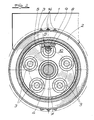
- Fig. 2 einen Schnitt in Richtung A-A durch den Gegenstand nach Fig. 1, ebenfalls ausschnittsweise.
- Fig. 1 shows a vertical section through a device according to the invention in sections and
- Fig. 2 shows a section in the direction AA through the object of FIG. 1, also in part.
Die in den Figuren ausschnittsweise dargestellte Vorrichtung dient zum Einbringen eines im wesentlichen vertikalen Bodenschlitzes im Zuge der Herstellung einer Dicht- oder Stützwand. Die nichtrotierenden Teile wurden zur Verdeutlichung in dickerer Strichführung gezeichnet als die mit engerer Schraffierung dargestellten rotierenden Teile. Zum grundsätzlichen Aufbau gehören.
ein Maschinenrahmen,
ein Lagerschild 1,
zumindest zwei Schneidräder 2 und
eine Motor/Getriebe-Anordnung 3.The device shown in detail in the figures serves to introduce an essentially vertical bottom slot in the course of the production of a sealing or support wall. The non-rotating parts were drawn in thicker lines for clarity than the rotating parts shown with more hatching. Belong to the basic structure.
a machine frame,
a bearing plate 1,
at least two
a motor /
Der Maschinenrahmen wurde nicht gezeichnet. Der Lagerschild 1 ist, gegebenenfalls lenkbar, an den Maschinenrahmen angeschlossen. Er trägt die Schneidräder 2 sowie die Motor/Getriebe-Anordnung 3. Die Schneidräder 2 sind auf einer gemeinsamen Welle 4 angeordnet. Teile der Getriebeanordnung sind von einem Schneidrad 2 umfaßt.The machine frame was not drawn. The bearing plate 1 is connected to the machine frame, optionally steerable. It carries the
An den Lagerschild 1 ist ein beidseits vorkragendes rohrförmiges Gehäuse 5 angeschlossen, welches zu den Schneidrädern 2 hin weitgehend durch einen mit dem rohrförmigen Teil des Gehäuses 5 verbun denen Deckel 6 abgeschlossen ist. In dem Gehäuse 5, genauer in dem Deckel 6, sind die beiden Schneidräder 2 mit einfassenden, auf die gemeinsame Welle 4 aufgesetzten Naben 7 gelagert. Auf die rechte der Naben 7 ist ein Antriebshohlrad 8 für die Schneidräder 2 aufgesetzt. Dieses ist in das Gehäuse 5 mit Umfangslaufspiel S eingepaßt. Das Antriebshohlrad 8 kämmt mit dem Antriebsritzel 9 einer Mehrzahl von Antriebsmotoren 3, die über den Umfang des Antriebshohlrades 8 verteilt sind. Diese Antriebsmotoren 3 sind an einem in das Gehäuse eingesetzten Antriebsmotorträger 10 gelagert.A
Die Schneidräder 2 sind mit ihren Naben 7 in dem Gehäuse mittels Kegelrollenlager 11 gelagert. Das Antriebshohlrad 8 ist auf die zugeordnete Nabe 7 mittels Spannsatz 12 aufgesetzt. Im Ausführungsbeispiel sind über den Umfang des Antriebshohlrades 8 fünf Antriebsmotoren 3 angeordnet. Diese sind als Hydraulikmotoren ausgeführt. Die Schneidräder 2 sind auf die gemeinsame Welle 4 unter Zwischenschaltung einer Verzahnung 13 aufgesetzt. Die Schneidräder 2 sind umfangsseitig mit Schneidzähnen 14 versehen.The
Claims (5)
Maschinenrahmen,
Lagerschild,
zumindest zwei Schneidrädern und
Motor/Getriebe-Anordnung,
wobei der Lagerschild an den Maschinenrahmen angeschlossen ist und die Schneidräder sowie die Motor-Getriebe-Anordnung trägt, wobei fernerhin die Schneidräder auf einer gemeinsamen Welle angeordnet sind und Teile der Getriebeanordnung von einem Schneidrad umfaßt sind, dadurch gekennzeichnet, daß an den Lagerschild (1) ein beidseits vorkragendes, rohrförmiges Gehäuse (5) angeschlossen ist,
in dem die beiden Schneidräder (2) mit einfassenden Naben (7), die auf die gemeinsame Welle (4) aufgesetzt sind, gelagert sind,
daß auf eine der Naben (7) ein Antriebshohlrad (8) für die Schneidräder (2) aufgesetzt ist, welches in das Gehäuse (5) mit Umlaufspiel (S) eingepaßt ist, und daß das Antriebshohlrad (8) mit den Abtriebsritzeln (9) einer Mehrzahl von über den Umfang des Antriebshohlrades (8) verteilten Antriebsmotoren (3) kämmt, die an einem in das Gehäuse (5) eingesetzten Antriebsmotorträger (10) gelagert sind.1. Device for introducing a substantially vertical bottom slot in the course of the manufacture of a sealing or retaining wall, with
Machine frame,
End shield,
at least two cutting wheels and
Motor / gearbox arrangement,
the bearing plate being connected to the machine frame and carrying the cutting wheels and the motor-gear arrangement, the cutting wheels also being arranged on a common shaft and parts of the gear arrangement being encompassed by a cutting wheel, characterized in that on the bearing plate (1) a tubular housing (5) projecting on both sides is connected,
in which the two cutting wheels (2) are mounted with surrounding hubs (7) which are placed on the common shaft (4),
that on one of the hubs (7) a drive ring gear (8) for the cutting wheels (2) is fitted, which is fitted into the housing (5) with clearance (S), and that the drive ring gear (8) with the driven pinions (9) combs a plurality of drive motors (3) distributed over the circumference of the drive ring gear (8), which are mounted on a drive motor support (10) inserted into the housing (5).
Applications Claiming Priority (2)
| Application Number | Priority Date | Filing Date | Title |
|---|---|---|---|
| DE19863612020 DE3612020A1 (en) | 1986-04-10 | 1986-04-10 | DEVICE FOR INSERTING AN ESSENTIAL VERTICAL FLOOR SLOT |
| DE3612020 | 1986-04-10 |
Publications (2)
| Publication Number | Publication Date |
|---|---|
| EP0243608A1 true EP0243608A1 (en) | 1987-11-04 |
| EP0243608B1 EP0243608B1 (en) | 1989-06-14 |
Family
ID=6298357
Family Applications (1)
| Application Number | Title | Priority Date | Filing Date |
|---|---|---|---|
| EP87102691A Expired EP0243608B1 (en) | 1986-04-10 | 1987-02-25 | Apparatus for making a substantially vertical slot in the soil |
Country Status (5)
| Country | Link |
|---|---|
| US (1) | US4785559A (en) |
| EP (1) | EP0243608B1 (en) |
| JP (1) | JPH0711148B2 (en) |
| CS (1) | CS262688B2 (en) |
| DE (1) | DE3612020A1 (en) |
Cited By (1)
| Publication number | Priority date | Publication date | Assignee | Title |
|---|---|---|---|---|
| WO2021052976A3 (en) * | 2019-09-20 | 2021-06-03 | Liebherr-Components Biberach Gmbh | Trench cutter drive with decoupled inner wheel/integrated bearing |
Families Citing this family (23)
| Publication number | Priority date | Publication date | Assignee | Title |
|---|---|---|---|---|
| FR2604460B1 (en) * | 1986-09-26 | 1991-05-10 | Soletanche | DEVICE FOR A MACHINE FOR EXCAVATING TRENCHES IN THE SOIL BY MILLING |
| DE3819525C1 (en) * | 1988-06-08 | 1989-12-28 | Hochtief Ag Vorm. Gebr. Helfmann, 4300 Essen, De | Apparatus for making an essentially vertical soil trench |
| US5003733A (en) * | 1989-07-26 | 1991-04-02 | Strobl Jr Frederick P | Structure and components for enclosing sun spaces and the like and method for erecting same |
| DE3926976C2 (en) * | 1989-08-16 | 1995-02-02 | Hochtief Ag Hoch Tiefbauten | Device for introducing a substantially vertical bottom slot |
| US5212892A (en) * | 1992-10-15 | 1993-05-25 | Maitlen C Gene | Cutter head assembly for excavating machine |
| AR004288A1 (en) * | 1995-11-13 | 1998-11-04 | Siemens Ag | OPTICAL FIBER CABLE INSTALLATION STRUCTURE. |
| US7351009B2 (en) * | 1998-05-06 | 2008-04-01 | Corning Cable Systems Llc | Fiber optic installation structures in a paved surface, ducts, and methods therefor |
| AUPP764598A0 (en) * | 1998-12-11 | 1999-01-14 | R N Cribb Pty Limited | Rotary drum cutting head |
| EP1291490A3 (en) * | 2001-09-06 | 2003-05-21 | Bechem, Hannelore | Excavating tool for rock, minerals etc |
| ITBO20010632A1 (en) * | 2001-10-16 | 2003-04-16 | Simex Engineering S R L | HYDRAULIC MILLING MACHINE FOR EXCAVATOR MACHINES |
| DE20205832U1 (en) * | 2002-04-15 | 2002-08-08 | Sandholzer, Hartwig, 87474 Buchenberg | Holding handle for rotating tillage elements |
| US6837654B2 (en) | 2002-12-12 | 2005-01-04 | Corning Cable Systems Llc | Fiber optic cable secured in a groove |
| JP4505212B2 (en) * | 2003-01-10 | 2010-07-21 | 美津濃株式会社 | Shoes and double raschel warp knitted fabric used therefor |
| DE10308538C5 (en) | 2003-02-27 | 2014-11-06 | Bauer Maschinen Gmbh | Method of making a trench wall in the ground, trench wall cutter and trench wall cutter |
| DE10308539B3 (en) * | 2003-02-27 | 2004-06-03 | Bauer Maschinen Gmbh | Cutting device for cutting grooves in the ground comprises cutting elements arranged on the cutting wheels to remove soil using a rotary action |
| US20040234215A1 (en) * | 2003-05-23 | 2004-11-25 | Serrano Jorge R. | Exterior installation of armored fiber optic cable |
| DE502004007221D1 (en) * | 2004-03-26 | 2008-07-03 | Bauer Maschinen Gmbh | Trench cutter |
| JP4951511B2 (en) * | 2004-07-19 | 2012-06-13 | シミジョー・プロプライエタリー・リミテッド | Cutting machine and method for removing rock or hard soil using this cutting machine |
| DE502004005279D1 (en) * | 2004-08-23 | 2007-11-29 | Bauer Maschinen Gmbh | Apparatus and method for creating a diaphragm wall in the ground |
| FR2899608B1 (en) * | 2006-04-06 | 2010-04-16 | Cie Du Sol | DRILLING TOOLS |
| FR2904339B1 (en) * | 2006-07-28 | 2011-03-04 | Cie Du Sol | CUTTING HEAD FOR AN EXCAVATION MACHINE |
| FR2904338B1 (en) * | 2006-07-28 | 2011-03-04 | Cie Du Sol | CUTTING HEAD FOR EXCAVATION MACHINE |
| IT1400429B1 (en) * | 2009-12-15 | 2013-05-31 | Soilmec Spa | TOOL FOR THIN DIAPHRAGMENTS. |
Citations (4)
| Publication number | Priority date | Publication date | Assignee | Title |
|---|---|---|---|---|
| DE2362425A1 (en) * | 1972-12-14 | 1975-01-30 | Hydrosol | DEVICE FOR MAKING HOLES IN THE SOIL |
| FR2316487A1 (en) * | 1975-06-30 | 1977-01-28 | Jouot Pierre | Independent wheel drive for tractors - uses flexible tyred wheel to drive inside surface of drum fixed to road wheel |
| FR2499607A1 (en) * | 1981-02-06 | 1982-08-13 | Gautier Andre | Vehicle for digging trenches - includes pneumatic driving wheels which bear onto internal surface of main cutter wheel |
| GB2123362A (en) * | 1982-04-08 | 1984-02-01 | Wheelpower Limited | A self-propelling hub unit |
Family Cites Families (9)
| Publication number | Priority date | Publication date | Assignee | Title |
|---|---|---|---|---|
| CA524667A (en) * | 1956-05-01 | The United Electric Coal Companies | Supporting structure for excavating wheel | |
| US3933053A (en) * | 1973-03-20 | 1976-01-20 | Banister Pipelines Ltd. | Ditcher |
| ZA761633B (en) * | 1975-07-17 | 1977-03-30 | Unit Rig & Equip | Two wheel excavating and loading system |
| ZA761636B (en) * | 1975-07-17 | 1977-04-27 | Unit Rig & Equip | All electric excavating and loading system |
| NL170763C (en) * | 1978-07-31 | 1982-12-16 | Nederlandse Offshore Co | Apparatus for digging a trench under a pipeline laid on the water bottom, which apparatus is provided with two excavator wheels placed next to each other on the opposite side of the pipeline, which encloses a sharp corner. |
| DD145294A1 (en) * | 1979-08-08 | 1980-12-03 | Rolf Rueger | PADDLE |
| US4662684A (en) * | 1979-12-13 | 1987-05-05 | H. B. Zachery Corporation | Rotary rock and trench cutting saw |
| DE3424999C2 (en) * | 1984-07-06 | 1994-01-13 | Bauer Spezialtiefbau | Trench cutter |
| DE3602387C1 (en) * | 1986-01-28 | 1987-06-04 | Hochtief Ag Hoch Tiefbauten | Device for introducing a substantially vertical bottom slot |
-
1986
- 1986-04-10 DE DE19863612020 patent/DE3612020A1/en active Granted
-
1987
- 1987-02-25 EP EP87102691A patent/EP0243608B1/en not_active Expired
- 1987-03-30 JP JP62074592A patent/JPH0711148B2/en not_active Expired - Lifetime
- 1987-03-30 US US07/032,334 patent/US4785559A/en not_active Expired - Fee Related
- 1987-04-08 CS CS872534A patent/CS262688B2/en unknown
Patent Citations (4)
| Publication number | Priority date | Publication date | Assignee | Title |
|---|---|---|---|---|
| DE2362425A1 (en) * | 1972-12-14 | 1975-01-30 | Hydrosol | DEVICE FOR MAKING HOLES IN THE SOIL |
| FR2316487A1 (en) * | 1975-06-30 | 1977-01-28 | Jouot Pierre | Independent wheel drive for tractors - uses flexible tyred wheel to drive inside surface of drum fixed to road wheel |
| FR2499607A1 (en) * | 1981-02-06 | 1982-08-13 | Gautier Andre | Vehicle for digging trenches - includes pneumatic driving wheels which bear onto internal surface of main cutter wheel |
| GB2123362A (en) * | 1982-04-08 | 1984-02-01 | Wheelpower Limited | A self-propelling hub unit |
Cited By (1)
| Publication number | Priority date | Publication date | Assignee | Title |
|---|---|---|---|---|
| WO2021052976A3 (en) * | 2019-09-20 | 2021-06-03 | Liebherr-Components Biberach Gmbh | Trench cutter drive with decoupled inner wheel/integrated bearing |
Also Published As
| Publication number | Publication date |
|---|---|
| JPH0711148B2 (en) | 1995-02-08 |
| US4785559A (en) | 1988-11-22 |
| DE3612020A1 (en) | 1987-10-15 |
| EP0243608B1 (en) | 1989-06-14 |
| DE3612020C2 (en) | 1989-09-14 |
| CS253487A2 (en) | 1988-08-16 |
| CS262688B2 (en) | 1989-03-14 |
| JPS62242094A (en) | 1987-10-22 |
Similar Documents
| Publication | Publication Date | Title |
|---|---|---|
| EP0243608B1 (en) | Apparatus for making a substantially vertical slot in the soil | |
| EP0138807B1 (en) | Driving mechanism | |
| EP0109652A2 (en) | Centrifuge | |
| DE2639591B2 (en) | ||
| DE7037323U (en) | Transmission for an agricultural machine | |
| DE2926261B2 (en) | Device for cleaning the revolving cover of a card | |
| DE2301550A1 (en) | POWER TRANSMISSION DEVICE FOR MOTOR VEHICLES | |
| DE2211280B1 (en) | THREADING TOOL FOR A MINING NICHE DRIVING OR EXTRACTION MACHINE | |
| DE2206667A1 (en) | Drive device, in particular for driving the drive or the crawler tracks of heavy vehicles, such as bulldozers, cranes, shovel excavators or the like | |
| DE932720C (en) | Drive device for circular scratches in settling containers | |
| DE1148054B (en) | Hoist winch for elevators | |
| DE3926976C2 (en) | Device for introducing a substantially vertical bottom slot | |
| DE681826C (en) | Device for moving the brushes of commutator motors | |
| DE438528C (en) | Pulley with electric drive | |
| DE3017660C2 (en) | ||
| DE2926812C2 (en) | Method and device for changing the direction of travel of card flats | |
| DE3819525C1 (en) | Apparatus for making an essentially vertical soil trench | |
| DE2716069C3 (en) | Drive device for the agitator of a sewage treatment plant | |
| DE1557104B2 (en) | Agitator drive | |
| DE2738123A1 (en) | MIXING MACHINE | |
| DE2155666A1 (en) | ||
| DE2107793A1 (en) | Gear for driving a road roller | |
| DE506536C (en) | Coal cutting machine | |
| EP0065928A2 (en) | Method for driving a type disk in a disk printer and disk printer therefore | |
| DE2064830A1 (en) | Motor-gear unit |
Legal Events
| Date | Code | Title | Description |
|---|---|---|---|
| PUAI | Public reference made under article 153(3) epc to a published international application that has entered the european phase |
Free format text: ORIGINAL CODE: 0009012 |
|
| 17P | Request for examination filed |
Effective date: 19870325 |
|
| AK | Designated contracting states |
Kind code of ref document: A1 Designated state(s): BE FR NL |
|
| 17Q | First examination report despatched |
Effective date: 19881124 |
|
| GRAA | (expected) grant |
Free format text: ORIGINAL CODE: 0009210 |
|
| AK | Designated contracting states |
Kind code of ref document: B1 Designated state(s): BE FR NL |
|
| ET | Fr: translation filed | ||
| PLBE | No opposition filed within time limit |
Free format text: ORIGINAL CODE: 0009261 |
|
| STAA | Information on the status of an ep patent application or granted ep patent |
Free format text: STATUS: NO OPPOSITION FILED WITHIN TIME LIMIT |
|
| 26N | No opposition filed | ||
| PGFP | Annual fee paid to national office [announced via postgrant information from national office to epo] |
Ref country code: BE Payment date: 19941220 Year of fee payment: 9 |
|
| PGFP | Annual fee paid to national office [announced via postgrant information from national office to epo] |
Ref country code: FR Payment date: 19941228 Year of fee payment: 9 |
|
| PGFP | Annual fee paid to national office [announced via postgrant information from national office to epo] |
Ref country code: NL Payment date: 19950228 Year of fee payment: 9 |
|
| PG25 | Lapsed in a contracting state [announced via postgrant information from national office to epo] |
Ref country code: BE Effective date: 19960228 |
|
| BERE | Be: lapsed |
Owner name: HOCHTIEF A.G. VORM. GEBR. HELFMANN Effective date: 19960228 |
|
| PG25 | Lapsed in a contracting state [announced via postgrant information from national office to epo] |
Ref country code: NL Effective date: 19960901 |
|
| PG25 | Lapsed in a contracting state [announced via postgrant information from national office to epo] |
Ref country code: FR Effective date: 19961031 |
|
| NLV4 | Nl: lapsed or anulled due to non-payment of the annual fee |
Effective date: 19960901 |
|
| REG | Reference to a national code |
Ref country code: FR Ref legal event code: ST |