EP0243547A1 - Vorrichtung zur peritonealen Dialyse im ständigen Strom - Google Patents
Vorrichtung zur peritonealen Dialyse im ständigen Strom Download PDFInfo
- Publication number
- EP0243547A1 EP0243547A1 EP86303335A EP86303335A EP0243547A1 EP 0243547 A1 EP0243547 A1 EP 0243547A1 EP 86303335 A EP86303335 A EP 86303335A EP 86303335 A EP86303335 A EP 86303335A EP 0243547 A1 EP0243547 A1 EP 0243547A1
- Authority
- EP
- European Patent Office
- Prior art keywords
- outflow
- inflow
- dialysis fluid
- fluid
- valve
- Prior art date
- Legal status (The legal status is an assumption and is not a legal conclusion. Google has not performed a legal analysis and makes no representation as to the accuracy of the status listed.)
- Granted
Links
- 238000000502 dialysis Methods 0.000 title claims abstract description 58
- 239000000385 dialysis solution Substances 0.000 claims abstract description 93
- 210000003200 peritoneal cavity Anatomy 0.000 claims abstract description 81
- 239000012530 fluid Substances 0.000 claims abstract description 76
- 238000000034 method Methods 0.000 claims abstract description 41
- 238000012544 monitoring process Methods 0.000 claims description 21
- 125000004122 cyclic group Chemical group 0.000 claims description 7
- 238000002513 implantation Methods 0.000 claims description 2
- 210000004379 membrane Anatomy 0.000 abstract description 20
- 239000012528 membrane Substances 0.000 abstract description 20
- 230000005484 gravity Effects 0.000 abstract description 4
- 230000007423 decrease Effects 0.000 abstract description 2
- 210000003567 ascitic fluid Anatomy 0.000 description 7
- 230000001276 controlling effect Effects 0.000 description 7
- XLYOFNOQVPJJNP-UHFFFAOYSA-N water Substances O XLYOFNOQVPJJNP-UHFFFAOYSA-N 0.000 description 7
- 238000003860 storage Methods 0.000 description 6
- 239000003053 toxin Substances 0.000 description 6
- 230000001580 bacterial effect Effects 0.000 description 5
- 206010000060 Abdominal distension Diseases 0.000 description 4
- 210000001015 abdomen Anatomy 0.000 description 4
- 230000003187 abdominal effect Effects 0.000 description 4
- 238000001631 haemodialysis Methods 0.000 description 4
- 230000000322 hemodialysis Effects 0.000 description 4
- OKTJSMMVPCPJKN-UHFFFAOYSA-N Carbon Chemical compound [C] OKTJSMMVPCPJKN-UHFFFAOYSA-N 0.000 description 3
- 239000008280 blood Substances 0.000 description 3
- 210000004369 blood Anatomy 0.000 description 3
- 229910052799 carbon Inorganic materials 0.000 description 3
- 230000003247 decreasing effect Effects 0.000 description 3
- 238000004519 manufacturing process Methods 0.000 description 3
- 239000002207 metabolite Substances 0.000 description 3
- 239000002245 particle Substances 0.000 description 3
- 239000013618 particulate matter Substances 0.000 description 3
- 238000005086 pumping Methods 0.000 description 3
- 239000000243 solution Substances 0.000 description 3
- 239000012141 concentrate Substances 0.000 description 2
- 238000001802 infusion Methods 0.000 description 2
- 230000007935 neutral effect Effects 0.000 description 2
- 239000003330 peritoneal dialysis fluid Substances 0.000 description 2
- 206010034674 peritonitis Diseases 0.000 description 2
- 230000001105 regulatory effect Effects 0.000 description 2
- 238000001223 reverse osmosis Methods 0.000 description 2
- 230000001954 sterilising effect Effects 0.000 description 2
- 231100000765 toxin Toxicity 0.000 description 2
- 108700012359 toxins Proteins 0.000 description 2
- 241000894006 Bacteria Species 0.000 description 1
- ZAMOUSCENKQFHK-UHFFFAOYSA-N Chlorine atom Chemical compound [Cl] ZAMOUSCENKQFHK-UHFFFAOYSA-N 0.000 description 1
- WQZGKKKJIJFFOK-GASJEMHNSA-N Glucose Natural products OC[C@H]1OC(O)[C@H](O)[C@@H](O)[C@@H]1O WQZGKKKJIJFFOK-GASJEMHNSA-N 0.000 description 1
- 210000000683 abdominal cavity Anatomy 0.000 description 1
- 239000000823 artificial membrane Substances 0.000 description 1
- 238000010923 batch production Methods 0.000 description 1
- 210000004204 blood vessel Anatomy 0.000 description 1
- 229910052801 chlorine Inorganic materials 0.000 description 1
- 239000000460 chlorine Substances 0.000 description 1
- 238000004140 cleaning Methods 0.000 description 1
- 238000011109 contamination Methods 0.000 description 1
- 230000000694 effects Effects 0.000 description 1
- 239000003792 electrolyte Substances 0.000 description 1
- 239000008103 glucose Substances 0.000 description 1
- 239000007943 implant Substances 0.000 description 1
- 210000000936 intestine Anatomy 0.000 description 1
- 210000003734 kidney Anatomy 0.000 description 1
- 230000007257 malfunction Effects 0.000 description 1
- 239000008213 purified water Substances 0.000 description 1
- 150000003839 salts Chemical class 0.000 description 1
- 238000004659 sterilization and disinfection Methods 0.000 description 1
- 239000008399 tap water Substances 0.000 description 1
- 235000020679 tap water Nutrition 0.000 description 1
- 231100000331 toxic Toxicity 0.000 description 1
- 230000002588 toxic effect Effects 0.000 description 1
- 230000001960 triggered effect Effects 0.000 description 1
- 238000011144 upstream manufacturing Methods 0.000 description 1
- 239000002699 waste material Substances 0.000 description 1
Images


Classifications
-
- A—HUMAN NECESSITIES
- A61—MEDICAL OR VETERINARY SCIENCE; HYGIENE
- A61M—DEVICES FOR INTRODUCING MEDIA INTO, OR ONTO, THE BODY; DEVICES FOR TRANSDUCING BODY MEDIA OR FOR TAKING MEDIA FROM THE BODY; DEVICES FOR PRODUCING OR ENDING SLEEP OR STUPOR
- A61M1/00—Suction or pumping devices for medical purposes; Devices for carrying-off, for treatment of, or for carrying-over, body-liquids; Drainage systems
- A61M1/14—Dialysis systems; Artificial kidneys; Blood oxygenators ; Reciprocating systems for treatment of body fluids, e.g. single needle systems for hemofiltration or pheresis
- A61M1/28—Peritoneal dialysis ; Other peritoneal treatment, e.g. oxygenation
-
- A—HUMAN NECESSITIES
- A61—MEDICAL OR VETERINARY SCIENCE; HYGIENE
- A61M—DEVICES FOR INTRODUCING MEDIA INTO, OR ONTO, THE BODY; DEVICES FOR TRANSDUCING BODY MEDIA OR FOR TAKING MEDIA FROM THE BODY; DEVICES FOR PRODUCING OR ENDING SLEEP OR STUPOR
- A61M1/00—Suction or pumping devices for medical purposes; Devices for carrying-off, for treatment of, or for carrying-over, body-liquids; Drainage systems
- A61M1/14—Dialysis systems; Artificial kidneys; Blood oxygenators ; Reciprocating systems for treatment of body fluids, e.g. single needle systems for hemofiltration or pheresis
- A61M1/16—Dialysis systems; Artificial kidneys; Blood oxygenators ; Reciprocating systems for treatment of body fluids, e.g. single needle systems for hemofiltration or pheresis with membranes
- A61M1/1654—Dialysates therefor
- A61M1/1656—Apparatus for preparing dialysates
- A61M1/1668—Details of containers
- A61M1/167—Flexible packaging for solid concentrates
-
- A—HUMAN NECESSITIES
- A61—MEDICAL OR VETERINARY SCIENCE; HYGIENE
- A61M—DEVICES FOR INTRODUCING MEDIA INTO, OR ONTO, THE BODY; DEVICES FOR TRANSDUCING BODY MEDIA OR FOR TAKING MEDIA FROM THE BODY; DEVICES FOR PRODUCING OR ENDING SLEEP OR STUPOR
- A61M1/00—Suction or pumping devices for medical purposes; Devices for carrying-off, for treatment of, or for carrying-over, body-liquids; Drainage systems
- A61M1/14—Dialysis systems; Artificial kidneys; Blood oxygenators ; Reciprocating systems for treatment of body fluids, e.g. single needle systems for hemofiltration or pheresis
- A61M1/16—Dialysis systems; Artificial kidneys; Blood oxygenators ; Reciprocating systems for treatment of body fluids, e.g. single needle systems for hemofiltration or pheresis with membranes
- A61M1/168—Sterilisation or cleaning before or after use
- A61M1/1686—Sterilisation or cleaning before or after use by heat
-
- A—HUMAN NECESSITIES
- A61—MEDICAL OR VETERINARY SCIENCE; HYGIENE
- A61M—DEVICES FOR INTRODUCING MEDIA INTO, OR ONTO, THE BODY; DEVICES FOR TRANSDUCING BODY MEDIA OR FOR TAKING MEDIA FROM THE BODY; DEVICES FOR PRODUCING OR ENDING SLEEP OR STUPOR
- A61M1/00—Suction or pumping devices for medical purposes; Devices for carrying-off, for treatment of, or for carrying-over, body-liquids; Drainage systems
- A61M1/14—Dialysis systems; Artificial kidneys; Blood oxygenators ; Reciprocating systems for treatment of body fluids, e.g. single needle systems for hemofiltration or pheresis
- A61M1/28—Peritoneal dialysis ; Other peritoneal treatment, e.g. oxygenation
- A61M1/282—Operational modes
- A61M1/284—Continuous flow peritoneal dialysis [CFPD]
-
- A—HUMAN NECESSITIES
- A61—MEDICAL OR VETERINARY SCIENCE; HYGIENE
- A61M—DEVICES FOR INTRODUCING MEDIA INTO, OR ONTO, THE BODY; DEVICES FOR TRANSDUCING BODY MEDIA OR FOR TAKING MEDIA FROM THE BODY; DEVICES FOR PRODUCING OR ENDING SLEEP OR STUPOR
- A61M1/00—Suction or pumping devices for medical purposes; Devices for carrying-off, for treatment of, or for carrying-over, body-liquids; Drainage systems
- A61M1/14—Dialysis systems; Artificial kidneys; Blood oxygenators ; Reciprocating systems for treatment of body fluids, e.g. single needle systems for hemofiltration or pheresis
- A61M1/28—Peritoneal dialysis ; Other peritoneal treatment, e.g. oxygenation
- A61M1/285—Catheters therefor
-
- A—HUMAN NECESSITIES
- A61—MEDICAL OR VETERINARY SCIENCE; HYGIENE
- A61M—DEVICES FOR INTRODUCING MEDIA INTO, OR ONTO, THE BODY; DEVICES FOR TRANSDUCING BODY MEDIA OR FOR TAKING MEDIA FROM THE BODY; DEVICES FOR PRODUCING OR ENDING SLEEP OR STUPOR
- A61M1/00—Suction or pumping devices for medical purposes; Devices for carrying-off, for treatment of, or for carrying-over, body-liquids; Drainage systems
- A61M1/71—Suction drainage systems
- A61M1/74—Suction control
-
- A—HUMAN NECESSITIES
- A61—MEDICAL OR VETERINARY SCIENCE; HYGIENE
- A61M—DEVICES FOR INTRODUCING MEDIA INTO, OR ONTO, THE BODY; DEVICES FOR TRANSDUCING BODY MEDIA OR FOR TAKING MEDIA FROM THE BODY; DEVICES FOR PRODUCING OR ENDING SLEEP OR STUPOR
- A61M2205/00—General characteristics of the apparatus
- A61M2205/33—Controlling, regulating or measuring
- A61M2205/3331—Pressure; Flow
Definitions
- the invention relates to a continuous flow peritoneal dialysis process and system for purifying the blood by continuous flow of a dialysate and exchange across the peritoneal membrane.
- Hemodialysis involves the circulation of blood through a dialysis machine in which an exchange of toxic metabolites takes place across an artificial membrane outside of the patient's body. This process requires the assistance of trained personnel and subjects the patient to dangers of mechanical malfunction due to the fact that blood vessels are involved.
- Peritoneal dialysis involves the infusion of a sterile dialysate into the peritoneal cavity and after absorbing waste metabolites, the dialysate is discarded. The process is then repeated until the level of metabolytes is reduced to a desired level.
- This method is commonly referred to as the "Batch" method due to the fact that multiple one or two litre bottles or bags of fresh dialysate solution are utilized which require multiple connections to be made to a catheter inserted in the peritoneal cavity during the dialysis process.
- the multiple connections made during the course of the dialysis has been thought to be a major cause of the high instance of peritonitis.
- Continuous ambulatory peritoneal dialysis offers continuous peritoneal dialysis while still allowing the patient some off time.
- the continuous ambulatory peritoneal dialysis must be done in the absence of a machine and multiple bottles or bags of dialysis must be infused daily.
- multiple infusions er day requires that multiple connections of bags or bottles to the peritoneal catheter be made.
- the production of bulk sterile dialysis for the peritoneal process has not been shown to be practical for large scale application particularly for home dialysis.
- United States Patent US-A-4 311 587 seeks to avoid some of the above problems with peritoneal dialysis by providing a sub-micron filter on line with the fresh dialysate to prevent peritoneal contamination.
- the system is perambulatory and the bag of dialysate is worn by the patient.
- the bag may be pressurized by numerous methods and is connected only to the inflow side of the filter.
- the outflow part of the filter is connected on the other side of the filter so that no peritoneal contaminating source is connected directly to the peritoneal cavity.
- the system is still basically a batch type system in that multiple bottles or bags of dialysate must be connected to the filter even though direct connection to the peritoneal catheter is not required.
- United States Patent US-A-4 338 190 discloses a system and process which attempts to avoid the batch process method utilized heretofore in peritoneal dialysis wherein a closed loop peritoneal circuit is provided having a selective membrane across which toxic metabolites are exchanged. A solution is passed on the other side of the selective membrane for maintaining the original concentration of sugar and salt in the peritoneal fluid as the toxic metabolites pass the separator membrane.
- a double peritoneal catheter provides for the inflow and outflow of the peritoneal fluid.
- the peritoneal fluid is constantly recirculated through the peritoneal cavity and the efficiency becomes reduced slightly because of residual toxins which are put back into the peritoneal cavity.
- the selective membrane is an expensive disposable item which means that the cost of operating the system is high unless the membrane is recleaned.
- Pumping the peritoneal fluid through the peritoneal cavity is required making it difficult to ensure that the patient stays properly distended during the dialysis process. If the peritoneal membrane is not fully distended, it becomes convoluted around the intestines and pockets are formed where the peritoneal fluid can hide. Incomplete circulation then results with decreased efficiency of dialysis. There is no control over the level of the peritoneal fluid in the peritoneal circuit and no way of replenishing the peritoneal fluid should the circuit run low on fluid or run dry.
- a continuous flow peritoneal dialysis process comprising: providing a source of sterilized dialysis fluid; providing an inflow line for connection to a cathether for implantation into the peritoneal cavity of a patient; providing an outflow line for connection to the catheter; and delivering a flow of sterilized dialysis fluid from the source to the inflow line; characterised by monitoring a function of the volume of the said sterile dialysis fluid in the peritoneal cavity and controlling the inflow and outflow of the sterilized dialysis fluid so that a desired volume exists in the cavity in a manner such that a proper amount of fluid is maintained during dialysis; and delivering the outflow of sterilized dialysis fluid to a disposal means so that a single flow of dialysis fluid is provided through the peritoneal cavity of the patient.
- a continuous flow peritoneal dialysis system comprising: a source of sterile dialysis fluid; an inflow line for connection to the source and to a peritoneal catheter implanted in the peritoneal cavity of a patient; and an outflow line for connection to the peritoneal catheter; characterised by valve means for controlling the flow of dialysis fluid in the inflow and outflow lines thereby to control the volume of dialysis fluid in the peritoneal cavity; disposal means connected to the outflow line for disposing of the outflow of dialysis fluid and establishign a single-pass open circuit through the peritoneal cavity for dialysis; flow monitoring means for sensing a function of the volume and amount of dialysis fluid in the peritoneal cavity; and control means controlling the valve means in response to the flow monitoring means so that flow of the dialysis fluid through the peritoneal cavity is controlled in a manner that a desired amount of fluid exists in the peritoneal cavity for proper dialysis.
- Such a peritoneal dialysis process and system can avoid the inherent problems and dangers of a batch type peritoneal dialysis system and can have a high rate of dialysate exchange providing increased dialysis efficiency.
- the peritoneal dialysis process and system can have a high rate of dialysate exchange and dialysis efficiency in which the danger of peritoneal infection is minimized.
- the process and system can be a continuous-flow single-pass peritoneal dialysis process and system in which the pressure and volume of dialysate in the patient's peritoneal membrane is monitored to provide for proper distention of the membrane at all times.
- a system and process of peritoneal dialysis in which a continuous flow of sterile dialysis fluid is produced and caused to flow through the peritoneal cavity of the patient in a single-pass open-circuit.
- the exchange of toxic metabolites occurs across the patient's peritoneal membrane and the residual dialysis solution is drained away after leaving the patient's cavity.
- a gravity fed system is utilized avoiding the pumping of the fluid through the cavity.
- a by-pass valve is utilized in combination with a flow monitor to adjust the inflow of sterile dialysis fluid going into the peritoneal cavity and make the inflow equal to the flow coming out of the cavity so that a predetermined volume of fluid in the cavity is maintained at all times.
- a pressure monitor is utilized to sense the pressure of the fluid in the cavity to make sure that the membrane is not over-distended or under-distended for efficient and comfortable peritoneal dialysis.
- the pressure monitor controls an inflow/outflow directional valve. If the pressure becomes excessive causing over-distention, the inflow is cut-off or throttled and the outflow is left opened or opened further as need be to control or releieve pressure. If the pressure drops, causing under-distention and convolutions, the directional valve throttles outflow and opens inflow as needed.
- the continuous flow of peritoneal dialysis fluid provides a high rate of toxic metabolite exchange as the fluid flows in a single pass through the cavity. In this manner, dialysis for six to eight hours approximately three times a week is sufficient for peritoneal dialysis.
- peritoneal dialysis is about one-fifth as efficient as hemodialysis in the removal of solute from the body.
- Previous studies have demonstrated that the efficiency of peritoneal dialysis can be made to approximate to that of hemodialysis if the rate of dialysate exchange is raised to ten litres or more per hour.
- the usual rate of exchange of peritoneal dialysis is approximately two litres every four hours. It is desirable therefore continuously to produce moderate quantities of sterile dialysis fluid for peritoneal dialysis and provide a process and system for passing a continuous-flow of the sterile dialysis fluid through the peritoneal cavity of the patient in an open-circuit.
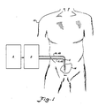
- a patient is illustrated at 10 having a continuous flow peritoneal dialysis catheter 12 implanted in the peritoneal membrane 14 of the patient.
- the implanted catheter is connected to suitable tubing 16 and 18 which is then, in turn, connected to a continuous flow peritoneal dialysis system which includes a fluid supply system A and a fluid delivery control system B.
- the fluid delivery control system includes a single-pass circuit through the peritoneal cavity of the patient.
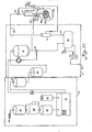
- the fluid supply system A includes a particle filter 20 to which a flow of tap water is directed. Water passing through the particle filter next goes to a reverse osmosis unit 22. From the reverse osmosis unit the water flows through a carbon filter 24 which takes out the chlorine in the water. From the carbon filter 24 the water flows into a conventional proportioning machine 26 which takes a 34:1 concentrate solution of non-sterile glucose and electrolytes from a supply 27 and mixes it with a proper amount of the purified water coming from the carbon filter 24.
- the dialysis solution from the proportioning and mixing unit 26 then passes to a micron particle filter 28 which separates out the non-dissolved particulate matter. Quite often the concentrate being mixed in the proportioning and mixing unit 26 includes some non-dissolved particulate matter.
- the micron filter 28 is preferably a one (1) micron filter which has an opening sufficient to remove the non-dissolved particulate matter. Both the Milipore and Gilman Manufacturing Companies manufacture a suitable micron filter.
- the fluid supply system A provides a properly mixed dialysis solution or dialysate which is non-sterile.
- the non-sterile fluid from the micron filter 28 is delivered to the continuous fluid delivery control system B.
- the non-sterile dialysis solution flows through a bacterial filter 30 whkch sterilizes the dialysis solution.
- the bacterial filter 30 is a conventional high volume bacterial filter which removes all the bacteria to provide a sterile dialysis solution.
- the fluid then flows to a head vessel 32 which provides a gravity feed means for feeding the sterilized dialysis fluid.
- the proportioning and mixing unit 26 includes a pump which is sufficient to pump the dialysis fluid into the head vessel.
- a by-pass valve 34 is connected to the outflow of the head vessel 32.
- the by-pass valve 34 provides a means for controlling the fluid level in the vessel and preventing the head vessel from overflowing. In the event that the head vessel begins to overflow or contains excess sterilized fluid coming from the fluid supply system A, the by-pass valve dumps the excess fluid to a storage container 36. It has been found that it is easier to dump the dialysate rather than start and stop the proportioning and mixing unit 26.
- a level monitor 38 provides a means for sensing the level of the dialysate fluid in the head vessel 32 and controlling the by-pass valve 34 in response to the fluid level.
- Switching means may also be provided responsive to the level monitor 38 to cut off the proportioning and mixing unit 26 in the event that the by-pass valve does not operate correctly and the fluid backs up excessively.
- An inflow/outflow directional valve 40 is connected to the by-pass valve 34 for receiving sterile dialysis fluid from the head vessel 32.
- the by-pass valve 34 delivers dialysis fluid to the directional valve 40 in an amount depending on the degree to which fluid is being by-passed to storage container 36.
- the by-pass valve 34 is controlled in a manner which will be more fully set forth hereinafter to vary the amount which is delivered to the directional valve 40.
- the by-pass valve 34 may be a throttling valve so that it has stepless variability for by-passing fluid from the line to the directional valve 40.
- An inflow line 42 (tubing 16) is connected to the directional valve 40 and to an inflow catheter 44 of the double peritoneal catheter 12.
- the dialysis fluid leaves the peritoneal cavity 14 through an outflow catheter 46 by way of an outflow line 48 (tubing 18) which is controlled and goes through the directional valve 40.
- the pressure monitor 50 controls the directional valve 40 to maintain a predetermined pressure or pressure range in the peritoneal cavity such that the membrane is properly distended at all times.
- the directional valve 40 is preferably a double flow valve to provide flows into the catheter and out of the catheter depending on the sensing by the pressure monitor 50.
- a separate inflow line and outflow line must be maintained through the valve 40 to ensure sterilization of the inflowing dialysis fluid.
- a modified single needle hemodialysis control valve manufactured by Vernitron Corporation is suitable. The modified valve is shown schematically in Figure 2 including an inflow passage 42 a and outflow passage 48 a controlled by a displaceable needle valve 43 which can be moved partially or fully to occlude either passage in response to abdominal pressure. Normally such a valve is pressure controlled but has only a single outlet line.
- the pressure monitor 50 will send a signal (electrical or mechanical) to the valve 40 to stop the inflow of the dialysis fluid while maintaining an outflow of the dialysis fluid so that the pressure is relieved.
- the needle 43 will occlude the inflow passage 42 a , completely in lieu of throttling, while the outflow passage 48 a will remain open to relieve pressure.
- the outflow of dialysis fluid will be cut off by moving the needle valve 43 proportionately to occlude the passage 48 a and the inflow will be continued so that the pressure is increased as desired. In either case, once the pressure is brought back to a desired value, the inflow and outflow of the dialysis fluid will be brought back to being equal.
- the pressure range which is normally desired in the abdominal cavity during dialysis is about 150 to 250cm/water. Any conventional commercially available pressure monitor operable in this range is suitable for the pressure monitor 50.
- the control of the valve 40 in response to pressure may be effected by any suitable means as is well within the purview of one skilled in the art. For example, electrical control may be effected with a single integrated circuit receiving the pressure signals and electrically controlling the needle valve 43.
- a flow monitor 54 is inserted in an outflow line 52 which goes from the directional valve 40 to the storage tank 36.
- the flow monitor 54 monitors the outflow and adjusts the flow through the by-pass valve 34 to the directional valve 40 so that the inflow provided by the by-pass valve 34 to the directional valve 40, is the same as the outflow from the peritoneal catheter.
- the directional valve 40 is in its normal setting, with the needle valve 43 in its neutral position, any change in the amount by-passed to the storage tank 36 by the valve 34 as controlled by the monitor 54 wil directly influence the amount delivered through the inflow passage 42 a .
- the valve 34 will be opened to by-pass more fluid and hence deliver less to the valve 40 thus matching the inflow to the decreased outflow.
- the pressure monitor 50 keeps check on the pressure inside the peritoneal cavity.
- the flow monitor 54 may be any suitable sensor such as an ultrasonic flow monitor which is conventionally used.
- the valve 40 as controlled by the pressure monitor 50, and the valve 34, as controlled by the flow monitor 54, provide flow control means for ensuring the proper volume and pressure of dialysis fluid in the peritoneal cavity.
- the needle valve 43 will be in its neutral position and the flow monitor will act to control the inflow in response to outflow by diverting fluid through the valve 34 instead of through the valve 40.
- the monitor 50 can effect relief by controlling the valve 40 as described above.
- the head vessel monitor 38 is independent of the pressure and flow regulating system.
- the directional valve 40 could also be a throttling valve instead of an on/off valve. In such a case, control of the by-pass valve 34 may not be necessary.
- the inflow line 42 and the outflow line 48 are connected to the inflow catheter 44 and the outflow catheter 46 by conventional means. This connection is made at the beginning of dialysis and disconnected at the end in a conventional manner.
- a drain pump 56 drains the dialysis fluid in the drain storage container 36 whenever a high level is reached.
- the fluid is drained into a drain 58 where it is drained away.
- a fluid level detector 60 provided which controls the operation of the pump 56.
- the aforedescribed drain apparatus provides a disposal means for the dialysis fluid which completes the open, single-pass circuit.
- the pressure monitor 50 provides a means for sensing the pressure in the abdomen of the patient.
- the abdomen has a particular pressure, for example, at two litres, that is comfortable. If, for example, one litre is accumulated in the abdominal area, the inner abdominal area is caused to expand by fifty percent and this results in a large degree of discomfort to the patient.
- the pressure monitor will sense a decrease in pressure. In this event, the pressure monitor will control the valve 40 which allows additional fluid to enter the cavity to bring the pressure back up to normal. In the event that the cavity becomes underdistended, the pressure will increase in pressure to cause the fluid to cut down the inflow and let the outflow of fluid continue until the pressure has stabilized.
- the invention can provide a highly advantageous process and system for continuous flow peritoneal dialysis where a single-open circuit is provided through the patient's peritoneal cavity.
- a sterilized peritoneal dialysis fluid is provided which is delivered through the cavity in such a manner that the volume and pressure of the fluid are controlled so that proper distention of the membrane occurs for patient comfort and dialysis efficiency.
- the high rate of fluid flow through the peritoneal cavity is advantageous in that the high rate of circulation increases dialysis efficiency.
- the line from the bacterial filter 30 to the head vessel 32 will be a disposable presterilized line of tubing.
- the head vessel 32 will be provided with a sterilized liner which is disposable and connected to presterilized tubing which connects the interior of the liner to the by-pass valve 34.
- the by-pass valve 34 will have three legs of disposable tubing in a Y-shape. The lower Y-leg of the disposable valve will be connected to the disposal storage tank 36.
- the actuator of the valve 34 will be external of the sterilized valve passages and will act upon the Y-leg of the valve passages leading to the disposal tank 36 to occlude the passage more or less in order to divert more or less fluid from the inflow/outflow directional valve 40.
- the inflow/outflow directional valve 40 will be a unit where the valve element 43 is external of tubing which passes through the passages 42 a and 48 a .
- the fluid passing through the tubing goes through the valve passages out of contact with any part of the valve so that the valve never has to be sterilized itself.
- the tubing going through the valve passage 42 a and connected to the inflow catheter 44 will be disposable.
- the tubing 48 coming from the outflow catheter 46 and through the outflow passage 48 a will likewise be presterilized and disposable as well as the outflow line 52.
- the pressure monitor 50 will preferably be designed to accept a length of presterilized tubing and sense the pressure of the fluid in the tubing without actually making contact with the fluid so that the pressure monitor may be interchanged with disposable tubing.
- the flow monitor 54 being of an ultrasonic type flow monitor likewise accepts a length of tubing through the flow monitor and will not ever contact the fluid.
- the entire set of tubing from the bacterial filter 30, through the head vessel 32, and including its liner, the tubing from the head vessel 32 to the valve 34 and including its "Y" tubing passages, and the remainder of the tubing passing through the valve 40, and to the catheter 12 will be a preformed preglued and presterilized unit.
- a separate preformed presterilized and preconnected section of disposable tubing will include the tubing connected to the outflow catheter 46 passing through the flow monitor 50, the outflow passage 48 a of the valve 40, and the flow monitor 54, and provided with a terminal connector which may be connected in the disposal tank 36. This will avoid the expense and time of cleaning and sterilizing valves, monitors, and fittings.
- Figure 3 illustrates an alternate embodiment wherein means for maintaining a prescribed volume of fluid in the peritoneal cavity is provided by fluid volume monitors, rather than fluid pressure monitors as illustrated in Figure 2, which sense a function of the volume of fluid in the cavity and control volume in accordance with differential flow in and out of the cavity.
- an ultrasonic flow monitor 61 disposed in the infeed line 42 for monitoring the flow of fluid in the inflow catheter 44.
- a second ultrasonic flow monitor 63 is disposed in the outflow line 48 connected to the outflow catheter 46.
- the outflow drainline 52 flows from the flow monitor 63 to the drain tank 36.
- a second conventional control valve 68 is disposed in the infeed line 42 upstream of the flow monitor 61. The monitors 61 and 63 thus sense a function of the volume of fluid in the cavity.
- the control valves 64 and 68 may be controlled by any suitable process controller 66 in a conventional manner as is well within the skill of one in the art.
- the sensor 62 provides a second means for monitoring fluid volume, in particular dangerous levels of fluid volume.
- the flow monitor 61 senses the amount of fluid flowing into the peritoneal cavity 14, and the outflow monitor 63 senses the amount of outflow fluid leaving the peritoneal cavity 14. These amounts are fed to the controller 66.
- the controller 66 compares the amounts of fluid flowing in the respective flow monitors and controls the valves 64, 68 to maintain a prescribed volume of fluid in the peritoneal cavity during dialysis.
- the prescribed amount can be varied in a conventional manner by input to the controller.
- the prescribed volume of fluid maintained in the peritoneal cavity 14 keeps the peritoneal cavity properly distended during dialysis.
- valve 64 will be closed. If the difference in volumetric flows between the flow monitors 61 and 63 indicates that too much fluid is being delivered to the peritoneal cavity 14, the valve 68 will be cut off. It is also possible that throttling valves may be utilized at 68 and 64 to control the flow in a more continuous manner.
- the ultrasonic level monitor 62 is disposed appropriately in the peritoneal cavity 14. If the volume of fluid in peritoneal cavity 14 should drop below the prescribed volume as sensed by the monitor 62, the controller 66 closes off the valve 64 to build up the volume of fluid in the peritoneal cavity 14. If the ultrasonic monitor 62 senses too large an amount of dialysis fluid in the peritoneal cavity 14, the alarm circuit 67 is triggered to produce an audible alarm and the valve 68 is closed to prevent any further fluid delivery.
- the head vessel monitor 38 operates as described previously to control the valve 34 in a manner such that the level of fluid in the vessel 32 is maintained at a desired level.
- FIG 3A illustrates a still further embodiment of the invention wherein a single catheter 70 is utilized in place of the double catheter illustrated in Figures 2 and 3 in a continuous cyclic flow.
- the inflow line 42 coming from the flow monitor 61 enters an inflow passage 42 a of a directional valve 69.
- the directional valve 69 may be identical to the directional valve 40 illustrated in Figure 2.
- the inflow passage 42 a is connected to an outflow passage 72 which is connected directly to the catheter 70.
- There is a parallel line 72 a which is connected to the passage 72 and to an outflow passage 48 a of the directional valve 69.
- a needle 69 a of the directional valve 69 may be used to occlude and close either the passage 42 a or the passage 48 a selectively.
- the remaining system is essentially the same as Figure 3 except that the valve 64 in Figure 3 is no longer needed since the directional valve 69 controls the outflow from the catheter 70 through the outflow passage 48 a .
- the directional valve 69 will control the inflow and outflow from the catheter by closing one passage while opening the other.
- the directional valve 69 will be controlled by a controller 66 which may be a conventional microprocessor.
- the flow monitors 61 and 63 have inputs connected to the controller 66. when a prescribed amount of fluid has flowed into the peritoneal cavity and abdomen, as sensed by the flow monitor 61, the directional valve 69 will be controlled to close the inflow passag 42 a and open the outflow passage 48 a .
- the directional valve 69 When the prescribed amount of fluid has flowed out of the abdomen, as sensed by the flow monitor 63, the directional valve 69 will be controlled to close the outflow passage 48 a and open the inflow passage 42 a . In this continuous but cyclic manner, the dialysis fluid from the continuous source A, as delivered to the head vessel 32, will be delivered through the catheter 70. Sufficient time will exist for the dialysis fluid in the peritoneal cavity to remove the water soluble metabolites. The flow will be continuous and cyclic through the single-pass open circuit from the head vessel 32, to peritoneal cavity 14, and to disposal 36.
Landscapes
- Health & Medical Sciences (AREA)
- Urology & Nephrology (AREA)
- Heart & Thoracic Surgery (AREA)
- Emergency Medicine (AREA)
- Anesthesiology (AREA)
- Engineering & Computer Science (AREA)
- Vascular Medicine (AREA)
- Biomedical Technology (AREA)
- Hematology (AREA)
- Life Sciences & Earth Sciences (AREA)
- Animal Behavior & Ethology (AREA)
- General Health & Medical Sciences (AREA)
- Public Health (AREA)
- Veterinary Medicine (AREA)
- External Artificial Organs (AREA)
Priority Applications (4)
| Application Number | Priority Date | Filing Date | Title |
|---|---|---|---|
| US06/629,130 US4586920A (en) | 1984-07-09 | 1984-07-09 | Continuous flow peritoneal dialysis system and method |
| DE8686303335T DE3680526D1 (de) | 1986-05-01 | 1986-05-01 | Vorrichtung zur peritonealen dialyse im staendigen strom. |
| EP86303335A EP0243547B1 (de) | 1986-05-01 | 1986-05-01 | Vorrichtung zur peritonealen Dialyse im ständigen Strom |
| AT86303335T ATE65416T1 (de) | 1986-05-01 | 1986-05-01 | Vorrichtung zur peritonealen dialyse im staendigen strom. |
Applications Claiming Priority (1)
| Application Number | Priority Date | Filing Date | Title |
|---|---|---|---|
| EP86303335A EP0243547B1 (de) | 1986-05-01 | 1986-05-01 | Vorrichtung zur peritonealen Dialyse im ständigen Strom |
Publications (2)
| Publication Number | Publication Date |
|---|---|
| EP0243547A1 true EP0243547A1 (de) | 1987-11-04 |
| EP0243547B1 EP0243547B1 (de) | 1991-07-24 |
Family
ID=8195994
Family Applications (1)
| Application Number | Title | Priority Date | Filing Date |
|---|---|---|---|
| EP86303335A Expired - Lifetime EP0243547B1 (de) | 1984-07-09 | 1986-05-01 | Vorrichtung zur peritonealen Dialyse im ständigen Strom |
Country Status (3)
| Country | Link |
|---|---|
| EP (1) | EP0243547B1 (de) |
| AT (1) | ATE65416T1 (de) |
| DE (1) | DE3680526D1 (de) |
Cited By (12)
| Publication number | Priority date | Publication date | Assignee | Title |
|---|---|---|---|---|
| EP0498382A1 (de) * | 1991-02-08 | 1992-08-12 | Alan M. Peabody | System zur kontinuierlichen Peritonaldialyse |
| WO1992018048A1 (fr) * | 1991-04-23 | 1992-10-29 | Viktor Anatolievich Sagatovich | Procede et installation de dialyse peritoneale |
| US5338293A (en) * | 1991-02-18 | 1994-08-16 | Gambro Ab | Set of tubes for peritoneal dialysis |
| WO1996037243A1 (en) * | 1995-05-23 | 1996-11-28 | Baxter International Inc. | Portable pump apparatus for continuous ambulatory peritoneal dialysis and a method for providing same |
| EP0943369A1 (de) * | 1998-03-07 | 1999-09-22 | Fresenius Medical Deutschland GmbH | Einrichtung zur Bereitstellung von Dialysierflüssigkeit mit einer Einrichtung zur Überwachung ausgewählter Parameter der Dialysierflüssigkeit und Verfahren zur Überwachung ausgewählter Parameter der Dialysierflüssigkeit bei einer Dialysebehandlung |
| EP0954244A4 (de) * | 1994-07-01 | 1999-11-10 | ||
| US9764074B1 (en) | 2002-07-19 | 2017-09-19 | Baxter International Inc. | Systems and methods for performing dialysis |
| US10646634B2 (en) | 2008-07-09 | 2020-05-12 | Baxter International Inc. | Dialysis system and disposable set |
| US10980931B2 (en) | 2001-11-13 | 2021-04-20 | Baxter International Inc. | System, method, and composition for removing uremic toxins in dialysis processes |
| US11400193B2 (en) | 2008-08-28 | 2022-08-02 | Baxter International Inc. | In-line sensors for dialysis applications |
| US11495334B2 (en) | 2015-06-25 | 2022-11-08 | Gambro Lundia Ab | Medical device system and method having a distributed database |
| US11516183B2 (en) | 2016-12-21 | 2022-11-29 | Gambro Lundia Ab | Medical device system including information technology infrastructure having secure cluster domain supporting external domain |
Families Citing this family (2)
| Publication number | Priority date | Publication date | Assignee | Title |
|---|---|---|---|---|
| ATE509645T1 (de) | 2002-07-19 | 2011-06-15 | Baxter Int | Vorrichtungen und verfahren zur peritonealdialyse |
| DK1523351T3 (da) | 2002-07-19 | 2010-04-26 | Baxter Int | System til peritonealdialyse |
Citations (6)
| Publication number | Priority date | Publication date | Assignee | Title |
|---|---|---|---|---|
| US3545438A (en) * | 1968-02-12 | 1970-12-08 | Sarns Inc | Intermittent dialysis method and apparatus therefor |
| DE2149040A1 (de) * | 1970-10-01 | 1972-04-06 | Tecna Corp | Verfahren und Einrichtung zur peritonalen Dialyse im staendigen Strom |
| US3709222A (en) * | 1970-12-28 | 1973-01-09 | Sarns Inc | Method and apparatus for automatic peritoneal dialysis |
| FR2371931A1 (fr) * | 1976-11-24 | 1978-06-23 | Abg Semca | Perfectionnements a la dialyse peritoneale |
| US4338190A (en) * | 1976-02-13 | 1982-07-06 | A. T. Ramot Plastics Ltd. | Peritoneal artificial kidney |
| EP0088900A2 (de) * | 1982-02-16 | 1983-09-21 | Fresenius AG | Vorrichtung zum Reinigen des Blutes von Stoffwechselprodukten |
-
1986
- 1986-05-01 EP EP86303335A patent/EP0243547B1/de not_active Expired - Lifetime
- 1986-05-01 DE DE8686303335T patent/DE3680526D1/de not_active Expired - Lifetime
- 1986-05-01 AT AT86303335T patent/ATE65416T1/de not_active IP Right Cessation
Patent Citations (6)
| Publication number | Priority date | Publication date | Assignee | Title |
|---|---|---|---|---|
| US3545438A (en) * | 1968-02-12 | 1970-12-08 | Sarns Inc | Intermittent dialysis method and apparatus therefor |
| DE2149040A1 (de) * | 1970-10-01 | 1972-04-06 | Tecna Corp | Verfahren und Einrichtung zur peritonalen Dialyse im staendigen Strom |
| US3709222A (en) * | 1970-12-28 | 1973-01-09 | Sarns Inc | Method and apparatus for automatic peritoneal dialysis |
| US4338190A (en) * | 1976-02-13 | 1982-07-06 | A. T. Ramot Plastics Ltd. | Peritoneal artificial kidney |
| FR2371931A1 (fr) * | 1976-11-24 | 1978-06-23 | Abg Semca | Perfectionnements a la dialyse peritoneale |
| EP0088900A2 (de) * | 1982-02-16 | 1983-09-21 | Fresenius AG | Vorrichtung zum Reinigen des Blutes von Stoffwechselprodukten |
Cited By (19)
| Publication number | Priority date | Publication date | Assignee | Title |
|---|---|---|---|---|
| EP0498382A1 (de) * | 1991-02-08 | 1992-08-12 | Alan M. Peabody | System zur kontinuierlichen Peritonaldialyse |
| US5338293A (en) * | 1991-02-18 | 1994-08-16 | Gambro Ab | Set of tubes for peritoneal dialysis |
| WO1992018048A1 (fr) * | 1991-04-23 | 1992-10-29 | Viktor Anatolievich Sagatovich | Procede et installation de dialyse peritoneale |
| EP0954244A4 (de) * | 1994-07-01 | 1999-11-10 | ||
| US6196992B1 (en) | 1995-05-23 | 2001-03-06 | Baxter International Inc. | Portable pump apparatus for continuous ambulatory peritoneal dialysis and a method for providing same |
| US5873853A (en) * | 1995-05-23 | 1999-02-23 | Baxter International Inc. | Portable pump apparatus for continuous ambulatory peritoneal dialysis and a method for providing same |
| US5984891A (en) * | 1995-05-23 | 1999-11-16 | Baxter International Inc. | Portable pump apparatus for continuous ambulatory peritoneal dialysis and a method for providing same |
| WO1996037243A1 (en) * | 1995-05-23 | 1996-11-28 | Baxter International Inc. | Portable pump apparatus for continuous ambulatory peritoneal dialysis and a method for providing same |
| EP0943369A1 (de) * | 1998-03-07 | 1999-09-22 | Fresenius Medical Deutschland GmbH | Einrichtung zur Bereitstellung von Dialysierflüssigkeit mit einer Einrichtung zur Überwachung ausgewählter Parameter der Dialysierflüssigkeit und Verfahren zur Überwachung ausgewählter Parameter der Dialysierflüssigkeit bei einer Dialysebehandlung |
| US10980931B2 (en) | 2001-11-13 | 2021-04-20 | Baxter International Inc. | System, method, and composition for removing uremic toxins in dialysis processes |
| US10363352B2 (en) | 2002-07-19 | 2019-07-30 | Baxter International Inc. | Disposable set and system for dialysis |
| US9814820B2 (en) | 2002-07-19 | 2017-11-14 | Baxter International Inc. | Weight-controlled sorbent system for hemodialysis |
| US9764074B1 (en) | 2002-07-19 | 2017-09-19 | Baxter International Inc. | Systems and methods for performing dialysis |
| US11235094B2 (en) | 2002-07-19 | 2022-02-01 | Baxter International Inc. | System for peritoneal dialysis |
| US10646634B2 (en) | 2008-07-09 | 2020-05-12 | Baxter International Inc. | Dialysis system and disposable set |
| US11400193B2 (en) | 2008-08-28 | 2022-08-02 | Baxter International Inc. | In-line sensors for dialysis applications |
| US11495334B2 (en) | 2015-06-25 | 2022-11-08 | Gambro Lundia Ab | Medical device system and method having a distributed database |
| US12548646B2 (en) | 2015-06-25 | 2026-02-10 | Gambro Lundia Ab | Medical device system and method having a distributed database |
| US11516183B2 (en) | 2016-12-21 | 2022-11-29 | Gambro Lundia Ab | Medical device system including information technology infrastructure having secure cluster domain supporting external domain |
Also Published As
| Publication number | Publication date |
|---|---|
| ATE65416T1 (de) | 1991-08-15 |
| DE3680526D1 (de) | 1991-08-29 |
| EP0243547B1 (de) | 1991-07-24 |
Similar Documents
| Publication | Publication Date | Title |
|---|---|---|
| US4747822A (en) | Continuous flow peritoneal dialysis system and method | |
| US4718890A (en) | Continuous flow peritoneal dialysis system and method | |
| US4586920A (en) | Continuous flow peritoneal dialysis system and method | |
| EP0243547B1 (de) | Vorrichtung zur peritonealen Dialyse im ständigen Strom | |
| JP6581609B2 (ja) | 腹膜透析を実施するためのシステムおよび方法 | |
| KR100838383B1 (ko) | 주입 용액 시스템용 밸브 기구 | |
| DE60120922T2 (de) | Vorrichtung zur überwachung und steuerung von peritonealdialysebehandlungen | |
| US20040049288A1 (en) | Prosthesis for internal peritoneal dialysis and method of providing peritoneal dialysis | |
| MX2011000977A (es) | Sistema de dialisis con dispositivo de regulacion de flujo. | |
| DE102009037917B4 (de) | Schlauchset für eine Vorrichtung zur Blutbehandlung und Vorrichtung zur Blutbehandlung mit einem Schlauchset | |
| US20130292313A1 (en) | Apparatus for extracorporeal blood treatment | |
| JPH06104119B2 (ja) | 調節された流体を用いて医学的処理を制御する装置 | |
| JPH04327857A (ja) | 腹膜透析装置 | |
| EP3431119B1 (de) | Vorrichtung zur extrakorporalen behandlung von blut | |
| EP4448045B1 (de) | Peritonealdialysesystem mit einem patientenleitungsfilter mit luftrückführung | |
| JPH06104120B2 (ja) | 連続流れによる腹膜透析装置 | |
| US20250009950A1 (en) | Peritoneal dialysis system including a patient line filter having a tubular membrane | |
| US20250009949A1 (en) | Peritoneal dialysis system having a capillary patient line filter | |
| JP5995221B6 (ja) | 腹膜透析を実施するためのシステムおよび方法 | |
| CN119183388A (zh) | 具有低容积腹膜透析患者填充温度控制的透析系统 |
Legal Events
| Date | Code | Title | Description |
|---|---|---|---|
| PUAI | Public reference made under article 153(3) epc to a published international application that has entered the european phase |
Free format text: ORIGINAL CODE: 0009012 |
|
| AK | Designated contracting states |
Kind code of ref document: A1 Designated state(s): AT BE CH DE FR GB IT LI LU NL SE |
|
| 17P | Request for examination filed |
Effective date: 19880415 |
|
| 17Q | First examination report despatched |
Effective date: 19891004 |
|
| GRAA | (expected) grant |
Free format text: ORIGINAL CODE: 0009210 |
|
| ITF | It: translation for a ep patent filed | ||
| AK | Designated contracting states |
Kind code of ref document: B1 Designated state(s): AT BE CH DE FR GB IT LI LU NL SE |
|
| REF | Corresponds to: |
Ref document number: 65416 Country of ref document: AT Date of ref document: 19910815 Kind code of ref document: T |
|
| REF | Corresponds to: |
Ref document number: 3680526 Country of ref document: DE Date of ref document: 19910829 |
|
| ET | Fr: translation filed | ||
| PLBE | No opposition filed within time limit |
Free format text: ORIGINAL CODE: 0009261 |
|
| STAA | Information on the status of an ep patent application or granted ep patent |
Free format text: STATUS: NO OPPOSITION FILED WITHIN TIME LIMIT |
|
| 26N | No opposition filed | ||
| EPTA | Lu: last paid annual fee | ||
| EAL | Se: european patent in force in sweden |
Ref document number: 86303335.3 |
|
| REG | Reference to a national code |
Ref country code: GB Ref legal event code: IF02 |
|
| PGFP | Annual fee paid to national office [announced via postgrant information from national office to epo] |
Ref country code: BE Payment date: 20020403 Year of fee payment: 17 |
|
| PGFP | Annual fee paid to national office [announced via postgrant information from national office to epo] |
Ref country code: LU Payment date: 20020404 Year of fee payment: 17 |
|
| PGFP | Annual fee paid to national office [announced via postgrant information from national office to epo] |
Ref country code: AT Payment date: 20020514 Year of fee payment: 17 |
|
| PGFP | Annual fee paid to national office [announced via postgrant information from national office to epo] |
Ref country code: NL Payment date: 20020531 Year of fee payment: 17 |
|
| PGFP | Annual fee paid to national office [announced via postgrant information from national office to epo] |
Ref country code: CH Payment date: 20020724 Year of fee payment: 17 |
|
| PG25 | Lapsed in a contracting state [announced via postgrant information from national office to epo] |
Ref country code: LU Free format text: LAPSE BECAUSE OF NON-PAYMENT OF DUE FEES Effective date: 20030501 Ref country code: AT Free format text: LAPSE BECAUSE OF NON-PAYMENT OF DUE FEES Effective date: 20030501 |
|
| PG25 | Lapsed in a contracting state [announced via postgrant information from national office to epo] |
Ref country code: LI Free format text: LAPSE BECAUSE OF NON-PAYMENT OF DUE FEES Effective date: 20030531 Ref country code: CH Free format text: LAPSE BECAUSE OF NON-PAYMENT OF DUE FEES Effective date: 20030531 Ref country code: BE Free format text: LAPSE BECAUSE OF NON-PAYMENT OF DUE FEES Effective date: 20030531 |
|
| BERE | Be: lapsed |
Owner name: *PEABODY ALAN M. Effective date: 20030531 |
|
| PG25 | Lapsed in a contracting state [announced via postgrant information from national office to epo] |
Ref country code: NL Free format text: LAPSE BECAUSE OF NON-PAYMENT OF DUE FEES Effective date: 20031201 |
|
| REG | Reference to a national code |
Ref country code: CH Ref legal event code: PL |
|
| NLV4 | Nl: lapsed or anulled due to non-payment of the annual fee |
Effective date: 20031201 |
|
| PG25 | Lapsed in a contracting state [announced via postgrant information from national office to epo] |
Ref country code: IT Free format text: LAPSE BECAUSE OF NON-PAYMENT OF DUE FEES;WARNING: LAPSES OF ITALIAN PATENTS WITH EFFECTIVE DATE BEFORE 2007 MAY HAVE OCCURRED AT ANY TIME BEFORE 2007. THE CORRECT EFFECTIVE DATE MAY BE DIFFERENT FROM THE ONE RECORDED. Effective date: 20050501 |
|
| PGFP | Annual fee paid to national office [announced via postgrant information from national office to epo] |
Ref country code: GB Payment date: 20050503 Year of fee payment: 20 |
|
| PGFP | Annual fee paid to national office [announced via postgrant information from national office to epo] |
Ref country code: FR Payment date: 20050509 Year of fee payment: 20 |
|
| PGFP | Annual fee paid to national office [announced via postgrant information from national office to epo] |
Ref country code: SE Payment date: 20050517 Year of fee payment: 20 |
|
| PGFP | Annual fee paid to national office [announced via postgrant information from national office to epo] |
Ref country code: DE Payment date: 20050713 Year of fee payment: 20 |
|
| PG25 | Lapsed in a contracting state [announced via postgrant information from national office to epo] |
Ref country code: GB Free format text: LAPSE BECAUSE OF EXPIRATION OF PROTECTION Effective date: 20060430 |
|
| REG | Reference to a national code |
Ref country code: GB Ref legal event code: PE20 |
|
| EUG | Se: european patent has lapsed |