EP0243519A2 - Übernahtnähmaschine - Google Patents
Übernahtnähmaschine Download PDFInfo
- Publication number
- EP0243519A2 EP0243519A2 EP86105888A EP86105888A EP0243519A2 EP 0243519 A2 EP0243519 A2 EP 0243519A2 EP 86105888 A EP86105888 A EP 86105888A EP 86105888 A EP86105888 A EP 86105888A EP 0243519 A2 EP0243519 A2 EP 0243519A2
- Authority
- EP
- European Patent Office
- Prior art keywords
- knife
- movable
- movable portion
- bed frame
- fixed knife
- Prior art date
- Legal status (The legal status is an assumption and is not a legal conclusion. Google has not performed a legal analysis and makes no representation as to the accuracy of the status listed.)
- Granted
Links
Images


Classifications
-
- D—TEXTILES; PAPER
- D05—SEWING; EMBROIDERING; TUFTING
- D05B—SEWING
- D05B1/00—General types of sewing apparatus or machines without mechanism for lateral movement of the needle or the work or both
- D05B1/08—General types of sewing apparatus or machines without mechanism for lateral movement of the needle or the work or both for making multi-thread seams
- D05B1/18—Seams for protecting or securing edges
- D05B1/20—Overedge seams
Definitions
- the present invention relates to an overlock machine used to overcast the edge of a cloth.
- Figs. 9 and 10 show two prior art overlock machines. It comprises a bed frame 1 and a bed 2. (Fig. 9) The bed is formed with an opening 4 covered by a throat plate 3 which can be opened. A fixed knife 5 is mounted on a left side wall 6 of the bed frame 1. An elevatable rod 8 is elevatably mounted on guides 9 and 10. A movable knife 11 is fixed to the top end of the elevatable rod 8. A blade 12 on the fixed knife 5 cooperates with a blade 13 on the movable knife 11 to cut the edge of a cloth evenly.
- the guides 9, 10 have shafts 14, 15, respectively, which are mounted on the left side wall 6 of the bed frame 1 so as to be retractable.
- the guide 9 is biassed leftwardly by a spring to press the movable knife 11 against the right side of the fixed knife 5.
- a roller 17 is coupled to a block 16 fixedly mounted on the elevatable rod 8.
- a forked lever 18 coupled to a moving part of the machine engages the roller 17, so that the elevatable rod 8 will move up and down as the machine is operated.
- the fixed knife 5 is fixed to a fitting 20 provided under the bed 2.
- the movable knife 11 is fixed to one end of a shaft 24 turnably and slidably mounted on a boss 23 which is provided at a front end of a swivel arm 22 having its rear portion mounted on a machine body 21 on the bed 2.
- a spring 25 in the boss 23 urges the movable knife 11 leftwardly to press it against the righthand side face of the fixed knife 5.
- the shaft 24 has a pin 28 extending radially and the boss 23 is formed with a notch 29 to receive the pin 28.
- the movable knife 11 extends downwardly and is pressed by the resilience of the spring 25 against the fixed knife 5.
- a knob 30 at the righthand end of the shaft 24 is operated to pull the shaft 24 rightwardly to disengage the pin 28 from the notch 29 and is turned, the movable knife 11 extends forwardly with the pin 28 butting on the right side of the boss 23, as shown in Fig. 8.
- a lower looper 32 is fixed to the top of a swivel lever 34 mounted on a shaft 33 projecting from the bed frame 1.
- the lower looper 32 is formed with a thread hole 35 at its lefthand end viewing from the operator side. The thread is passed through the hole 35, in and along a thread groove 36, and into a thread hole 37 at the other end of the looper 32.
- the lefthand end of the bed frame 1 is comprised of an auxiliary bed 40 which can be opened.
- a front cover (not shown) is firstly opened and the auxiliary bed 40 is then opened.
- the thread from a bobbin (not shown) is passed through a thread tension adjusting assembly and a thread guide (both not shown), through a thread guide 41, under the fixed knife 5 and the throad plate 3, or through an opening 42 in the left side wall 6 of the bed frame 1, and pulled out in rear of the lower looper 32.
- the thread is then passed through the hole 35 of the lower looper 32, guided in the groove 36, and passed through the hole 37 at tip of the lower looper.
- the setting of a thread through the lower looper 32 is very troublesome.
- the fixed knife 5 the parts for securing the fixed knife, the bed frame for supporting it, and the bed portion supporting the throat plate 3 and extending forwardly obstruct the sight of the operator to the lower looper 32 and the access of his fingers to it. This makes the thread setting on the lower looper very troublesome and time-consuming.
- An object of the present invention is to provide an overlock machine which obviates the abovesaid shortcomings.
- the parts and members obstructing the work for setting a thread through the lower looper which are carried by the movable portion of the bed frame, are adapted to be moved to an inoperative position. Only the fixed knife (in the second embodiment), or both the fixed knife and the movable knife (in the first embodiment) are moved from the front of the lower looper to allow the sight of, and access to, the lower looper. Thus, the operator is given a clear sight of the lower looper and an easy access of his fingers to it. This facilitates the thread setting very much.
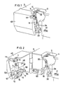
- the first embodiment shown in Figs. 1 - 4 provides an improvement of the prior art overlock machine shown in Fig. 9.
- Both the fixed knife 5 and the movable knife 11 are mounted on a movable portion 45 of a bed frame 1.
- the movable portion is mounted so as to be pivotable around a shaft 46 shown in Fig. 3.
- a fixed knife 5 is bolted to a mounting surface 44 of the movable portion 45.
- a movable knife 11 is mounted on an elevatable rod 8 (Fig. 3).
- a shaft 14 of a guide 9 on the elevatable rod 8 is retractably mounted in a mounting portion 48 in the movable portion 45.
- the shaft 14 is biassed by a spring 49 mounted thereon in a hole formed in the shaft at its rear end and supported by a spring support 50 secured to the rear end of the shaft 14 in such a direction as to press the movable knife 11 against the fixed knife 5.
- a forked lever 18 has its middle portion supported by a shaft 51 and its rear end coupled to a link 53 which is moved up and down by a lower shaft 52 of the machine through an eccentric (Fig. 4).
- the forked lever 18 has its front portion forked to receive a roller 17 disposed in the mov able portion 45.
- a hook 55 (Figs. 2 - 4) is secured to the inner end of a transverse shaft 57 turnably mounted in the movable portion 45.
- a knob 58 is secured to the outer end of the transverse shaft 57.
- the hook 55 is adapted to engage an engagement piece 60 fixed in the bed frame 1 (Fig. 2).
- the knob 58 By operating the knob 58, the hook 55 can be disengaged from the engagement piece 60.
- the hook 55 engages the engagement piece 60 and the forked lever 18 engages the roller 17 on the elevatable rod 8.
- the forked lever 18 will pivot up and down, so that the elevatable rod 8 and thus the movable knife 11 will move up and down.
- the knob 58 When passing a thread through the lower looper 32, the knob 58 is operated to disengage the hook 55 from the engagement piece 60. Now, the movable portion 45 can be swung to its inoperative position as shown in Fig. 2. This allows the sight of and access to the lower looper 32. Setting a thread on it is now very easy.
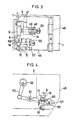
- the second embodiment shown in Figs. 5 and 6 provides an improvement of the prior art overlock machine shown in Fig. 10.
- the movable knife 11 is supported in the same manner as in the prior art overlock machine, as shown in Figs. 7 and 8 and described before. Only the fixed knife 5 is secured to a mounting plate 47 secured to the movable portion 45.
- a hook 55 and a knob 58 are fixedly mounted on a transverse shaft 57 rotatably mounted on the movable portion 45, as in the first embodiment.
- the hook 55 is adapted to engage an engagement piece 60 secured to the bed frame 1.
- the hook 55 engages the engagement piece 60.
- the movable knife 11 With the movable knife 11 extending downwardly and the pin 28 engaged in the notch 29 in the boss 23 as shown in Fig. 7, the movable knife 11 is pressed against the fixed knife 5, as shown in Fig. 5, and moves up and down, as the machine operates, to cut the cloth edge evenly.
- the shaft 24 is pulled with the knob 30 against the bias of the spring 25 to disengage the pin 28 from the notch 29 and is turned to the position shown in Fig. 8 where the movable knife 11 faces to the front.
- the movable portion 45 is adapted to be pivoted sidewise, it may be adapted to be pivoted downwardly to be pulled out, or to be moved to its inoperative position in any other way.
- a forked lever 18 is coupled to the machine body and the roller 17 is used to move the movable knife up and down
- a roller may be used instead of the forked lever and a forked lever may be used instead of the roller.
Landscapes
- Engineering & Computer Science (AREA)
- Textile Engineering (AREA)
- Sewing Machines And Sewing (AREA)
Priority Applications (3)
| Application Number | Priority Date | Filing Date | Title |
|---|---|---|---|
| US06/856,212 US4649841A (en) | 1986-04-28 | 1986-04-28 | Swingable mounting for a trimmer in a overlock machine |
| DE8686105888T DE3673407D1 (de) | 1986-04-29 | 1986-04-29 | Uebernahtnaehmaschine. |
| EP19860105888 EP0243519B1 (de) | 1986-04-29 | 1986-04-29 | Übernahtnähmaschine |
Applications Claiming Priority (1)
| Application Number | Priority Date | Filing Date | Title |
|---|---|---|---|
| EP19860105888 EP0243519B1 (de) | 1986-04-29 | 1986-04-29 | Übernahtnähmaschine |
Publications (3)
| Publication Number | Publication Date |
|---|---|
| EP0243519A2 true EP0243519A2 (de) | 1987-11-04 |
| EP0243519A3 EP0243519A3 (en) | 1988-01-13 |
| EP0243519B1 EP0243519B1 (de) | 1990-08-08 |
Family
ID=8195093
Family Applications (1)
| Application Number | Title | Priority Date | Filing Date |
|---|---|---|---|
| EP19860105888 Expired EP0243519B1 (de) | 1986-04-28 | 1986-04-29 | Übernahtnähmaschine |
Country Status (2)
| Country | Link |
|---|---|
| EP (1) | EP0243519B1 (de) |
| DE (1) | DE3673407D1 (de) |
Cited By (1)
| Publication number | Priority date | Publication date | Assignee | Title |
|---|---|---|---|---|
| CN111945409A (zh) * | 2020-07-24 | 2020-11-17 | 佛山市源田床具机械有限公司 | 一种全自动锁边切边装置 |
Family Cites Families (2)
| Publication number | Priority date | Publication date | Assignee | Title |
|---|---|---|---|---|
| GB241433A (en) * | 1925-02-04 | 1925-10-22 | Union Special Machine Co | Improvements in sewing machines |
| US2636462A (en) * | 1949-10-19 | 1953-04-28 | Union Special Machine Co | Overedge sewing machine |
-
1986
- 1986-04-29 EP EP19860105888 patent/EP0243519B1/de not_active Expired
- 1986-04-29 DE DE8686105888T patent/DE3673407D1/de not_active Expired - Fee Related
Cited By (1)
| Publication number | Priority date | Publication date | Assignee | Title |
|---|---|---|---|---|
| CN111945409A (zh) * | 2020-07-24 | 2020-11-17 | 佛山市源田床具机械有限公司 | 一种全自动锁边切边装置 |
Also Published As
| Publication number | Publication date |
|---|---|
| EP0243519A3 (en) | 1988-01-13 |
| EP0243519B1 (de) | 1990-08-08 |
| DE3673407D1 (de) | 1990-09-13 |
Similar Documents
| Publication | Publication Date | Title |
|---|---|---|
| US4389952A (en) | Needle bar operated trimmer | |
| US4649841A (en) | Swingable mounting for a trimmer in a overlock machine | |
| US4977842A (en) | Overlock sewing machine with a threading mechanism for easily threading a looper | |
| US5931106A (en) | Buttonhole sewing machine, with a needle-thread clamp and cutter | |
| US4453481A (en) | Method and apparatus for cutting and tacking stitches | |
| JPS5940040B2 (ja) | ミシンにおけるステッチチェン用制御装置 | |
| EP0243519B1 (de) | Übernahtnähmaschine | |
| US5178084A (en) | Multiple needle chainstitch sewing machine | |
| US4796552A (en) | Latch tacker | |
| CA1264989A (en) | Overlock machine | |
| US4213411A (en) | Readily attachable and detachable sole plate for a sewing machine | |
| US4055127A (en) | Hem folding attachment | |
| US3967568A (en) | Thread cutter for blindstitch sewing machine | |
| US4248166A (en) | Sewing machine attachment | |
| US4850293A (en) | Sewing machine top cover thread trimmer | |
| US4825785A (en) | Latch tacker | |
| US4722289A (en) | Sewing machine | |
| US2717567A (en) | Presser foot supporting and operating means for sewing machines and the like | |
| JPH06102109B2 (ja) | オ−バロツクミシン | |
| US4269127A (en) | Trimming device for sewing machines | |
| JPS6242635B2 (de) | ||
| US4254719A (en) | Tape guiding accessory for sewing machines | |
| JP2939809B2 (ja) | ミシンの糸切断装置 | |
| US4785753A (en) | Latch tacker | |
| CN212426392U (zh) | 一种包缝机的剪线机构 |
Legal Events
| Date | Code | Title | Description |
|---|---|---|---|
| PUAI | Public reference made under article 153(3) epc to a published international application that has entered the european phase |
Free format text: ORIGINAL CODE: 0009012 |
|
| AK | Designated contracting states |
Kind code of ref document: A2 Designated state(s): CH DE FR GB LI NL SE |
|
| PUAL | Search report despatched |
Free format text: ORIGINAL CODE: 0009013 |
|
| AK | Designated contracting states |
Kind code of ref document: A3 Designated state(s): CH DE FR GB LI NL SE |
|
| 17P | Request for examination filed |
Effective date: 19880209 |
|
| 17Q | First examination report despatched |
Effective date: 19890411 |
|
| GRAA | (expected) grant |
Free format text: ORIGINAL CODE: 0009210 |
|
| AK | Designated contracting states |
Kind code of ref document: B1 Designated state(s): CH DE FR GB LI NL SE |
|
| PG25 | Lapsed in a contracting state [announced via postgrant information from national office to epo] |
Ref country code: NL Effective date: 19900808 Ref country code: LI Effective date: 19900808 Ref country code: FR Effective date: 19900808 Ref country code: CH Effective date: 19900808 |
|
| REF | Corresponds to: |
Ref document number: 3673407 Country of ref document: DE Date of ref document: 19900913 |
|
| REG | Reference to a national code |
Ref country code: CH Ref legal event code: PL |
|
| EN | Fr: translation not filed | ||
| NLV1 | Nl: lapsed or annulled due to failure to fulfill the requirements of art. 29p and 29m of the patents act | ||
| PG25 | Lapsed in a contracting state [announced via postgrant information from national office to epo] |
Ref country code: GB Effective date: 19910429 |
|
| PLBE | No opposition filed within time limit |
Free format text: ORIGINAL CODE: 0009261 |
|
| STAA | Information on the status of an ep patent application or granted ep patent |
Free format text: STATUS: NO OPPOSITION FILED WITHIN TIME LIMIT |
|
| 26N | No opposition filed | ||
| GBPC | Gb: european patent ceased through non-payment of renewal fee | ||
| EAL | Se: european patent in force in sweden |
Ref document number: 86105888.1 |
|
| PGFP | Annual fee paid to national office [announced via postgrant information from national office to epo] |
Ref country code: SE Payment date: 19960419 Year of fee payment: 11 |
|
| PGFP | Annual fee paid to national office [announced via postgrant information from national office to epo] |
Ref country code: DE Payment date: 19960620 Year of fee payment: 11 |
|
| PG25 | Lapsed in a contracting state [announced via postgrant information from national office to epo] |
Ref country code: SE Effective date: 19970430 |
|
| PG25 | Lapsed in a contracting state [announced via postgrant information from national office to epo] |
Ref country code: DE Free format text: LAPSE BECAUSE OF NON-PAYMENT OF DUE FEES Effective date: 19980101 |
|
| EUG | Se: european patent has lapsed |
Ref document number: 86105888.1 |