EP0243506B1 - Strahlungsrohrbrenner - Google Patents
Strahlungsrohrbrenner Download PDFInfo
- Publication number
- EP0243506B1 EP0243506B1 EP86906451A EP86906451A EP0243506B1 EP 0243506 B1 EP0243506 B1 EP 0243506B1 EP 86906451 A EP86906451 A EP 86906451A EP 86906451 A EP86906451 A EP 86906451A EP 0243506 B1 EP0243506 B1 EP 0243506B1
- Authority
- EP
- European Patent Office
- Prior art keywords
- tube
- gas
- burner
- combustion
- water
- Prior art date
- Legal status (The legal status is an assumption and is not a legal conclusion. Google has not performed a legal analysis and makes no representation as to the accuracy of the status listed.)
- Expired - Lifetime
Links
Images


Classifications
-
- F—MECHANICAL ENGINEERING; LIGHTING; HEATING; WEAPONS; BLASTING
- F23—COMBUSTION APPARATUS; COMBUSTION PROCESSES
- F23D—BURNERS
- F23D14/00—Burners for combustion of a gas, e.g. of a gas stored under pressure as a liquid
- F23D14/20—Non-premix gas burners, i.e. in which gaseous fuel is mixed with combustion air on arrival at the combustion zone
- F23D14/22—Non-premix gas burners, i.e. in which gaseous fuel is mixed with combustion air on arrival at the combustion zone with separate air and gas feed ducts, e.g. with ducts running parallel or crossing each other
- F23D14/24—Non-premix gas burners, i.e. in which gaseous fuel is mixed with combustion air on arrival at the combustion zone with separate air and gas feed ducts, e.g. with ducts running parallel or crossing each other at least one of the fluids being submitted to a swirling motion
-
- F—MECHANICAL ENGINEERING; LIGHTING; HEATING; WEAPONS; BLASTING
- F23—COMBUSTION APPARATUS; COMBUSTION PROCESSES
- F23C—METHODS OR APPARATUS FOR COMBUSTION USING FLUID FUEL OR SOLID FUEL SUSPENDED IN A CARRIER GAS OR AIR
- F23C6/00—Combustion apparatus characterised by the combination of two or more combustion chambers or combustion zones, e.g. for staged combustion
- F23C6/04—Combustion apparatus characterised by the combination of two or more combustion chambers or combustion zones, e.g. for staged combustion in series connection
- F23C6/045—Combustion apparatus characterised by the combination of two or more combustion chambers or combustion zones, e.g. for staged combustion in series connection with staged combustion in a single enclosure
-
- F—MECHANICAL ENGINEERING; LIGHTING; HEATING; WEAPONS; BLASTING
- F23—COMBUSTION APPARATUS; COMBUSTION PROCESSES
- F23C—METHODS OR APPARATUS FOR COMBUSTION USING FLUID FUEL OR SOLID FUEL SUSPENDED IN A CARRIER GAS OR AIR
- F23C7/00—Combustion apparatus characterised by arrangements for air supply
- F23C7/002—Combustion apparatus characterised by arrangements for air supply the air being submitted to a rotary or spinning motion
- F23C7/004—Combustion apparatus characterised by arrangements for air supply the air being submitted to a rotary or spinning motion using vanes
-
- F—MECHANICAL ENGINEERING; LIGHTING; HEATING; WEAPONS; BLASTING
- F23—COMBUSTION APPARATUS; COMBUSTION PROCESSES
- F23C—METHODS OR APPARATUS FOR COMBUSTION USING FLUID FUEL OR SOLID FUEL SUSPENDED IN A CARRIER GAS OR AIR
- F23C2203/00—Flame cooling methods otherwise than by staging or recirculation
- F23C2203/30—Injection of tempering fluids
Definitions
- This invention relates to a radiant tube burner comprising a combustion tube installed in a radiant tube, a primary air supply tube and a gas burner having a nozzle of the divergent flame type and coaxially placed in the combustion tube so that, in use, fuel gas coming out of the gas burner undergoes primary combustion by primary air supplied through the annular space between the gas burner and the combustion tube and further undergoes secondary combustion by secondary air supplied through the annular space between the combustion tube and the radiant tube.
- Such a burner is described, for instance, in JP-B2-52-29007.
- Embodiments of the present invention may provide a radiant tube burner in which high heat load primary combustion is caused to happen in satisfactory and stable way by swirling the primary air and soft secondary combustion takes place in a radiant tube, thereby making it possible to obtain low NO X .
- a radiant tube burner of the type described at the beginning characterised in that the gas burner is designed to be movable in the axial direction, primary air swirling vanes are located at the end of the burner, for forming a swirled flame, and an air damper is fitted on the primary air supply tube, which is connected to the combustion tube, for adjusting the ratio of primary air to secondary air.
- the flame temperature is reduced by means of adding atomized water into the combustion flame, thereby making it possible to obtain low NO X , while high heat load combustion is going on in satisfactory and stable way owing to the two- stage combustion described above.
- a water spray nozzle may be placed at the centre of the divergent flame type nozzle, the water nozzle being connected to an atomized water generator capable of supplying pressurized gas and additive water through an additive water transfer tube installed in the gas burner.
- the atomized water generator is composed of a cylinder having a conical hole to be connected to the additive water transfer tube, a recessed disk having grooves for the injection of pressurized gas and additive water and fitted to the said cylinder, and a housing for accommodating the cylinder and the disk.
- Embodiments of the present invention may also provide a radiant tube burner in which, in addition to the aforementioned features, the exhaust gas is used as atomizing medium, thereby accomplishing enhanced reduction of NOx while high heat load and low NO X combustion occurs due to the swirling of the primary air and addition of atomized water into the combustion flame.
- the atomized water generator may be connected to the exhaust gas pipe, while other parts remain the same as described above.
- low pressure fuel gas can be used as an atomizing medium, in which case the water atomizer is connected to the fuel gas while other parts remain the same as described in the preceding.
- an exhaust gas introducing tube and a water outflow nozzle may both be placed at the central portion of the divergent flame tube nozzle to utilise the kinetic energy of low pressure exhaust gas to atomize the water supplied from the additive water transfer tube.
- a gas burner 1 is coaxially placed with a combustion tube 2.
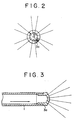
- a divergent flame type nozzle 3a (see Figures 2 and 3) is mounted at the end of the burner 1.
- a primary air supply tube 5 joins the rear end of the combustion tube 2 to form an integral piece extending coaxially with the burner 1.
- the primary air supply tube 5 has four rectangular ports 6 evenly spaced over the entire periphery thereof. The area of the inlet 6 can be changed by moving, with an operating rod 8 and a nut 9, a cylindrical air damper 7, into which the air supply tube 5 is loosely fitted.
- Primary air swirling vanes 10 having an angle within the range from 15 to 60° are secured on a retaining tube 11 at the front end of said burner 1, as shown in Figures 4 and 5.
- the combustion tube 2 and the primary air supply tube 5 are coaxially housed in a radiant tube 12.
- An air supply connection 13 is provided at the rear section of the radiant tube 12 in which the inlet ports 6 are located.
- An end cover 14 closes rear ends of the primary air supply tube 5 and radiant tube 12.
- the gas burner 1 is installed across said end cover 14 to extend rearward.
- Reference numeral 15 designates a pilot burner.
- the gas burner 1 extends movably through the end cover 14 in the axial direction within the range of the combustion tube 2 together with the pilot burner 15. Accordingly, the divergent flame type nozzle 3a is supported in the combustion tube 2 through the swirling vanes 10 so that the nozzle position is changeable.
- the set position L of the divergent flame type nozzle 3a is changeable within the range from 100 to 500 mm.
- the burner 1 is fixed by a bolt 16 attached on the end cover 14.
- the gas supplied to the gas burner 1 through the connection 4 is ejected from the divergent flame type nozzle 3a into the combustion tube 2 at the maximum ejection angle of 60° and at the speed ranging from 10 to 100 m/sec.
- the jetted fuel gas mixes with primary air C 1 which flows through the inlet 6 and is swirled by the swirling vanes 10 before being burnt in reduced primary combustion at the high heat load within the range from 500x10 4 kcal/m 3- h-1,OOOx10 4 kcal/m 3- h.
- the primary combustion gas issues from the combustion tube 2 in the axial direction into the radiant tube 12 at a speed within the range from 10 to 30 m/sec.
- Secondary air C 2 (90 to 50%) throttled by the air damper 7 to be at a required ratio with respect to the primary air C, (10 to 50%) is fed through the annular passage between the combustion tube 2 and the radiant tube 12, cooling said combustion tube 2, at a speed slower than that of the primary combustion gas.
- the secondary air C 2 flows along the inside of the radiant tube 12 due to the kinetic energy differential between the secondary air C 2 and the primary combustion gas, while making the secondary combustion occur in a less concentrated way to prevent localized heating at the boundary with the primary combustion gas, thereby controlling the generation of NOx.
- Test results with a 7 inch (17.5 cm) radiant tube burner according to the first embodiment of the present invention are as follows.
- the heat rate was as much as 145,000 kcal/h while generally accepted limit had been 110,000 kcal/h with prior art.
- NOx may be reduced to between 80 and 150 ppm by changing the position of the nozzle 3a and the primary and secondary air ratio.
- tube temperature which is an important factor in the operation of radiant tube burners, it is possible to obtain uniform tube temperature due to the rotation of the flame, with the temperature variation in the circumferential direction within 10°C. Further, the temperature difference in the axial direction between the maximum and the minimum in the furnace is made within 150°C, so that extended tube life can be expected.
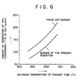
- Figure 6 shows the maximum temperature of the radiant tube versus the amount of generation of NOx to explain the effect of NOx reduction according to the present invention. It is obvious that NOx can be reduced by approximately 30% compared with a prior art radiant tube burner.
- the gas burner 1 is placed coaxially with the combustion tube 2.
- the divergent flame type nozzle 3a is mounted at the end of the burner 1.
- the primary air supply tube 5 joins the rear end of the combustion tube 5 to form an integral piece extending coaxially with the burner 1.
- the primary air supply tube 5 has four rectangular ports 6 evenly spaced over the entire periphery thereof.
- the primary air swirling vanes 10 having an angle within the range from 15 to 60° are secured on a retaining tube (not shown) at the end of said burner 1.
- the combustion tube 2 and the primary air supply tube 5 are coaxially housed in the radiant tube 12.
- the primary air supply tube and the radiant tube are closed by the end cover 14 through flanges respectively, whereas the gas burner 1 passes through the end cover 14 to extend rearward.
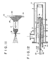
- a water spray nozzle 18 communicating with an additive water transfer tube 17 placed in said gas burner 1 is provided at the center of the divergent flame type nozzle 3a, and a number of gas injection ports 19 communicating with the gas connection 4 are provided around said nozzle 18 as shown in Figure 8. Further, an air supply connection 13 is connected to the rear section of the radiant tube 12. An atomized water generator 22 connected to a pressurized gas tube 20 and an additive water transfer tube 21 is fitted to the rear end of water transfer tube 17.
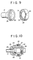
- the atomized water generator 22 consists of a disk 24 having a circular recess 23 and a conical hole 25 with its diameter gradually decreasing from that corresponding to said recess. Further, a cylinder 26 having the same diameter as that of said disk 24 is coaxially fitted to said disk so that they mate with each other, and they are then built in a housing 27. The disk 24 is surely pressed by a plug 28 and the cylinder 26 is connected to the additive water transfer tube 17. When the disk is fitted to the cylinder, an atomized water generating chamber 29 is formed.
- Grooves 30 and 31 for introducing the pressurized gas and the additive water and communicating with said recess 23 in the tangential direction thereof are provided on one plane perpendicular to the center axis at the end face of the disk 24 near the cylinder 26. These grooves 30, 31 are connected to the pressurized gas suply tube 20 and the additive water supply tube 21 respectively.
- the second embodiment of the present invention is a combination of the first embodiment and atomized water injection.
- the fuel gas supplied to the gas burner 1 through the connection 4 is ejected from the divergent flame type nozzle 3a into the combustion tube 2.
- the jetted fuel gas mixes with the primary air C, which flows through the inlet 6 and is swirled by the primary air swirling vanes 10 before being burnt in reduced primary combustion at the high heat load. Then, the primary combustion gas issues from the combustion tube 2 similarly to the first embodiment noted above.
- the secondary air C 2 throttled by the air damper 7 as shown in Figure 1 to be at a required ratio with respect to the primary air C is fed through the annular passage between the combustion tube 2 and the radiant tube 12, cooling said combustion tube 2, and then flows along the inside of the radiant tube 12.
- the atomized water is obtained by the atomized water generator 22, as shown in Figures 10 and 11, being injected from the water spray nozzle 18 located at the center of the divergent flame type nozzle 3a, thereby reducing the flame temperature to restrain the generation of NOx.
- bubbles of the atomized water are sharply expanded to blow up through injection due to the differential pressure across the bubbles and the combustion tube.
- the thickness of the bubble is very thin, i.e., 0.1 ⁇ m or above, the pieces of the blown-up bubbles are very fine. Therefore, the fine water particles will quickly absorb the latent heat from the flame, thereby greatly reducing the generation of NOx due to the lowered flame temperature.
- FIG. 12 and 13 refer to the corresponding parts which are the same as illustrated in Figures 7 and 8. However, it differs from the second embodiment in that the exhaust gas is ejected into the center of the fuel gas as atomizing medium while in the second embodiment water is used as atomizing medium.
- the mechanism of the radiant tube burner in the third embodiment of the present invention is similar to that of the second embodiment with the only difference that the nozzle is constituted as a divergent flame type nozzle 3b, it will not be further described here.
- Figure 14 shows a modification of the third embodiment of the present invention making use of an atomizing system due to low pressure fuel gas.
- the gas burner 1 is placed coaxially with the combustion tube 2.
- the divergent flame type nozzle 3c is provided at the front end of the burner 1.
- a water outflow nozzle 32 is provided at the center of the nozzle 3c.
- gas swirling vanes 33 having an angle within the range from 15 to 40°.
- the operating mechanism of the radiant tube burner of the modification of the third embodiment employing the atomizing system with low pressure fuel gas will be described in the following.
- the gas G introduced into the gas burner 1 from the gas connection 4 is fed in the direction shown by the arrow to be swirled at high speed by the gas swirling vanes 33, while the water W introduced into the additive water transfer tube 17 (See Figures 12 and 13) connected to an additive water connection port 36 is fed in the direction shown by an arrow to issue from the water outflow nozzle 32.
- the water discharged from the water outflow nozzle is atomized by the kinetic energy of the fuel gas.
- the atomized water and fuel gas are sufficiently mixed with each other and the effect of water addition is greatly enhanced.
- FIG 15 shows a further-modification of the third embodiment of the present invention in which the atomizing system uses low pressure exhaust gas.
- an exhaust gas introducing tube 34 for atomizing the water supplied from the water outflow nozzle 32 is placed at the center of the divergent flame type nozzle 3d.
- the additive water transfer tube 17 is placed at the center of the introducing tube 34.
- exhaust-gas-swirling vanes 35 having an angle within the range from 15 to 40°.
- the exhaust gas WG is swirled at high speed by the exhaust gas swirling vanes 35 to atomize the water W discharged from the water outflow nozzle 32.
- the atomized water is mixed with the fuel gas G, supplied from the divergent flame type nozzle 3d, by the high speed swirling flow of the exhaust gas. Therefore, the mixing of the exhaust gas and the fuel gas and that of the fuel gas and the atomized water occur rapidly to reduce the flame temperature by making the flame temperature uniform due to the combustion delay of the fuel gas and absorption of the latent heat by the atomized water, thereby greatly reducing the generation of NOx.
- the radiant tube burners including two modifications of the third embodiment noted above has two types of water atomizing system.
- One is using pressurized gas (air, vapor and inert gas) within the range from 2 to 6 kg/cm 2 and the other is using low pressure gas (fuel gas, exhaust gas or the like) in the range from 300 to 1,000 mm Hg.
- NOx reduction rate by adding water in the radiant tube burner according to these embodiments of the present invention is represented by the relation between the amount of additive water and the NOx reduction rate as shown in Figure 16.
- the amount of additive water is gradually increased to obtain higher NOx reduction rate (%).
- the radiant tube burner according to the present invention will give utmost effectiveness when used for a furnace in which direct exposure of workpieces to waste gas is not desirable, e.g. non- oxidation furnaces, heat treatment furnaces and the like utilizing atmospheric gas, and indirect heating systems in which workpieces and waste gas should not come in contact.
- Applicable fields will include those industries such as metal working industry, ceramics, glass industry, chemical industry, paper and fiber industry and food industry or the like.
Landscapes
- Engineering & Computer Science (AREA)
- Chemical & Material Sciences (AREA)
- Combustion & Propulsion (AREA)
- Mechanical Engineering (AREA)
- General Engineering & Computer Science (AREA)
- Gas Burners (AREA)
Claims (8)
Priority Applications (1)
| Application Number | Priority Date | Filing Date | Title |
|---|---|---|---|
| AT86906451T ATE56520T1 (de) | 1985-10-31 | 1986-10-30 | Strahlungsrohrbrenner. |
Applications Claiming Priority (8)
| Application Number | Priority Date | Filing Date | Title |
|---|---|---|---|
| JP24293085 | 1985-10-31 | ||
| JP242930/85 | 1985-10-31 | ||
| JP267348/85 | 1985-11-29 | ||
| JP26734885 | 1985-11-29 | ||
| JP23701686A JPS62190311A (ja) | 1985-10-31 | 1986-10-07 | ラジアントチユ−ブバ−ナ |
| JP237017/86 | 1986-10-07 | ||
| JP23701786A JPS62242711A (ja) | 1985-11-29 | 1986-10-07 | ラジアントチユ−ブバ−ナ |
| JP237016/86 | 1986-10-07 |
Publications (3)
| Publication Number | Publication Date |
|---|---|
| EP0243506A1 EP0243506A1 (de) | 1987-11-04 |
| EP0243506A4 EP0243506A4 (de) | 1989-01-24 |
| EP0243506B1 true EP0243506B1 (de) | 1990-09-12 |
Family
ID=27477683
Family Applications (1)
| Application Number | Title | Priority Date | Filing Date |
|---|---|---|---|
| EP86906451A Expired - Lifetime EP0243506B1 (de) | 1985-10-31 | 1986-10-30 | Strahlungsrohrbrenner |
Country Status (4)
| Country | Link |
|---|---|
| EP (1) | EP0243506B1 (de) |
| AU (1) | AU573109B2 (de) |
| DE (1) | DE3674198D1 (de) |
| WO (1) | WO1987002756A1 (de) |
Families Citing this family (10)
| Publication number | Priority date | Publication date | Assignee | Title |
|---|---|---|---|---|
| FR2656676B1 (fr) * | 1989-12-28 | 1994-07-01 | Inst Francais Du Petrole | Bruleur industriel a combustible liquide a faible emission d'oxyde d'azote, ledit bruleur generant plusieurs flammes elementaires et son utilisation. |
| US5228283A (en) * | 1990-05-01 | 1993-07-20 | General Electric Company | Method of reducing nox emissions in a gas turbine engine |
| US5146741A (en) * | 1990-09-14 | 1992-09-15 | Solar Turbines Incorporated | Gaseous fuel injector |
| DE4138434C1 (de) * | 1991-11-22 | 1992-12-03 | Aichelin Gmbh, 7015 Korntal-Muenchingen, De | |
| US5513981A (en) * | 1991-11-22 | 1996-05-07 | Aichelin Gmbh | Burner with variable volume combination chamber |
| FI101419B1 (fi) * | 1996-11-26 | 1998-06-15 | Teollisuuslaempoe Oy | Kaasujen polttolaite |
| IT1287521B1 (it) * | 1996-12-20 | 1998-08-06 | Ipeg Spa | Bruciatore intensivo |
| US6872070B2 (en) * | 2001-05-10 | 2005-03-29 | Hauck Manufacturing Company | U-tube diffusion flame burner assembly having unique flame stabilization |
| ITVE20110066A1 (it) * | 2011-10-06 | 2013-04-07 | Foinox S P A | Scambiatore di calore per apparecchi di cottura a gas. |
| ITVE20110067A1 (it) * | 2011-10-06 | 2013-04-07 | Foinox S P A | Scambiatore di calore per apparecchi di cottura a gas. |
Family Cites Families (11)
| Publication number | Priority date | Publication date | Assignee | Title |
|---|---|---|---|---|
| JPS5218929B2 (de) * | 1973-01-18 | 1977-05-25 | ||
| JPS5070929A (de) * | 1973-10-24 | 1975-06-12 | ||
| JPS5240451B2 (de) * | 1974-02-06 | 1977-10-12 | ||
| JPS5229007B2 (de) * | 1974-05-27 | 1977-07-29 | ||
| JPS5156028A (ja) * | 1974-11-12 | 1976-05-17 | Nippon Kokan Kk | Chitsusosankabutsuyokuseihoho |
| JPS5221036U (de) * | 1975-08-02 | 1977-02-15 | ||
| JPS5222132A (en) * | 1975-08-07 | 1977-02-19 | Daido Steel Co Ltd | Burner combustion method and apparatus with addition of water |
| JPS57166410A (en) * | 1981-04-03 | 1982-10-13 | Maruzen Eng Kk | Water injection combustion method and water injection combustion burner |
| JPS5942427U (ja) * | 1982-09-10 | 1984-03-19 | 東京瓦斯株式会社 | 二重管式輻射管 |
| GB8301274D0 (en) * | 1983-01-18 | 1983-02-16 | Wb Combustion Ltd | Single-ended recouperative radiant tube |
| JPS60218519A (ja) * | 1984-04-13 | 1985-11-01 | Nippon Nenshiyou Syst Kk | 混焼用バ−ナ装置 |
-
1986
- 1986-10-30 EP EP86906451A patent/EP0243506B1/de not_active Expired - Lifetime
- 1986-10-30 AU AU65940/86A patent/AU573109B2/en not_active Ceased
- 1986-10-30 WO PCT/JP1986/000550 patent/WO1987002756A1/ja not_active Ceased
- 1986-10-30 DE DE8686906451T patent/DE3674198D1/de not_active Expired - Lifetime
Also Published As
| Publication number | Publication date |
|---|---|
| EP0243506A1 (de) | 1987-11-04 |
| WO1987002756A1 (fr) | 1987-05-07 |
| EP0243506A4 (de) | 1989-01-24 |
| DE3674198D1 (de) | 1990-10-18 |
| AU6594086A (en) | 1987-05-19 |
| AU573109B2 (en) | 1988-05-26 |
Similar Documents
| Publication | Publication Date | Title |
|---|---|---|
| US4813867A (en) | Radiant tube burner | |
| EP0690264B1 (de) | Kohlenstaubbrenner | |
| CA2211769C (en) | Low emission swirl burner | |
| EP0529779B1 (de) | Brenner mit geringer NOx-Produktion | |
| US4815966A (en) | Burner for burning liquid or gaseous fuels | |
| EP0887589B1 (de) | Vorrichtung und verfahren zur verbrennung von brennstoff | |
| EP0248539B1 (de) | Zerstäuber und damit ausgerüsteter Kohle-Wasserschlamm-Heizkessel | |
| JPS63210508A (ja) | 超低NOx燃焼装置 | |
| US4412808A (en) | Dual fueled burner gun | |
| US4601428A (en) | Burner tip | |
| EP0243506B1 (de) | Strahlungsrohrbrenner | |
| US5388536A (en) | Low NOx burner | |
| US6145450A (en) | Burner assembly with air stabilizer vane | |
| US4105393A (en) | Fuel burners | |
| US5685706A (en) | V-jet atomizer | |
| JPH0252765B2 (de) | ||
| JPH06341611A (ja) | 燃焼からのNOx放出量を最小限に抑える方法およびバーナ | |
| CA1228796A (en) | Low pressure loss burner for coal-water slurry or fuel oil | |
| JPH08135920A (ja) | 微粉炭バーナ | |
| JP2001116214A (ja) | 三位置制御バーナ | |
| JPH0474603B2 (de) | ||
| KR910001837B1 (ko) | 레이디언트 튜브 버너 | |
| CA1286590C (en) | Radiant tube burner | |
| CA1282314C (en) | Radiant tube burner | |
| KR100246876B1 (ko) | 동시 또는 독립적으로 공급되는 2종 연료로 작동가능한 버너 |
Legal Events
| Date | Code | Title | Description |
|---|---|---|---|
| PUAI | Public reference made under article 153(3) epc to a published international application that has entered the european phase |
Free format text: ORIGINAL CODE: 0009012 |
|
| 17P | Request for examination filed |
Effective date: 19870616 |
|
| AK | Designated contracting states |
Kind code of ref document: A1 Designated state(s): AT BE CH DE FR GB IT LI LU NL SE |
|
| A4 | Supplementary search report drawn up and despatched |
Effective date: 19890124 |
|
| 17Q | First examination report despatched |
Effective date: 19890629 |
|
| GRAA | (expected) grant |
Free format text: ORIGINAL CODE: 0009210 |
|
| AK | Designated contracting states |
Kind code of ref document: B1 Designated state(s): AT BE CH DE FR GB IT LI LU NL SE |
|
| PG25 | Lapsed in a contracting state [announced via postgrant information from national office to epo] |
Ref country code: IT Free format text: LAPSE BECAUSE OF FAILURE TO SUBMIT A TRANSLATION OF THE DESCRIPTION OR TO PAY THE FEE WITHIN THE PRE;WARNING: LAPSES OF ITALIAN PATENTS WITH EFFECTIVE DATE BEFORE 2007 MAY HAVE OCCURRED AT ANY TIME BEFORE 2007. THE CORRECT EFFECTIVE DATE MAY BE DIFFERENT FROM THE ONE RECORDED.SCRIBED TIME-LIMIT Effective date: 19900912 Ref country code: LI Effective date: 19900912 Ref country code: SE Effective date: 19900912 Ref country code: AT Effective date: 19900912 Ref country code: CH Effective date: 19900912 Ref country code: NL Effective date: 19900912 |
|
| REF | Corresponds to: |
Ref document number: 56520 Country of ref document: AT Date of ref document: 19900915 Kind code of ref document: T |
|
| ET | Fr: translation filed | ||
| REF | Corresponds to: |
Ref document number: 3674198 Country of ref document: DE Date of ref document: 19901018 |
|
| PG25 | Lapsed in a contracting state [announced via postgrant information from national office to epo] |
Ref country code: LU Free format text: LAPSE BECAUSE OF NON-PAYMENT OF DUE FEES Effective date: 19901031 |
|
| REG | Reference to a national code |
Ref country code: CH Ref legal event code: PL |
|
| NLV1 | Nl: lapsed or annulled due to failure to fulfill the requirements of art. 29p and 29m of the patents act | ||
| PLBE | No opposition filed within time limit |
Free format text: ORIGINAL CODE: 0009261 |
|
| STAA | Information on the status of an ep patent application or granted ep patent |
Free format text: STATUS: NO OPPOSITION FILED WITHIN TIME LIMIT |
|
| 26N | No opposition filed | ||
| PGFP | Annual fee paid to national office [announced via postgrant information from national office to epo] |
Ref country code: GB Payment date: 19961018 Year of fee payment: 11 |
|
| PGFP | Annual fee paid to national office [announced via postgrant information from national office to epo] |
Ref country code: FR Payment date: 19961029 Year of fee payment: 11 |
|
| PGFP | Annual fee paid to national office [announced via postgrant information from national office to epo] |
Ref country code: BE Payment date: 19961118 Year of fee payment: 11 |
|
| PGFP | Annual fee paid to national office [announced via postgrant information from national office to epo] |
Ref country code: DE Payment date: 19961126 Year of fee payment: 11 |
|
| PG25 | Lapsed in a contracting state [announced via postgrant information from national office to epo] |
Ref country code: GB Free format text: LAPSE BECAUSE OF NON-PAYMENT OF DUE FEES Effective date: 19971030 |
|
| PG25 | Lapsed in a contracting state [announced via postgrant information from national office to epo] |
Ref country code: BE Free format text: LAPSE BECAUSE OF NON-PAYMENT OF DUE FEES Effective date: 19971031 Ref country code: FR Free format text: THE PATENT HAS BEEN ANNULLED BY A DECISION OF A NATIONAL AUTHORITY Effective date: 19971031 |
|
| BERE | Be: lapsed |
Owner name: NIHON NENSHO SYSTEM K.K. Effective date: 19971031 Owner name: KAWAZAKI SEITETSU K.K. Effective date: 19971031 Owner name: MITSUBISHI JUKOGYO K.K. Effective date: 19971031 |
|
| GBPC | Gb: european patent ceased through non-payment of renewal fee |
Effective date: 19971030 |
|
| PG25 | Lapsed in a contracting state [announced via postgrant information from national office to epo] |
Ref country code: DE Free format text: LAPSE BECAUSE OF NON-PAYMENT OF DUE FEES Effective date: 19980701 |
|
| REG | Reference to a national code |
Ref country code: FR Ref legal event code: ST |