EP0243339A1 - Nockenwelle - Google Patents
Nockenwelle Download PDFInfo
- Publication number
- EP0243339A1 EP0243339A1 EP87890041A EP87890041A EP0243339A1 EP 0243339 A1 EP0243339 A1 EP 0243339A1 EP 87890041 A EP87890041 A EP 87890041A EP 87890041 A EP87890041 A EP 87890041A EP 0243339 A1 EP0243339 A1 EP 0243339A1
- Authority
- EP
- European Patent Office
- Prior art keywords
- cam
- camshaft
- radius
- base circle
- tappet
- Prior art date
- Legal status (The legal status is an assumption and is not a legal conclusion. Google has not performed a legal analysis and makes no representation as to the accuracy of the status listed.)
- Granted
Links
Images

Classifications
-
- F—MECHANICAL ENGINEERING; LIGHTING; HEATING; WEAPONS; BLASTING
- F02—COMBUSTION ENGINES; HOT-GAS OR COMBUSTION-PRODUCT ENGINE PLANTS
- F02M—SUPPLYING COMBUSTION ENGINES IN GENERAL WITH COMBUSTIBLE MIXTURES OR CONSTITUENTS THEREOF
- F02M59/00—Pumps specially adapted for fuel-injection and not provided for in groups F02M39/00 -F02M57/00, e.g. rotary cylinder-block type of pumps
- F02M59/02—Pumps specially adapted for fuel-injection and not provided for in groups F02M39/00 -F02M57/00, e.g. rotary cylinder-block type of pumps of reciprocating-piston or reciprocating-cylinder type
- F02M59/10—Pumps specially adapted for fuel-injection and not provided for in groups F02M39/00 -F02M57/00, e.g. rotary cylinder-block type of pumps of reciprocating-piston or reciprocating-cylinder type characterised by the piston-drive
- F02M59/102—Mechanical drive, e.g. tappets or cams
-
- F—MECHANICAL ENGINEERING; LIGHTING; HEATING; WEAPONS; BLASTING
- F01—MACHINES OR ENGINES IN GENERAL; ENGINE PLANTS IN GENERAL; STEAM ENGINES
- F01L—CYCLICALLY OPERATING VALVES FOR MACHINES OR ENGINES
- F01L1/00—Valve-gear or valve arrangements, e.g. lift-valve gear
- F01L1/02—Valve drive
- F01L1/04—Valve drive by means of cams, camshafts, cam discs, eccentrics or the like
- F01L1/08—Shape of cams
-
- F—MECHANICAL ENGINEERING; LIGHTING; HEATING; WEAPONS; BLASTING
- F16—ENGINEERING ELEMENTS AND UNITS; GENERAL MEASURES FOR PRODUCING AND MAINTAINING EFFECTIVE FUNCTIONING OF MACHINES OR INSTALLATIONS; THERMAL INSULATION IN GENERAL
- F16H—GEARING
- F16H53/00—Cams or cam-followers, e.g. rollers for gearing mechanisms
- F16H53/02—Single-track cams for single-revolution cycles; Camshafts with such cams
Definitions
- the invention relates to a camshaft with at least one cam which, for controlling a tappet, preferably provided with a roller or the like, has a cam starting from a cam base circle, lifting the tappet into its highest position and one arranged in the direction of rotation of the camshaft after it and having a portion lowering the tappet and ending at the cam base circle.
- camshafts are often used to drive pump pistons of fuel injection pumps for internal combustion engines, e.g. Diesel engines used.
- the geometrical shape of a cam for the roller tappet drive of an injection pump is either built up from different geometrical lines with a simple law of formation or it is determined from an assumed course of elevation and thus also speed and acceleration, which takes the geometrical boundary conditions into account, the geometrical shape of the cam and subsequently based on the manufacturing data of the cam.
- the main characteristics of the injection cam are the radii of the base circle and tip circle and a certain range.
- the radius of the tappet roller is an important influencing variable.
- the difference between the base circle and tip circle radius represents the cam stroke, which is a measure of the possible delivery quantity of the injection pump is.
- the base circle radius of the cam is usually somewhat larger or the same size as the radius of the sections of the camshaft between two cams.
- the base circle diameter is decisive for the torsional and bending stiffness of the camshaft, which are of great importance for the exact realization of the desired fuel delivery curve at the high pump chamber pressures that occur.
- the first area of the cam contour lying in front in the direction of rotation of the camshaft, which directly adjoins the base circle, is an arc with a large positive radius compared to the radius of the cam base circle, a tangent or an arc with a large negative radius, the center of which is outside the cross-sectional area enclosed by the cam base circle.
- Areas with a variable radius of curvature can also be realized, e.g. the survey should obey a certain educational law.
- diesel injection pumps shows that, on the one hand, the greatest possible stroke is required in order to achieve large delivery volumes and speeds, and on the other hand, a large cam base circle is expedient in order to be able to implement a drive train that is as resistant to bending and torsion as possible.
- a large base circle radius of the camshaft also results in a large tip circle radius and thus large pumps Dimensions.
- the aim of the invention is to propose a camshaft of the type mentioned at the outset, which makes it possible to increase the achievable conveying speed and stroke when controlling pumps with the same head diameter of the cams, but the strength of the camshaft is to be essentially retained .
- the contour of the cam has a positive, possibly different, radius which is smaller than the radius of the cam base circle.
- the area of the contour of the cam with a smaller radius than the cam base circle is adjoined by an area with a radius, which may also change to positive, which is larger than that of the cam base circle.
- Both a curvature with a negative radius, in which the center lies outside the cross-sectional area enclosed by the cam base circle and on the same profile side as the roller center, and also with an infinite length, can be provided. with an infinitely large radius.
- the area of the contour of the cam with a smaller radius than the cam base circle can be directly adjoined by an area with a rectilinear contour or an area with a possibly changing radius, the center of curvature (e) of which lies on the same profile side as the center of the roller (lie) and whose absolute value is larger than the radius of the tappet roller.
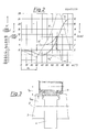
- FIG. 1 shows the cam outline NU of a cam 4, which is used to drive a roller tappet and, subsequently, a pump piston, not shown, of a diesel injection pump.
- R R denotes the roller radius of the tappet roller 2 and MB represents the center path of the tappet roller rotating around the cam profile. The consideration of the stationary cam and the roller rotating with the camshaft speed has proven to be advantageous.
- the differentiation of the survey value h according to the cam rotation angle ⁇ provides the related speed:
- the two differentiation of the elevation according to the cam angle provides the related acceleration: From Figure 1 it can be seen that the point at the cam base circle GK adjoining area of the cam outline has a smaller radius r 1 than the cam base circle.
- the directional angle ⁇ 1 of the path tangent to the center path MB is negative and the speed and acceleration act in the first region in the negative direction, ie in the direction of a further approximation to the axis of rotation Z of the camshaft 3.
- a region with a constant radius of curvature such with a variable radius of curvature in the initial region of the region of the cam contour lifting the tappet or its roller 5 and thus in the region of the beginning of the movement of the pump piston, for example by specifying an acceleration curve according to a specific law. It is essential that the curvature dius in this first area is smaller than the radius of the cam base circle and thus initially the plunger and thus the pump piston are lowered from their originally lowest position.
- a region is provided which causes a rapid increase in the deflection and the speed in relation to the angle of rotation, for example by adding a tangent or an arc with a large positive or with a negative radius.
- an arc with a large negative radius r 2 is applied, which creates a hollow cam. The arc extends from point 4 to cam 4 to the point and causes a lowering in the beginning, but then a rapid lifting of the roller tappet or roller 5.
- Figure 2 shows that at angle ⁇ 1, at which the transition from radius of curvature r1, which is positive but smaller than the radius r G of the cam base circle to radius r2 takes place, the related speed h ⁇ has reached its lowest value and then increases again. Where the speed h ⁇ intersects the abscissa, the lowest point of the elevation line h (FIG. 2) can be seen.
- the cam shape has its point closest to the center, the corresponding contact point BK has the radius r min .
- the upward movement of the roller tappet 5, which now begins, can take place according to the usual laws, for example by specifying certain profile geometries or educational laws for the survey curve.
- Figure 3 shows the cam 4 together with the roller 5 in longitudinal section in the area of the greatest approach of the roller 5 to the axis of rotation Z of the camshaft 3. It can be seen that in this area only a very slight weakening of the cross section of the camshaft occurs.
- the area having a positive but smaller radius than the cam base circle can be followed by an arcuate area, the radius of which is equal to the minimum radius r min .
Landscapes
- Engineering & Computer Science (AREA)
- General Engineering & Computer Science (AREA)
- Mechanical Engineering (AREA)
- Chemical & Material Sciences (AREA)
- Combustion & Propulsion (AREA)
- Fuel-Injection Apparatus (AREA)
- Valve-Gear Or Valve Arrangements (AREA)
Abstract
Description
- Die Erfindung bezieht sich auf eine Nockenwelle mit mindestens einer Nocke, die zur Steuerung eines - vorzugsweise mit einer Rolle od. dgl. versehenen - Stößels einen von einem Nockengrundkreis ausgehenden, den Stößel in seine höchste Lage hebenden und einen in Drehrichtung der Nockenwelle nach diesem angeordneten und am Nockengrundkreis endenden, den Stößel absenkenden Abschnitt aufweist.
- Derartige Nockenwellen werden häufig für den Antrieb von Pumpenkolben von Kraftstoff-Einspritzpumpen für Brennkraftmaschinen, wie z.B. Dieselmotoren verwendet.
- Die geometrische Form eines Nockens für den Rollenstößelantrieb einer Einspritzpumpe wird entweder aus verschiedenen geometrischen Linienzügen mit einfachem Bildungsgesetz aufgebaut oder es wird aus einem angenommenen Verlauf von Erhebung und damit auch Geschwindigkeit und Beschleunigung, der die als geometrischen Randbedingungen berücksichtigt, die geometrische Form des Nockens ermittelt und in weiterer Folge den Herstelldaten des Nockens zugrundegelegt. Der Einspritznocken weist als wesentliche Kenndaten die Radien von Grundkreis und Kopfkreis und eine bestimmte Tragbreite auf. Dazu kommt noch als wesentliche Einflußgröße der Radius der Stößelrolle. Bei bekannten Nockenwellen stellt die Differenz zwischen Grundkreis- und Kopfkreisradius den Nockenhub dar, welcher ein Maß für die mögliche Fördermenge der Einspritz pumpe ist. Der Grundkreisradius des Nockens ist meist etwas größer oder gleich groß wie der Radius der Abschnitte der Nockenwelle zwischen zwei Nocken. Der Grundkreisdurchmesser ist maßgeblich für die Torsions- und Biegesteifigkeit der Nockenwelle, welche bei den hohen auftretenden Pumpenraumdrücken von großer Bedeutung für die exakte Verwirklichung des gewünschten Kraftstoff-Förderverlaufes sind.
- Bei bekannten Nockenwellen ist als erster in Drehrichtung der Nockenwelle vorne liegender Bereich der Nockenkontur, der unmittelbar an den Grundkreis anschließt, ein Kreisbogen mit gegenüber dem Radius des Nockengrundkreises großem positivem Radius, eine Tangente oder ein Kreisbogen mit großem negativem Radius vorgesehen, dessen Mittelpunkt außerhalb der vom Nockengrundkreis umschlossenen Querschnittsfläche liegt. Dabei können auch Bereiche mit veränderlichem Krümmungsradius verwirklicht werden, wenn z.B. die Erhebung einem bestimmten Bildungsgesetz gehorchen soll.
- Durch diesen ersten Abschnitt wird ein rascher Anstieg der Geschwindigkeit erreicht. Der Richtungswinkel der Rollenmittelpunktsbahn zur Normalen auf die Verbindungslinie Nockenzentrum/Rollenzentrum ist dabei stets positiv, d.h. die Geschwindigkeit des Rollenstößels und Pumpenkolbens ist ebenfalls positiv. Es besteht sogar ein gewisses Vorurteil der Fachwelt gegen eine andere Ausbildung. So wird in der AT-PS 2l9 350 festgestellt, daß ein anderer Verlauf sinnlos wäre.
- Bei der Konstruktion von Dieseleinspritzpumpen zeigt es sich, daß einerseits ein möglichst großer Hub erforderlich ist, um große Fördermengen und -geschwindigkeiten zu erzielen, andererseits ein großer Nockengrundkreis zweckmäßig ist, um einen möglichst biege- und verwindungssteifen Antriebsstrang verwirklichen zu können. Ein großer Grundkreisradius der Nockenwelle bewirkt aber auch einen großen Kopfkreisradius und damit große Pumpen abmessungen.
- Ziel der Erfindung ist es, eine Nockenwelle der eingangs erwähnten Art vorzuschlagen, die es ermöglicht, bei einer Ansteuerung von Pumpen bei gleichem Kopfdurchmesser der Nocken eine Erhöhung der erreichbaren Fördergeschwindigkeit und des Hubes zu erreichen, wobei aber die Festigkeit der Nockenwelle im wesentlichen erhalten bleiben soll.
- Erfindungsgemäß wird dies dadurch erreicht, daß in dem an den Nockengrundkreis unmittelbar anschließenden, in Drehrichtung der Nockenwelle vorne liegenden Bereich die Kontur der Nocke einen positiven, sich gegebenenfalls andernden Radius aufweist, der kleiner als der Radius des Nockengrundkreises ist. Durch diese Maßnahmen wird eine Vergrößerung des Hubes und damit der Fördermenge, z.B. einer Dieseleinspritzpumpe, ohne eine Vergrößerung des Kopfkreisradius und ohne einer Verkleinerung des Grundkreisradius des Nockens möglich. Aufgrund des an den Nockengrundkreis anschließenden Konturbereichs mit kleinem Radius kommt es vorerst zu einer Absenkung des Rollenstößels um einen Betrag, der vorzugsweise 5 bis 20 % des Hubes betragen kann. Damit wird eine Vergrößerung des Hubes des Stößels und damit der Fördermenge der daran an geschlossenen Pumpe erreicht, wobei nur eine sehr geringe Schwächung der Nockenwelle in Kauf genommen werden muß.
- Nach einem weiteren Merkmal der Erfindung ist vorgesehen, daß an den Bereich der Kontur der Nocke mit einem kleineren Radius als der Nockengrundkreis ein Bereich mit einem, sich gegebenenfalls auch ins Positive ändernden Radius anschließt, der größer als jener des Nockengrundkreises ist. Dabei kann sowohl eine Krümmung mit negativem Radius, bei dem der Mittelpunkt außerhalb der vom Nockengrundkreis umschlossenen Querschnittsfläche und auf der gleichen Profilseite wie das Rollenzentrum liegt, als auch mit unendlicher Länge entspricht, vorgesehen werden. mit unendlich großem Radius darstellt, vorgesehen werden. Durch eine solche Ausbildung des an den Anfangsbereich des den Stößel auf seine höchste Erhebung anhebenden Bereichs der Nockenkontur anschließenden Abschnittes kommt es zu einer Beschleunigungsumkehr und nach einem gewissen Drehwinkel der Nockenwelle auch zur Geschwindigkeitsund Bewegungsumkehr. Durch diesen Ausholeffekt kann eine wesentlich höhere Kolbengeschwindigkeit erzielt werden, ohne daß der Nockenwellenkörper nennenswert geschwächt wird. Durch die nur örtlich notwendige Ausarbeitung des Grundkreises entstehen keine wesentlichen Verminderungen der Nockenwellensteifigkeit.
- Das relativ weiche Durchfahren des unteren Totpunktes der Kolbenbewegung gibt anderseits genügend Zeit für das Auffüllen des Pumpenraumes mit Kraftstoff über die Saugbohrung im Pumpenzylinder.
- Im Rahmen der Erfindung können an den Bereich der Kontur der Nocke mit einem kleineren Radius als der Nockengrundkreis unmittelbar ein Bereich mit einem geradlinigen Konturverlauf oder ein Bereich mit einem sich gegebenenfalls ändernden Radius anschließen, dessen Krümmungsmittelpunkt(e) auf der gleichen Profilseite wie der Rollenmittelpunkt liegt (liegen) und dessen Absolutwert größer ist als der Radius der Stößelrolle.
- Die Erfindung wird nun anhand der Zeichnung näher erläutert. Dabei zeigen
- Figur l einen Nocken gemäß der Erfindung mit der Mittelpunktsbahn der darauf ablaufenden Rolle,
- Figur 2 die Diagramme von Erhebung, bezogener Geschwindigkeit und bezogener Beschleunigung, aufgetragen über dem Nockenwinkel und
- Figur 3 den Längsschnitt durch eine Einspritzpumpe, wobei sich der Rollenstößel gerade in der tiefsten Stellung befindet.
- In Figur l ist der Nockenumriß NU eines Nockens 4 dargestellt, der zum Antrieb eines Rollenstößels und in weiterer Folge eines nicht dargestellten Pumpenkolbens einer Dieseleinspritzpumpe dient. Mit rR ist der Rollenradius der Stößelrolle 2 bezeichnet und MB stellt die Mittelpunktsbahn der um das Nockenprofil rotierenden Stößelrolle dar. Die Betrachtungsweise des stillstehenden Nockens und der mit der Nockenwellendrehzahl um diesen rotierenden Rolle hat sich als vorteilhaft erwiesen. Der Wert der Erhebung h bei einem Drehwinkel α ergibt sich dabei aus dem Mittelpunktsabstand von Rollen- und Nockenzentrum, vermindert um die Radien des Nockengrundkreises rG und der Rolle rR:
h = H - rG - rR
Die Differentiation des Erhebungswertes h nach dem Nockendrehwinkel α liefert die bezogene Geschwindigkeit:
 anschließende Bereich des Nockenumrisses einen kleineren Radius r₁, aufweist als der Nockengrundkreis. Dadurch wird der Richtungswinkel ε₁ der Bahntangente an die Mittelpunktsbahn MB negativ und die Geschwindigkeit und Beschleunigung wirken im ersten Bereich in negativer Richtung, d.h. in Richtung einer weiteren Annäherung an die Drehachse Z der Nockenwelle 3. Natürlich kann statt eines Bereiches mit konstantem Krümmungsradius auch ein solcher mit veränderlichem Krümmungsradius im Anfangsbereich des den Stößel bzw. dessen Rolle 5 hebenden Bereichs der Nockenkontur und damit im Bereich des Bewegungsbeginns des Pumpenkolbens angesetzt werden, beispielsweise durch Festlegung eines Beschleunigungsverlaufes nach einer bestimmten Gesetzmäßigkeit. Wesentlich ist dabei, daß der Krümmungsra dius in diesem ersten Bereich kleiner ist als der Radius des Nockengrundkreises und damit vorerst ein Absenken des Stößels und damit des Pumpenkolbens aus seiner ursprünglich tiefsten Stellung erfolgt. Dabei ist bei der Nockenauslegung darauf zu achten, daß die Beschleunigung im ersten Bereich in keinem Punkt betragsmäßig so groß wird, daß sie in Zusammenwirkung mit der aktuellen Kraft der Pumpenfeder ein Abheben der Rolle 5 vom Nocken 4 bei der höchsten Drehzahl der Nockenwelle 3 verursachen könnte, d.h. die Beschleunigung muß stets im Betrag kleiner sein als jene Beschleunigung h
 (Figur 2), die die Stößelfeder der gemeinsamen Masse von Pumpenkolben, Rollenstößel und anteiliger Feder bei der jeweiligen Erhebung mitzuteilen vermag.
- Anschließend an den ersten Bereich der Nockenkontur von Punktbis zum
 , bzw. von O bis auf l auf der Mittel punktsbahn MB ist ein Bereich vorgesehen, der einen raschen Anstieg der Auslenkung und der Geschwindigkeit bezogen auf den Drehwinkel bewirkt, beispielsweise durch Anfügen einer Tangente oder eines Bogens mit großem positivem oder mit negativem Radius. Bei der Ausführungsform nach der Figur l ist ein Bogen mit großem negativem Radius r₂ angewendet, womit ein Hohlnocken entsteht. Der Bogen reicht auf dem Nocken 4 von Punkt
 bis zum Punkt
 und bewirkt im Anfang noch ein Absenken, dann aber ein rasches Anheben des Rollenstößels bzw. der Rolle 5. Figur 2 zeigt, daß beim Winkel α₁, bei welchem der Übergang von Krümmungsradius r₁, der positiv aber kleiner als der Radius rG des Nockengrundkreises ist zum Radius r₂ stattfindet, die bezogene Geschwindigkeit hʹ ihren niedrigsten Wert erreicht hat und dann wieder ansteigt. Dort wo die Geschwindigkeit hʹ die Abszisse schneidet, ist der tiefste Punkt der Erhebungslinie h (Figur 2) zu erkennen. Die Nockenform weist dort ihren zentrumsnächsten Punkt auf, der entsprechende Berührungspunkte BK weist den Radius rmin auf. Die nun einsetzende Aufwärtsbewegung des Rollenstößels 5 kann nach den üblichen Gesetzmäßigkeiten erfolgen, beispielsweise durch Vorgabe bestimmter Profilgeometrien oder Bildungsgesetze für die Erhebungskurve.
- Die dargestellte Vergrößerung des Gesamthubes ohne eine bedeutsame Schwächung des Nockenwellengrundkörpers ermöglicht eine gleichlaufende Erhöhung der Förderge schwindigkeit und der Förderrate, d.i. die pro Winkeleinheit geförderte Kraftstoffmenge. Damit kann bei unverändertem Bauraum einer Einspritzpumpe eine wesentlich höhere Einspritzmenge gefördert werden.
- Figur 3 zeigt die Nocke 4 samt der Rolle 5 im Längsschnitt im Bereich der größten Annäherung der Rolle 5 an die Drehachse Z der Nockenwelle 3. Es ist zu ersehen, daß in diesem Bereich nur eine sehr geringe Schwächung des Querschnittes der Nockenwelle eintritt.
- Grundsätzlich ist zu bemerken, daß sich an den einen positiven aber kleineren Radius als der Nockengrundkreis aufweisenden Bereich ein bogenförmiger Bereich, dessen Radius gleich dem minimalen Radius rmin ist, anschließen kann.
Claims (5)
Applications Claiming Priority (2)
| Application Number | Priority Date | Filing Date | Title |
|---|---|---|---|
| AT105386 | 1986-04-21 | ||
| AT1053/86 | 1986-04-21 |
Publications (2)
| Publication Number | Publication Date |
|---|---|
| EP0243339A1 true EP0243339A1 (de) | 1987-10-28 |
| EP0243339B1 EP0243339B1 (de) | 1992-06-03 |
Family
ID=3505564
Family Applications (1)
| Application Number | Title | Priority Date | Filing Date |
|---|---|---|---|
| EP87890041A Expired - Lifetime EP0243339B1 (de) | 1986-04-21 | 1987-03-04 | Nockenwelle |
Country Status (3)
| Country | Link |
|---|---|
| EP (1) | EP0243339B1 (de) |
| AT (1) | ATE76936T1 (de) |
| DE (1) | DE3779486D1 (de) |
Cited By (8)
| Publication number | Priority date | Publication date | Assignee | Title |
|---|---|---|---|---|
| EP0375944A3 (en) * | 1988-11-24 | 1990-10-10 | Nippondenso Co., Ltd. | Variable-discharge high pressure pump |
| EP0453227A1 (de) * | 1990-04-20 | 1991-10-23 | Zexel Corporation | Kraftstoffeinspritzpumpe |
| US5230613A (en) * | 1990-07-16 | 1993-07-27 | Diesel Technology Company | Common rail fuel injection system |
| EP0574867A1 (de) * | 1992-06-19 | 1993-12-22 | CENTRO RICERCHE FIAT Società Consortile per Azioni | Hubventilsteuerungsvorrichtung einer Brennkraftmaschine |
| EP0718488A1 (de) * | 1994-12-21 | 1996-06-26 | Toyota Jidosha Kabushiki Kaisha | Brennstoffeinspritzpumpe für einen Dieselmotor |
| WO2010130497A1 (de) * | 2009-05-13 | 2010-11-18 | Robert Bosch Gmbh | Hochdruckpumpe |
| WO2013131662A1 (de) * | 2012-03-05 | 2013-09-12 | Robert Bosch Gmbh | Kolbenpumpe |
| CN106368754A (zh) * | 2016-08-29 | 2017-02-01 | 潍柴动力股份有限公司 | 一种进气门装置、配气系统及配气相位切换方法 |
Citations (4)
| Publication number | Priority date | Publication date | Assignee | Title |
|---|---|---|---|---|
| GB299001A (en) * | 1927-10-19 | 1928-10-19 | Marc Birkigt | Improvements in or relating to cams |
| US1849490A (en) * | 1927-06-24 | 1932-03-15 | Junkers Hugo | Fuel feed pump and method of operating same |
| US3259077A (en) * | 1964-10-26 | 1966-07-05 | Dow Chemical Co | Multi-syringe-type pump |
| DE3236800A1 (de) * | 1982-10-05 | 1984-04-05 | Mtu Motoren- Und Turbinen-Union Friedrichshafen Gmbh, 7990 Friedrichshafen | Nockenwelle |
-
1987
- 1987-03-04 AT AT87890041T patent/ATE76936T1/de not_active IP Right Cessation
- 1987-03-04 EP EP87890041A patent/EP0243339B1/de not_active Expired - Lifetime
- 1987-03-04 DE DE8787890041T patent/DE3779486D1/de not_active Expired - Lifetime
Patent Citations (4)
| Publication number | Priority date | Publication date | Assignee | Title |
|---|---|---|---|---|
| US1849490A (en) * | 1927-06-24 | 1932-03-15 | Junkers Hugo | Fuel feed pump and method of operating same |
| GB299001A (en) * | 1927-10-19 | 1928-10-19 | Marc Birkigt | Improvements in or relating to cams |
| US3259077A (en) * | 1964-10-26 | 1966-07-05 | Dow Chemical Co | Multi-syringe-type pump |
| DE3236800A1 (de) * | 1982-10-05 | 1984-04-05 | Mtu Motoren- Und Turbinen-Union Friedrichshafen Gmbh, 7990 Friedrichshafen | Nockenwelle |
Cited By (17)
| Publication number | Priority date | Publication date | Assignee | Title |
|---|---|---|---|---|
| EP0375944A3 (en) * | 1988-11-24 | 1990-10-10 | Nippondenso Co., Ltd. | Variable-discharge high pressure pump |
| US5058553A (en) * | 1988-11-24 | 1991-10-22 | Nippondenso Co., Ltd. | Variable-discharge high pressure pump |
| EP0481964A3 (en) * | 1988-11-24 | 1992-07-08 | Nippondenso Co., Ltd. | Variable-discharge high pressure pump |
| EP0453227A1 (de) * | 1990-04-20 | 1991-10-23 | Zexel Corporation | Kraftstoffeinspritzpumpe |
| US5165851A (en) * | 1990-04-20 | 1992-11-24 | Zexel Corporation | Fuel injection pump |
| US5230613A (en) * | 1990-07-16 | 1993-07-27 | Diesel Technology Company | Common rail fuel injection system |
| EP0574867A1 (de) * | 1992-06-19 | 1993-12-22 | CENTRO RICERCHE FIAT Società Consortile per Azioni | Hubventilsteuerungsvorrichtung einer Brennkraftmaschine |
| US5309872A (en) * | 1992-06-19 | 1994-05-10 | Centro Ricerche Fiat Societa' Consortile Per Azioni | Device for operating a valve in an internal combustion engine |
| EP0718488A1 (de) * | 1994-12-21 | 1996-06-26 | Toyota Jidosha Kabushiki Kaisha | Brennstoffeinspritzpumpe für einen Dieselmotor |
| WO2010130497A1 (de) * | 2009-05-13 | 2010-11-18 | Robert Bosch Gmbh | Hochdruckpumpe |
| CN102422011A (zh) * | 2009-05-13 | 2012-04-18 | 罗伯特·博世有限公司 | 高压泵 |
| RU2554377C2 (ru) * | 2009-05-13 | 2015-06-27 | Роберт Бош Гмбх | Насос высокого давления |
| WO2013131662A1 (de) * | 2012-03-05 | 2013-09-12 | Robert Bosch Gmbh | Kolbenpumpe |
| CN104145114A (zh) * | 2012-03-05 | 2014-11-12 | 罗伯特·博世有限公司 | 活塞泵 |
| CN104145114B (zh) * | 2012-03-05 | 2017-07-28 | 罗伯特·博世有限公司 | 活塞泵 |
| CN106368754A (zh) * | 2016-08-29 | 2017-02-01 | 潍柴动力股份有限公司 | 一种进气门装置、配气系统及配气相位切换方法 |
| CN106368754B (zh) * | 2016-08-29 | 2019-01-15 | 潍柴动力股份有限公司 | 一种进气门装置、配气系统及配气相位切换方法 |
Also Published As
| Publication number | Publication date |
|---|---|
| DE3779486D1 (de) | 1992-07-09 |
| ATE76936T1 (de) | 1992-06-15 |
| EP0243339B1 (de) | 1992-06-03 |
Similar Documents
| Publication | Publication Date | Title |
|---|---|---|
| EP0261427B1 (de) | Zweirohr-Stossdämpfer | |
| DE69107687T2 (de) | Steuervorrichtung mit Nockenwelle und Kraftübertragungsmittel mit Rolle. | |
| DE2712450C2 (de) | Pumpenkolbenantrieb für eine Kraftstoffeinspritzpumpe für Brennkraftmaschinen | |
| EP0909883B1 (de) | Anordnung und Verfahren zur Ventilsteuerung einer umsteuerbaren Dieselbrennkraftmaschine | |
| EP1521929B1 (de) | Kolben für einen verbrennungsmotor | |
| DE10252074A1 (de) | Strömungsmengensteuerungsvorrichtung | |
| WO1987006318A1 (fr) | Soupape de non-retour | |
| EP1234106B1 (de) | Rollenstössel | |
| EP0402623B1 (de) | Kolben für Axialkolbenmaschinen | |
| EP0243339B1 (de) | Nockenwelle | |
| DE3914486A1 (de) | Verfahren zur herstellung einer ventilnadel und ventilnadel | |
| DE3406570A1 (de) | Elektromagnet/ventil-anordnung | |
| DE19653459A1 (de) | Stößel für einen Ventiltrieb einer Brennkraftmaschine | |
| DE102004002487A1 (de) | Rollenstößel | |
| DE102005047234A1 (de) | Rollenstößel | |
| EP1167737A2 (de) | Pleuelstange | |
| DE4118555A1 (de) | Foerderbeginnverstelleinrichtung einer kraftstoffeinspritzpumpe | |
| DE4019072A1 (de) | Federsystem | |
| DE102018124353A1 (de) | Verstellvorrichtung für eine Axialkolbenmaschine | |
| EP0797726B1 (de) | Ventiltrieb einer brennkraftmaschine | |
| DE102016202430A1 (de) | Rückschlagventil und Steuersystem | |
| DE19618253C1 (de) | Nocken einer Nockenwelle zur Steuerung eines Ventils in Hubkolben-Brennkraftmaschinen | |
| DE2947699A1 (de) | Kurbelwelle mit symmetrischer kroepfung | |
| WO2006119730A2 (de) | Verfahren und vorrichtung zur fertigung eines dreidimensionalen nockens und dreidimensionaler nocken, insbesondere zur variablen betätigung von hubventilen in brennkraftmaschinen | |
| DE102004025532A1 (de) | Tassenstößel eines Ventiltriebs einer Brennkraftmaschine |
Legal Events
| Date | Code | Title | Description |
|---|---|---|---|
| PUAI | Public reference made under article 153(3) epc to a published international application that has entered the european phase |
Free format text: ORIGINAL CODE: 0009012 |
|
| AK | Designated contracting states |
Kind code of ref document: A1 Designated state(s): AT DE GB |
|
| GBC | Gb: translation of claims filed (gb section 78(7)/1977) | ||
| 17P | Request for examination filed |
Effective date: 19871126 |
|
| 17Q | First examination report despatched |
Effective date: 19880518 |
|
| GRAA | (expected) grant |
Free format text: ORIGINAL CODE: 0009210 |
|
| AK | Designated contracting states |
Kind code of ref document: B1 Designated state(s): AT DE GB |
|
| REF | Corresponds to: |
Ref document number: 76936 Country of ref document: AT Date of ref document: 19920615 Kind code of ref document: T |
|
| GBT | Gb: translation of ep patent filed (gb section 77(6)(a)/1977) | ||
| REF | Corresponds to: |
Ref document number: 3779486 Country of ref document: DE Date of ref document: 19920709 |
|
| PLBE | No opposition filed within time limit |
Free format text: ORIGINAL CODE: 0009261 |
|
| STAA | Information on the status of an ep patent application or granted ep patent |
Free format text: STATUS: NO OPPOSITION FILED WITHIN TIME LIMIT |
|
| 26N | No opposition filed | ||
| REG | Reference to a national code |
Ref country code: GB Ref legal event code: IF02 |
|
| PGFP | Annual fee paid to national office [announced via postgrant information from national office to epo] |
Ref country code: GB Payment date: 20040310 Year of fee payment: 18 |
|
| PGFP | Annual fee paid to national office [announced via postgrant information from national office to epo] |
Ref country code: AT Payment date: 20040325 Year of fee payment: 18 |
|
| PGFP | Annual fee paid to national office [announced via postgrant information from national office to epo] |
Ref country code: DE Payment date: 20040406 Year of fee payment: 18 |
|
| PG25 | Lapsed in a contracting state [announced via postgrant information from national office to epo] |
Ref country code: GB Free format text: LAPSE BECAUSE OF NON-PAYMENT OF DUE FEES Effective date: 20050304 Ref country code: AT Free format text: LAPSE BECAUSE OF NON-PAYMENT OF DUE FEES Effective date: 20050304 |
|
| PG25 | Lapsed in a contracting state [announced via postgrant information from national office to epo] |
Ref country code: DE Free format text: LAPSE BECAUSE OF NON-PAYMENT OF DUE FEES Effective date: 20051001 |
|
| GBPC | Gb: european patent ceased through non-payment of renewal fee |
Effective date: 20050304 |