EP0243239A2 - Anlage zur Übertragung der Wärme zwischen einer Flüssigkeit und einem Organ zum Abkühlen oder zum Erwärmen durch Herabsetzen des Drucks der Flüssigkeit in Bezug auf den atmosphärischen Druck - Google Patents
Anlage zur Übertragung der Wärme zwischen einer Flüssigkeit und einem Organ zum Abkühlen oder zum Erwärmen durch Herabsetzen des Drucks der Flüssigkeit in Bezug auf den atmosphärischen Druck Download PDFInfo
- Publication number
- EP0243239A2 EP0243239A2 EP87400838A EP87400838A EP0243239A2 EP 0243239 A2 EP0243239 A2 EP 0243239A2 EP 87400838 A EP87400838 A EP 87400838A EP 87400838 A EP87400838 A EP 87400838A EP 0243239 A2 EP0243239 A2 EP 0243239A2
- Authority
- EP
- European Patent Office
- Prior art keywords
- fluid
- heated
- cooled
- installation
- installation according
- Prior art date
- Legal status (The legal status is an assumption and is not a legal conclusion. Google has not performed a legal analysis and makes no representation as to the accuracy of the status listed.)
- Granted
Links
- 238000009434 installation Methods 0.000 title claims abstract description 28
- 239000012530 fluid Substances 0.000 title claims abstract description 26
- 210000000056 organ Anatomy 0.000 title claims description 4
- 238000000034 method Methods 0.000 claims abstract description 8
- XLYOFNOQVPJJNP-UHFFFAOYSA-N water Substances O XLYOFNOQVPJJNP-UHFFFAOYSA-N 0.000 claims description 6
- 230000000630 rising effect Effects 0.000 claims description 5
- 238000001816 cooling Methods 0.000 abstract description 2
- 239000007788 liquid Substances 0.000 description 5
- 239000013529 heat transfer fluid Substances 0.000 description 3
- 238000010586 diagram Methods 0.000 description 2
- 238000001704 evaporation Methods 0.000 description 1
- 230000008020 evaporation Effects 0.000 description 1
- NBVXSUQYWXRMNV-UHFFFAOYSA-N fluoromethane Chemical compound FC NBVXSUQYWXRMNV-UHFFFAOYSA-N 0.000 description 1
- 239000007791 liquid phase Substances 0.000 description 1
- 230000007935 neutral effect Effects 0.000 description 1
- 238000011084 recovery Methods 0.000 description 1
- 230000003068 static effect Effects 0.000 description 1
Images
Classifications
-
- H—ELECTRICITY
- H05—ELECTRIC TECHNIQUES NOT OTHERWISE PROVIDED FOR
- H05K—PRINTED CIRCUITS; CASINGS OR CONSTRUCTIONAL DETAILS OF ELECTRIC APPARATUS; MANUFACTURE OF ASSEMBLAGES OF ELECTRICAL COMPONENTS
- H05K7/00—Constructional details common to different types of electric apparatus
- H05K7/20—Modifications to facilitate cooling, ventilating, or heating
- H05K7/20218—Modifications to facilitate cooling, ventilating, or heating using a liquid coolant without phase change in electronic enclosures
- H05K7/20272—Accessories for moving fluid, for expanding fluid, for connecting fluid conduits, for distributing fluid, for removing gas or for preventing leakage, e.g. pumps, tanks or manifolds
Definitions
- Another object of the invention is to achieve this almost automatically and using simple and inexpensive means.
- this depression is obtained thanks to the fact that the fluid in question, in the vicinity of the member to be cooled or heated, has the form of a column enclosed in an enclosure of any shape which plunges at its lower part in a tank subjected to atmospheric pressure.
- a plurality of members to be cooled or heated is in contact with the same column of fluid, which simplifies and makes the corresponding installation less expensive.
- the installation for implementing the method according to the invention comprises a fluid reservoir open to atmospheric pressure, and an enclosure which opens at its lower part into this reservoir and of which a part at less of the inner surface is formed by the member to be cooled or heated.
- this enclosure comprises at least one parallelepiped box or a water / air exchanger, at least one large face of which is formed by the member to be cooled or heated and which is connected by a pipe to the tank specified above.
- the member to be cooled or heated is removably mounted on the corresponding box with possible interposition of an adequate seal. It is understood that this arrangement greatly facilitates the mounting and possible dismantling of the installation.
- the installation comprises a riser to the lower and upper parts of which are connected, respectively, a supply pipe and an outlet pipe, the boxes specified above being connected by pipes corresponding to these supply and outlet pipes.
- the upper part of the rising duct which has just been mentioned comprises a vacuum pump controlled by a level controller, which allows easy filling of the installation, as will be explained below.
- a pump for circulation of the transfer fluid and / or a heat exchanger are mounted at the inlet of the supply pipe specified above.
- the member to be cooled or reheated is constituted by an electronic card, in particular of the type of those which are mounted in computers.
- the heat transfer is of course in the direction of cooling, the transfer fluid used being, for example, a fluorocarbon with low vapor pressure such as that, of formula C6F14, which is marketed under the denomination FC75.
- a fluorocarbon with low vapor pressure such as that, of formula C6F14, which is marketed under the denomination FC75.
- Such products have resistivity very high, that is to say greater than 1015 Ohm / cm, which allows them to be brought into direct contact with the components to be cooled.
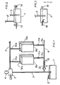
- the installation according to the invention comprises at its lower part a reservoir of heat transfer fluid 1 which communicates with the outside air via a vent 2, so that the free surface of the fluid in the reservoir 1 is at atmospheric pressure.
- a rising pipe 3 plunges into the tank 1 and it is connected at its upper part to a vacuum pump 4 via a level controller 5 whose role will be explained below.
- a substantially horizontal supply pipe 6 is connected to the pipe 3 at its lower part and an outlet pipe 7, which is also substantially horizontal, is connected to this same rising pipe 3 at the level of the level controller 5.
- Between the pipes elements 6a and outlet 7 are mounted elements 8a, 8b, etc., by means of connection pipes 9a, 9b, etc. connecting elements 8a, 8b, etc. corresponding to the supply pipe 6 and connection pipes 10a, 10b, etc. connecting elements 8a, 8b, etc. corresponding to the outlet pipe 7.
- Valves 11a, 11b, etc. are respectively mounted on the connecting pipes 9a, 9b, etc.
- a circulation pump 12 and a heat exchanger 13 can be mounted at the inlet of the pipeline. inlet 6.
- each of the elements 8a, 8b, etc. consists of the member to be cooled or heated which is for example a computer electronic card 14a, 14b, etc. and to which a parallelepiped box 15a, 15b, etc. is applied. whose large corresponding face is open and which is provided with orifices for the connection of the pipes 9a, 9b, etc. and 10a, 10b, etc.
- Appropriate seals can be interposed between the members 14a, 14b, etc. and the corresponding boxes 8a, 8b, etc., which are interconnected by any suitable means such as screws, clamps, or any similar member.
- the operating mode of this installation is as follows: first, fill the reservoir 1 with fluid, then switch on the vacuum pump 4, so that the fluid is sucked into the entire installation, and the controller level 5 stops pump 4 as soon as the level is sufficient. Thanks to the circulation pump 12, the fluid passes through the elements 8a, 8b, etc. where it cools or heats the organs 14a, 14b, etc. Because the pressure of this fluid is lower than atmospheric pressure at this level, any leakage is impossible.
- vent 2 allowing the tank 1 to be brought to atmospheric pressure can be replaced by a more elaborate device which is shown in FIG. 2 and which comprises a regulator 15 which can be supplied with air, neutral gas or any other gas depending on the nature of the fluid used, and a pressure relief valve 16 connected to a discharge pipe or to a recovery system, these two members only working during variations in atmospheric pressure or temperature, or in the event of air entering the circuit.
- a regulator 15 which can be supplied with air, neutral gas or any other gas depending on the nature of the fluid used
- a pressure relief valve 16 connected to a discharge pipe or to a recovery system
- a simple constant level tank is used, the capacity of which may be lower than that of the installation. .
- This tank is then provided a water inlet 18 comprising a float valve and an overflow 19.
- the first is static, and it is the vapor pressure of the liquid used as a function of the temperature.
- the maximum height of the system can theoretically not exceed 8 meters for an atmospheric pressure equal to one bar.
- Another limit is dynamic: if the circulation pump 12 is used, pressure drops must be taken into account to determine the zones where it is desired to maintain a negative relative pressure.
Landscapes
- Engineering & Computer Science (AREA)
- Microelectronics & Electronic Packaging (AREA)
- Physics & Mathematics (AREA)
- Thermal Sciences (AREA)
Applications Claiming Priority (2)
| Application Number | Priority Date | Filing Date | Title |
|---|---|---|---|
| FR8605846A FR2602035B1 (fr) | 1986-04-23 | 1986-04-23 | Procede et installation de transfert de chaleur entre un fluide et un organe a refroidir ou rechauffer, par mise en depression du fluide par rapport a la pression atmospherique |
| FR8605846 | 1986-04-23 |
Publications (3)
| Publication Number | Publication Date |
|---|---|
| EP0243239A2 true EP0243239A2 (de) | 1987-10-28 |
| EP0243239A3 EP0243239A3 (en) | 1989-06-14 |
| EP0243239B1 EP0243239B1 (de) | 1994-06-22 |
Family
ID=9334526
Family Applications (1)
| Application Number | Title | Priority Date | Filing Date |
|---|---|---|---|
| EP19870400838 Expired - Lifetime EP0243239B1 (de) | 1986-04-23 | 1987-04-14 | Anlage zur Übertragung der Wärme zwischen einer Flüssigkeit und einem Organ zum Abkühlen oder zum Erwärmen durch Herabsetzen des Drucks der Flüssigkeit in Bezug auf den atmosphärischen Druck |
Country Status (3)
| Country | Link |
|---|---|
| EP (1) | EP0243239B1 (de) |
| DE (1) | DE3750099T2 (de) |
| FR (1) | FR2602035B1 (de) |
Cited By (17)
| Publication number | Priority date | Publication date | Assignee | Title |
|---|---|---|---|---|
| EP0488926A1 (de) * | 1990-11-30 | 1992-06-03 | Pau Urbina Casanovas | Verfahren zur Temperatursteigerung in einem geschlossenen Heizkreis, der auf einer beliebigen Wärmeenergiebasis arbeitet |
| GB2316237A (en) * | 1996-08-06 | 1998-02-18 | Advantest Corp | Cooling of electronic devices mounted on a circuit board |
| WO2000065890A1 (en) * | 1999-04-27 | 2000-11-02 | Abb Ab | A device at electrical apparatuses having a cooling arrangement and a method for avoiding losses of cooling medium |
| EP1380799A3 (de) * | 2002-07-11 | 2004-12-15 | Raytheon Company | Verfahren und Vorrichtung zum Kühlen mit einem Kühlmittel mit einem Druck unterhalb des Umgebungsdrucks |
| US6937471B1 (en) | 2002-07-11 | 2005-08-30 | Raytheon Company | Method and apparatus for removing heat from a circuit |
| US6957550B2 (en) | 2003-05-19 | 2005-10-25 | Raytheon Company | Method and apparatus for extracting non-condensable gases in a cooling system |
| US7254957B2 (en) | 2005-02-15 | 2007-08-14 | Raytheon Company | Method and apparatus for cooling with coolant at a subambient pressure |
| WO2009055142A1 (en) * | 2007-10-25 | 2009-04-30 | Raytheon Company | System and method for cooling structures having both an active state and an inactive state |
| GB2465140A (en) * | 2008-10-30 | 2010-05-12 | Aqua Cooling Solutions Ltd | Heat exchange apparatus for an electronic or computer system |
| WO2010086098A1 (de) * | 2009-02-02 | 2010-08-05 | Knürr AG | Verfahren und anordnung zum kühlen von elektrischen und elektronischen bauelementen und moduleinheiten in geräteschränken |
| US7908874B2 (en) | 2006-05-02 | 2011-03-22 | Raytheon Company | Method and apparatus for cooling electronics with a coolant at a subambient pressure |
| US7921655B2 (en) | 2007-09-21 | 2011-04-12 | Raytheon Company | Topping cycle for a sub-ambient cooling system |
| US7934386B2 (en) | 2008-02-25 | 2011-05-03 | Raytheon Company | System and method for cooling a heat generating structure |
| US8341965B2 (en) | 2004-06-24 | 2013-01-01 | Raytheon Company | Method and system for cooling |
| US8651172B2 (en) | 2007-03-22 | 2014-02-18 | Raytheon Company | System and method for separating components of a fluid coolant for cooling a structure |
| US9383145B2 (en) | 2005-11-30 | 2016-07-05 | Raytheon Company | System and method of boiling heat transfer using self-induced coolant transport and impingements |
| CN106465562A (zh) * | 2015-10-23 | 2017-02-22 | 华为技术有限公司 | 热管散热系统及电力设备 |
Family Cites Families (4)
| Publication number | Priority date | Publication date | Assignee | Title |
|---|---|---|---|---|
| US3481393A (en) * | 1968-01-15 | 1969-12-02 | Ibm | Modular cooling system |
| US3757530A (en) * | 1972-04-12 | 1973-09-11 | Control Data Corp | Cooling system for data processing apparatus |
| US3992894A (en) * | 1975-12-22 | 1976-11-23 | International Business Machines Corporation | Inter-active dual loop cooling system |
| US4698728A (en) * | 1986-10-14 | 1987-10-06 | Unisys Corporation | Leak tolerant liquid cooling system |
-
1986
- 1986-04-23 FR FR8605846A patent/FR2602035B1/fr not_active Expired - Fee Related
-
1987
- 1987-04-14 EP EP19870400838 patent/EP0243239B1/de not_active Expired - Lifetime
- 1987-04-14 DE DE19873750099 patent/DE3750099T2/de not_active Expired - Fee Related
Cited By (26)
| Publication number | Priority date | Publication date | Assignee | Title |
|---|---|---|---|---|
| EP0488926A1 (de) * | 1990-11-30 | 1992-06-03 | Pau Urbina Casanovas | Verfahren zur Temperatursteigerung in einem geschlossenen Heizkreis, der auf einer beliebigen Wärmeenergiebasis arbeitet |
| GB2316237A (en) * | 1996-08-06 | 1998-02-18 | Advantest Corp | Cooling of electronic devices mounted on a circuit board |
| US6052284A (en) * | 1996-08-06 | 2000-04-18 | Advantest Corporation | Printed circuit board with electronic devices mounted thereon |
| GB2316237B (en) * | 1996-08-06 | 2001-09-12 | Advantest Corp | Printed circuit board with electronic devices mounted thereon |
| WO2000065890A1 (en) * | 1999-04-27 | 2000-11-02 | Abb Ab | A device at electrical apparatuses having a cooling arrangement and a method for avoiding losses of cooling medium |
| US7607475B2 (en) | 2002-07-11 | 2009-10-27 | Raytheon Company | Apparatus for cooling with coolant at subambient pressure |
| EP1380799A3 (de) * | 2002-07-11 | 2004-12-15 | Raytheon Company | Verfahren und Vorrichtung zum Kühlen mit einem Kühlmittel mit einem Druck unterhalb des Umgebungsdrucks |
| US6937471B1 (en) | 2002-07-11 | 2005-08-30 | Raytheon Company | Method and apparatus for removing heat from a circuit |
| US7000691B1 (en) | 2002-07-11 | 2006-02-21 | Raytheon Company | Method and apparatus for cooling with coolant at a subambient pressure |
| US6957550B2 (en) | 2003-05-19 | 2005-10-25 | Raytheon Company | Method and apparatus for extracting non-condensable gases in a cooling system |
| US8341965B2 (en) | 2004-06-24 | 2013-01-01 | Raytheon Company | Method and system for cooling |
| US7254957B2 (en) | 2005-02-15 | 2007-08-14 | Raytheon Company | Method and apparatus for cooling with coolant at a subambient pressure |
| US9383145B2 (en) | 2005-11-30 | 2016-07-05 | Raytheon Company | System and method of boiling heat transfer using self-induced coolant transport and impingements |
| US8490418B2 (en) | 2006-05-02 | 2013-07-23 | Raytheon Company | Method and apparatus for cooling electronics with a coolant at a subambient pressure |
| US7908874B2 (en) | 2006-05-02 | 2011-03-22 | Raytheon Company | Method and apparatus for cooling electronics with a coolant at a subambient pressure |
| US8651172B2 (en) | 2007-03-22 | 2014-02-18 | Raytheon Company | System and method for separating components of a fluid coolant for cooling a structure |
| US7921655B2 (en) | 2007-09-21 | 2011-04-12 | Raytheon Company | Topping cycle for a sub-ambient cooling system |
| US9644869B2 (en) | 2007-10-25 | 2017-05-09 | Raytheon Company | System and method for cooling structures having both an active state and an inactive state |
| WO2009055142A1 (en) * | 2007-10-25 | 2009-04-30 | Raytheon Company | System and method for cooling structures having both an active state and an inactive state |
| US7934386B2 (en) | 2008-02-25 | 2011-05-03 | Raytheon Company | System and method for cooling a heat generating structure |
| US8582295B2 (en) | 2008-10-30 | 2013-11-12 | Aqua Cooling Solutions Ltd. | Electronic system |
| GB2465140B (en) * | 2008-10-30 | 2011-04-13 | Aqua Cooling Solutions Ltd | An electronic system |
| GB2465140A (en) * | 2008-10-30 | 2010-05-12 | Aqua Cooling Solutions Ltd | Heat exchange apparatus for an electronic or computer system |
| WO2010086098A1 (de) * | 2009-02-02 | 2010-08-05 | Knürr AG | Verfahren und anordnung zum kühlen von elektrischen und elektronischen bauelementen und moduleinheiten in geräteschränken |
| CN106465562A (zh) * | 2015-10-23 | 2017-02-22 | 华为技术有限公司 | 热管散热系统及电力设备 |
| US10470339B2 (en) | 2015-10-23 | 2019-11-05 | Huawei Technologies Co., Ltd. | Heat-pipe heat dissipation system and power device |
Also Published As
| Publication number | Publication date |
|---|---|
| DE3750099T2 (de) | 1994-10-13 |
| DE3750099D1 (de) | 1994-07-28 |
| EP0243239A3 (en) | 1989-06-14 |
| FR2602035A1 (fr) | 1988-01-29 |
| EP0243239B1 (de) | 1994-06-22 |
| FR2602035B1 (fr) | 1990-05-25 |
Similar Documents
| Publication | Publication Date | Title |
|---|---|---|
| EP0243239A2 (de) | Anlage zur Übertragung der Wärme zwischen einer Flüssigkeit und einem Organ zum Abkühlen oder zum Erwärmen durch Herabsetzen des Drucks der Flüssigkeit in Bezug auf den atmosphärischen Druck | |
| CN100519402C (zh) | 二次安全壳系统和方法 | |
| EP3690303B1 (de) | Verfahren und vorrichtung zum füllen eines flüssiggasbehälters | |
| FR2641267A1 (fr) | Systeme pour une recuperation sure de vapeurs, particulierement pour les installations de distribution de carburant | |
| EP0669523B1 (de) | Anordnung zur Messung des Flüssigkeitsniveaus in einem Behälter | |
| WO2021116629A1 (fr) | Dispositif de refroidissement d'un pack-batteries | |
| FR2997739A1 (fr) | Compresseur comprenant un equilibrage de poussee | |
| FR2640362A1 (fr) | Dispositif de surveillance pour detecter les fuites d'air dans un systeme de refrigeration a circuit ferme | |
| FR2514114A1 (fr) | Circuit ferme de pompe a chaleur ou a froid | |
| EP0528726A1 (de) | Verfahren und Vorrichtung zur Steuerung einer Pumpen-Anlage und Nachweiselement für eine derartige Anlage | |
| FR3125881A1 (fr) | Dispositif de détection de fuites pour pack batterie de véhicule automobile | |
| EP0489628A1 (de) | Verdampfungskühlverfahren für eine Brennkraftmaschine und Einrichtung zur Durchführung dieses Verfahrens | |
| FR2578325A1 (fr) | Ligne de prelevement et de conditionnement de gaz en vue de son analyse. | |
| FR3074531A1 (fr) | Installation pour une turbomachine | |
| WO2010061109A2 (fr) | Procédé d'évaluation de l'étanchéité d'une enceinte d'un servomoteur | |
| WO2023111414A1 (fr) | Circuit de refroidissement pour système d'alimentation et de refroidissement d'un gaz | |
| FR2786852A1 (fr) | Pompe de relevage des condensats a capteur piezo resistant pour installations de climatisation | |
| EP1842013B1 (de) | Installation zum kryogenen kühlen für supraleitervorrichtung | |
| FR3112028A1 (fr) | Dispositif de régulation thermique. | |
| EP0010464A1 (de) | Startverfahren und -vorrichtung für eine Pumpe mit kryogener Flüssigkeit | |
| FR3001792B1 (fr) | Procede de controle automatique de la vidange d'une installation solaire thermique auto-vidangeable et installation equipee pour la mise en oeuvre d'un tel procede | |
| FR2705523A1 (fr) | Installation de refroidissement, notamment pour une carte de circuit électronique. | |
| WO2025257500A1 (fr) | Systeme d'alimentation en gaz d'un apapreil consommateur de gaz d'un ouvrage flottant | |
| WO2023174682A1 (fr) | Dispositif de degazage d'hydrogene liquide | |
| EP0306467B1 (de) | Automatische Trennvorrichtung für doppelwandige Flüssigkeitstransportnetze |
Legal Events
| Date | Code | Title | Description |
|---|---|---|---|
| PUAI | Public reference made under article 153(3) epc to a published international application that has entered the european phase |
Free format text: ORIGINAL CODE: 0009012 |
|
| AK | Designated contracting states |
Kind code of ref document: A2 Designated state(s): BE CH DE GB LI LU NL |
|
| PUAL | Search report despatched |
Free format text: ORIGINAL CODE: 0009013 |
|
| AK | Designated contracting states |
Kind code of ref document: A3 Designated state(s): BE CH DE GB LI LU NL |
|
| 17P | Request for examination filed |
Effective date: 19890822 |
|
| 17Q | First examination report despatched |
Effective date: 19920324 |
|
| GRAA | (expected) grant |
Free format text: ORIGINAL CODE: 0009210 |
|
| AK | Designated contracting states |
Kind code of ref document: B1 Designated state(s): BE CH DE GB LI LU NL |
|
| PG25 | Lapsed in a contracting state [announced via postgrant information from national office to epo] |
Ref country code: NL Effective date: 19940622 |
|
| GBT | Gb: translation of ep patent filed (gb section 77(6)(a)/1977) |
Effective date: 19940628 |
|
| REF | Corresponds to: |
Ref document number: 3750099 Country of ref document: DE Date of ref document: 19940728 |
|
| NLV1 | Nl: lapsed or annulled due to failure to fulfill the requirements of art. 29p and 29m of the patents act | ||
| PLBE | No opposition filed within time limit |
Free format text: ORIGINAL CODE: 0009261 |
|
| STAA | Information on the status of an ep patent application or granted ep patent |
Free format text: STATUS: NO OPPOSITION FILED WITHIN TIME LIMIT |
|
| PG25 | Lapsed in a contracting state [announced via postgrant information from national office to epo] |
Ref country code: LU Free format text: LAPSE BECAUSE OF NON-PAYMENT OF DUE FEES Effective date: 19950430 |
|
| 26N | No opposition filed | ||
| PGFP | Annual fee paid to national office [announced via postgrant information from national office to epo] |
Ref country code: BE Payment date: 19990323 Year of fee payment: 13 |
|
| PGFP | Annual fee paid to national office [announced via postgrant information from national office to epo] |
Ref country code: GB Payment date: 19990415 Year of fee payment: 13 |
|
| PGFP | Annual fee paid to national office [announced via postgrant information from national office to epo] |
Ref country code: DE Payment date: 19990421 Year of fee payment: 13 |
|
| PGFP | Annual fee paid to national office [announced via postgrant information from national office to epo] |
Ref country code: CH Payment date: 19990701 Year of fee payment: 13 |
|
| PG25 | Lapsed in a contracting state [announced via postgrant information from national office to epo] |
Ref country code: GB Free format text: LAPSE BECAUSE OF NON-PAYMENT OF DUE FEES Effective date: 20000414 |
|
| PG25 | Lapsed in a contracting state [announced via postgrant information from national office to epo] |
Ref country code: LI Free format text: LAPSE BECAUSE OF NON-PAYMENT OF DUE FEES Effective date: 20000430 Ref country code: CH Free format text: LAPSE BECAUSE OF NON-PAYMENT OF DUE FEES Effective date: 20000430 Ref country code: BE Free format text: LAPSE BECAUSE OF NON-PAYMENT OF DUE FEES Effective date: 20000430 |
|
| BERE | Be: lapsed |
Owner name: BOSTEELS MICHEL Effective date: 20000430 |
|
| GBPC | Gb: european patent ceased through non-payment of renewal fee |
Effective date: 20000414 |
|
| REG | Reference to a national code |
Ref country code: CH Ref legal event code: PL |
|
| PG25 | Lapsed in a contracting state [announced via postgrant information from national office to epo] |
Ref country code: DE Free format text: LAPSE BECAUSE OF NON-PAYMENT OF DUE FEES Effective date: 20010201 |