EP0243092A2 - Schubladen - Google Patents
Schubladen Download PDFInfo
- Publication number
- EP0243092A2 EP0243092A2 EP87303343A EP87303343A EP0243092A2 EP 0243092 A2 EP0243092 A2 EP 0243092A2 EP 87303343 A EP87303343 A EP 87303343A EP 87303343 A EP87303343 A EP 87303343A EP 0243092 A2 EP0243092 A2 EP 0243092A2
- Authority
- EP
- European Patent Office
- Prior art keywords
- panels
- drawer
- perimeter
- spigots
- panel
- Prior art date
- Legal status (The legal status is an assumption and is not a legal conclusion. Google has not performed a legal analysis and makes no representation as to the accuracy of the status listed.)
- Withdrawn
Links
- 238000010276 construction Methods 0.000 description 6
- 239000000463 material Substances 0.000 description 2
- 229920003023 plastic Polymers 0.000 description 1
- 239000004033 plastic Substances 0.000 description 1
- 238000005728 strengthening Methods 0.000 description 1
- 239000000725 suspension Substances 0.000 description 1
Images
Classifications
-
- A—HUMAN NECESSITIES
- A47—FURNITURE; DOMESTIC ARTICLES OR APPLIANCES; COFFEE MILLS; SPICE MILLS; SUCTION CLEANERS IN GENERAL
- A47B—TABLES; DESKS; OFFICE FURNITURE; CABINETS; DRAWERS; GENERAL DETAILS OF FURNITURE
- A47B88/00—Drawers for tables, cabinets or like furniture; Guides for drawers
- A47B88/90—Constructional details of drawers
- A47B88/941—Drawers being constructed from two or more parts
Definitions
- This invention relates to a drawer.
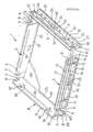
- the invention consists in a drawer comprising four perimeter panels, said perimeter panels having spigots thereon and/or apertures thereon, selected spigots on one panel being passed through selected aperture to locate said perimeter panels, each perimeter panel having a slot adjacent the lower edge in use of its inwardly facing face so that said slots receive the edges of a panel forming a drawer bottom.
- a drawer 1 which is formed from perimeter panels and a base panel.
- Four perimeter panels are provided which comprise a pair of end panels formed by a front panel 2 and a rear panel 3 and a pair of side panels 4.
- the panels have a combination of spigots and apertures and in the preferred form a pair of perimeter panels have spigots extending therefrom and these are preferably the front panel 2 and rear panel 3.
- the remaining panels preferably the side panels 4 have apertures therein which receive the spigots.
- the perimeter panels are preferable moulded from, for example, a suitable plastics material so that the side panels 4 are substantially identical and also desirably the end panels 2 and 3 are identical.
- Each end panel 2 or 3 preferably provides a pair of spigots 5 and 6 at each end and in cross section each spigot is preferably in the form of a bifurcated arrowhead having a pair of forwardly extending tapered faces 7 with a substantially vertical face at 8 therebehind.
- a slot 9 is provided between each part of the arrowhead.
- the spigots 5 and 6 are preferably formed integrally with the end panels 2 and 3.
- the side panels 4 have apertures 10 and 11 therein through which the spigots 5 and 6 pass. The height of the apertures 10 and 11 is preferably substantially equal to but a little greater than the thickness of the spigots 5 and 6 behind the arrowhead.
- the slot 9 allows the arrowhead parts to be forced inwardly to allow the arrowheads to pass through the apertures 10 and 11 where the substantially vertical faces at 8 become caught by the material defining the perimeter of the apertures 10 and 11. Further spigots can be provided towards the bottom of the panels if desired.
- the perimeter panels 2, 3 and 4 are preferably formed so that they provide an inwardly substantially planar face with strengthening constructions on the rear face such as, for example, a plurality of substantially horizontal ribs 12, 13, 14 and 15 for example with for example substantially vertical end ribs 16 and if desired intermediate vertical ribs 17 which may carry receiving members for example in the form of short tubes such as 18 to receive screws or the like passing through a facing panel which can form a decorative front to the construction.
- the side panels can be formed in a similar way but in a preferred construction a recess is provided at 20 into which a plurality of wheels, rollers or the like are positioned and shown in the figure are a plurality of wheels or rollers such as wheels 21 which are fitted into the recess 20 but spaced upwardly from the lower surface 22 of the recess so that an arm of the like provided on a carcass into which the drawer is positioned becomes positioned in the gap between the face 20 and the wheels 21 so that the wheels 21 will run on that arm.
- the perimeter panels have a slot 23 therein adjacent the lower edge thereof in use. Into the slot 23 is positioned a substantially planar panel 24 which forms the drawer bottom. This can be further located by for example staples or other fixing devices passing through a flange 25 which forms the lower edge in use of the slot 23.
- drawer slides of substantially known type may be engaged with the carcass so parts of the sides may run on or in the slides in use.
- the sides 4 preferably carry cut outs such as cut outs 27 which will enable a locking member associated with the carcass to be inserted therein or removed therefrom to allow locking of the drawer.
- the locking member may comprise a simple gang lock such as a bar with a number of flanges thereon mounted on the drawer carcass.
- Each perimeter panel may have a groove 30 therein and in particular the side panels 4 so that a drawer divider or other item can have parts thereof frictionally engaged into the recess.
- the side panels 4 in particular, but also if desired the front panels 2 and 3, may have a raised rib 31 which may be utilised for suspension files or mounting of a tray, for example, a pencil tray or the like.
- the spigots 5 and 6 are positioned at the ends of the end panels 2 and 3 and also within the boundaries of the upper half of those panels further aperture sets 35, 36 and 37, 38 allow the ends 2 and 3 to be inwardly displayed if required.
- a recess 40 is provided in the inwardly facing bottom flange 23. This enables sides 4 and ends 2 and 3 to be stacked one upon the other to increase the depth of the drawers.
- Removal of the drawer from the carcass can be substantially prevented by providing stops on the drawer and also stops on, for example, runners.
- the stops in the draw can be formed by necked member passable into a selected slot 42.
- the necked member may carry a resilient part which strikes in use the slot on the runner.
- the front and rear panels 2 and 3 and the side panels 4 are interconnected as above described about a base panel 24.
- the drawers may have a front decorative member engaged thereto by the passage of, for example, screws into the cylindrical parts 18.
- the drawer is then positioned in a suitable carcass and used substantially in the known manner.
- a facility which permits only one drawer to be opened fully at a time and to this end in the front panel 2 and rear panel 3 may be provided a pair of vertical ribs 32 into which is positioned a bar 33 shown in the form of a half round.
- a drawer which has the advantage that it can be simply erected from moulded components whilst having provision for the mounting of rollers or wheels if required.
- the construction is therefore simple to make and because of the moulded components can be made with substantially regularity as to size.
Landscapes
- Drawers Of Furniture (AREA)
Applications Claiming Priority (2)
| Application Number | Priority Date | Filing Date | Title |
|---|---|---|---|
| NZ215834 | 1986-04-15 | ||
| NZ21583486 | 1986-04-15 |
Publications (2)
| Publication Number | Publication Date |
|---|---|
| EP0243092A2 true EP0243092A2 (de) | 1987-10-28 |
| EP0243092A3 EP0243092A3 (de) | 1988-01-13 |
Family
ID=19921615
Family Applications (1)
| Application Number | Title | Priority Date | Filing Date |
|---|---|---|---|
| EP87303343A Withdrawn EP0243092A3 (de) | 1986-04-15 | 1987-04-15 | Schubladen |
Country Status (3)
| Country | Link |
|---|---|
| EP (1) | EP0243092A3 (de) |
| JP (1) | JPS6323616A (de) |
| AU (1) | AU7156387A (de) |
Cited By (1)
| Publication number | Priority date | Publication date | Assignee | Title |
|---|---|---|---|---|
| US5538339A (en) * | 1992-07-02 | 1996-07-23 | Julius Blum Gesellschaft M.B.H. | Drawer construction set |
Family Cites Families (4)
| Publication number | Priority date | Publication date | Assignee | Title |
|---|---|---|---|---|
| DE1654545A1 (de) * | 1967-06-09 | 1971-05-19 | Wolfgang Sandrock | Kunststoffschubkasten,hergestellt aus Seitenelementen im Steckmontagesystem |
| FR2204957A5 (de) * | 1972-10-26 | 1974-05-24 | Sarrazin Nicole | |
| FR2355482A1 (fr) * | 1975-10-31 | 1978-01-20 | Krieg & Zivy Ind | Tiroir a monter |
| US4379604A (en) * | 1980-11-25 | 1983-04-12 | Julius Blum Ges.M.B.H. | Drawer |
-
1987
- 1987-04-15 JP JP62092956A patent/JPS6323616A/ja active Pending
- 1987-04-15 AU AU71563/87A patent/AU7156387A/en not_active Abandoned
- 1987-04-15 EP EP87303343A patent/EP0243092A3/de not_active Withdrawn
Cited By (1)
| Publication number | Priority date | Publication date | Assignee | Title |
|---|---|---|---|---|
| US5538339A (en) * | 1992-07-02 | 1996-07-23 | Julius Blum Gesellschaft M.B.H. | Drawer construction set |
Also Published As
| Publication number | Publication date |
|---|---|
| JPS6323616A (ja) | 1988-01-30 |
| AU7156387A (en) | 1987-10-22 |
| EP0243092A3 (de) | 1988-01-13 |
Similar Documents
| Publication | Publication Date | Title |
|---|---|---|
| US3779623A (en) | Sectional rack | |
| US4905847A (en) | Display shelf system | |
| US10959544B2 (en) | Magnetic tool holder | |
| US4988003A (en) | Stackable tray carrying units | |
| US6082557A (en) | Shelving system | |
| DE69408572T2 (de) | Zusammenbau von dünnen flachen platten | |
| US6695418B2 (en) | Modular shelving with cabinet | |
| US6561601B1 (en) | Quick-assembly storage unit | |
| US3832957A (en) | Interlocking display shelf arrangement | |
| US4083456A (en) | Terraced modular rack assembly | |
| EP1174060A1 (de) | Produkttragplatte mit einem Trägerelement | |
| US4808875A (en) | Locker shelf and drawer assembly | |
| US4664283A (en) | User assembled desk top file | |
| US5630658A (en) | Hemmed edge file holder | |
| US4069941A (en) | Engageable card racks | |
| US5287974A (en) | Catalog holder | |
| US5031974A (en) | Organizer cabinet | |
| US3582170A (en) | Display table | |
| US4062302A (en) | Shelving assembly with removable divider inserts | |
| US4750625A (en) | Shelf and divider arrangement | |
| US4379604A (en) | Drawer | |
| US5358321A (en) | Modular multi-media cabinet | |
| US1939651A (en) | Compartment box | |
| EP0243092A2 (de) | Schubladen | |
| EP0174416B1 (de) | Gestell für Anzeigetafel |
Legal Events
| Date | Code | Title | Description |
|---|---|---|---|
| PUAI | Public reference made under article 153(3) epc to a published international application that has entered the european phase |
Free format text: ORIGINAL CODE: 0009012 |
|
| AK | Designated contracting states |
Kind code of ref document: A2 Designated state(s): AT BE CH DE ES FR GB GR IT LI LU NL SE |
|
| PUAL | Search report despatched |
Free format text: ORIGINAL CODE: 0009013 |
|
| AK | Designated contracting states |
Kind code of ref document: A3 Designated state(s): AT BE CH DE ES FR GB GR IT LI LU NL SE |
|
| STAA | Information on the status of an ep patent application or granted ep patent |
Free format text: STATUS: THE APPLICATION IS DEEMED TO BE WITHDRAWN |
|
| 18D | Application deemed to be withdrawn |
Effective date: 19880914 |
|
| RIN1 | Information on inventor provided before grant (corrected) |
Inventor name: RASMUSSEN, JOHN Inventor name: YATES, SCOTT WRIGHT |