EP0242894A1 - Druckwandler mit optischen Fasern - Google Patents
Druckwandler mit optischen Fasern Download PDFInfo
- Publication number
- EP0242894A1 EP0242894A1 EP87200398A EP87200398A EP0242894A1 EP 0242894 A1 EP0242894 A1 EP 0242894A1 EP 87200398 A EP87200398 A EP 87200398A EP 87200398 A EP87200398 A EP 87200398A EP 0242894 A1 EP0242894 A1 EP 0242894A1
- Authority
- EP
- European Patent Office
- Prior art keywords
- light
- recesses
- pressure sensor
- optic fibre
- pressure
- Prior art date
- Legal status (The legal status is an assumption and is not a legal conclusion. Google has not performed a legal analysis and makes no representation as to the accuracy of the status listed.)
- Granted
Links
- 230000003287 optical effect Effects 0.000 title description 2
- 238000004804 winding Methods 0.000 claims abstract description 40
- 238000005192 partition Methods 0.000 claims abstract description 13
- 239000013013 elastic material Substances 0.000 claims abstract description 5
- 239000000835 fiber Substances 0.000 claims description 46
- 230000008859 change Effects 0.000 abstract description 6
- 238000012937 correction Methods 0.000 description 3
- 238000010586 diagram Methods 0.000 description 3
- 229910000831 Steel Inorganic materials 0.000 description 2
- 230000000694 effects Effects 0.000 description 2
- 238000001914 filtration Methods 0.000 description 2
- 238000004519 manufacturing process Methods 0.000 description 2
- 239000000463 material Substances 0.000 description 2
- 230000004044 response Effects 0.000 description 2
- 239000010959 steel Substances 0.000 description 2
- XUIMIQQOPSSXEZ-UHFFFAOYSA-N Silicon Chemical compound [Si] XUIMIQQOPSSXEZ-UHFFFAOYSA-N 0.000 description 1
- 230000009471 action Effects 0.000 description 1
- 239000000853 adhesive Substances 0.000 description 1
- 230000001070 adhesive effect Effects 0.000 description 1
- 230000008901 benefit Effects 0.000 description 1
- 230000008878 coupling Effects 0.000 description 1
- 238000010168 coupling process Methods 0.000 description 1
- 238000005859 coupling reaction Methods 0.000 description 1
- 230000007613 environmental effect Effects 0.000 description 1
- 239000011521 glass Substances 0.000 description 1
- 230000006872 improvement Effects 0.000 description 1
- 238000005259 measurement Methods 0.000 description 1
- 238000000034 method Methods 0.000 description 1
- 238000012545 processing Methods 0.000 description 1
- 238000007789 sealing Methods 0.000 description 1
- 229910052710 silicon Inorganic materials 0.000 description 1
- 239000010703 silicon Substances 0.000 description 1
- 239000002356 single layer Substances 0.000 description 1
- 229920002994 synthetic fiber Polymers 0.000 description 1
- 238000012546 transfer Methods 0.000 description 1
Images

Classifications
-
- G—PHYSICS
- G01—MEASURING; TESTING
- G01L—MEASURING FORCE, STRESS, TORQUE, WORK, MECHANICAL POWER, MECHANICAL EFFICIENCY, OR FLUID PRESSURE
- G01L11/00—Measuring steady or quasi-steady pressure of a fluid or a fluent solid material by means not provided for in group G01L7/00 or G01L9/00
- G01L11/02—Measuring steady or quasi-steady pressure of a fluid or a fluent solid material by means not provided for in group G01L7/00 or G01L9/00 by optical means
- G01L11/025—Measuring steady or quasi-steady pressure of a fluid or a fluent solid material by means not provided for in group G01L7/00 or G01L9/00 by optical means using a pressure-sensitive optical fibre
-
- G—PHYSICS
- G01—MEASURING; TESTING
- G01L—MEASURING FORCE, STRESS, TORQUE, WORK, MECHANICAL POWER, MECHANICAL EFFICIENCY, OR FLUID PRESSURE
- G01L9/00—Measuring steady of quasi-steady pressure of fluid or fluent solid material by electric or magnetic pressure-sensitive elements; Transmitting or indicating the displacement of mechanical pressure-sensitive elements, used to measure the steady or quasi-steady pressure of a fluid or fluent solid material, by electric or magnetic means
- G01L9/0001—Transmitting or indicating the displacement of elastically deformable gauges by electric, electro-mechanical, magnetic or electro-magnetic means
- G01L9/0007—Transmitting or indicating the displacement of elastically deformable gauges by electric, electro-mechanical, magnetic or electro-magnetic means using photoelectric means
Definitions
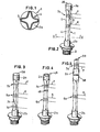
- the present invention relates to a pressure sensor, comprising a longitudinal hollow body of elastic material, closed off by a partition, the body having two tubular portions, one of which is to be connected to a pressure source, the body comprising over a part of its length a number of recesses which are defined by more or less sharp, longitudinally extending edges, between which the distance changes in accordance with the pressure to be measured, and an optic fibre with a winding portion around the recesses, connected at one end with a light source and at the other end with a light meter for measuring the quantity of light from the light source transmitted through the fibre.
- Such a pressure sensor is known from NL-A-84.00063, in which a similar longitudinal body has been developed with an optic fibre for determining the pressure.
- This device has some shortcomings. If, for example, this pressure sensor is used to determine pressure in an environment of highly variable temperatures, as is the case with gas exploration, the response of such a sensor will not only contain information on volume variations on account of the pressure, but it will also be affected by volume variations on account of the temperature.
- a proposal to compensate temperature is described in NL-A-84.00063, the heat expansion of the body at the level of the recesses is by no means removed. Moreover, this measure is in no way related to determining volume variations of the body as a result of temperature differences. It is also unclear what part of the winding around the body attributes to the sensor's response.
- the present invention aims to remove these restrictions, and for that purpose is characterized in that a sensor for temperature differences, comprising a second optic fibre, at one end connected to the light source and at the other end to a light meter for measuring the quantity of light from the light source transmitted through the fibre, which is mounted around the receses with at least one winding portion adjacent to one of the corresponding, tubular portions, the winding portion of the first-mentioned optic fibre being mounted all but halfway around the pressurized recesses disposed at the one side of the partition, and the winding portions of the two optic fibres having been secured at the beginning and end of each winding portion on the corresponding edges of the recesses.
- the recesses 4 end in the tubular portions 2a and 2b.
- the indicated recesses 4 are defined by more or less sharp edges 5. A different number of recesses, and, accordingly, a different number of edges can be provided if required.
- the longitudinal body 1 comprises two tubular portions 2a and 2b.
- the top one is closed off by a partition 28, the bottom one can, by means of an opening 3, e.g. a screw thread with pertaining sealing, be connected to a pressure source, which pressure has to be determined.
- An optic fibre as e.g. the fibre 6 in figure 2, is wound around the recesses 4, for which a desired winding tension can be chosen as required.
- the fibre portions of the winding will display kinks there where they extend over the edges 5 of the recesses 4. These kinks constitute spots where the light originating from the light source and sent into the fibre can escape; the extent to which this is effected is determined by the extent of the kink.
- the longitudinal body 1 with coupling 3 When the longitudinal body 1 with coupling 3 is connected to a pressure source, the distances between the edges 5 of the recesses 4 will change due to pressure variations. It will then be possible to measure the kink extent from the quantity of transmitted light from the light source changing accordingly, received in a light meter, e.g. a photo cell. The pressure variation and the change in quantity of transmitted light display a linear relation to a great extent, within a 0.5% margin.
- This pressure sensor is to be applied under circumstances in which the temperature can change varying from -20°C and +80° C .
- the distances between the edges 5 of the recesses 4 will not only change due to pressure differences, but also due to temperature differences. Therefore the light to be received through fibre 6 provides more than just information on the pressure to be determined.
- a correction for temperature differences is necessary. This relates to both the environmental temperature and the tem - perature of the medium which pressure has to be determined. Since the sensor is mounted at a dead end of the pressure conduit, where the medium does not flow, and the opted material, e.g. steel, allows for a good heat contact with the environment, an unambiguous correction can be obtained.
- this problem is solved by mounting a second fibre 7 around the recesses 4 of the longitudinal body 1 in those places, where the pressure influence is considerably smaller, particularly adjacent to a tubular portion 2a; precisely there the shape of the tubular portion 2 will still be of influence. Moreover it has appeared that the linearity margin has improved there op to 0.02%.
- both the fibres are preferably connected through a beam-splitter device with the same light source. Fluctuations in light emittance, if any, then occur simultaneously in both the measuring circuits.
- a light-emitting diode can be used as a light source.
- the accuracy of the sensor for temperature differences is further increased by winding the second fibre 7 in two portions 7b, 7d around the recesses 4 adjacent to the two tubular portions 2a, 2b on account of the improved linearity margin.
- the thus obtained measuring is then a measure of the average pressure variation adjacent to the tubular portion 2a, 2b.
- Each of the two winding portions 7b, 7d should, as indicated above, be secured.
- the connecting portion 7c between the two winding portions 7b, 7d will not affect the quantity of transmitted light since this portion extends substantially longitudinally and the kink strength of this portion is too small to present loss of light.
- Figure 4 represents a third embodiment. Unlike the above-described embodiments in figures 2 and 3 the winding portions 7a of the optic fibre 7 has been applied adjacent to the tubular portion 2a around the recesses 4 of a part of the longitudinal body 1, located on the other side of the partition 48, and thus not connected to the pressure source which pressure has to be determined, making the sensor for temperature differences independent of the pressure in the longitudinal body 1.
- This tubular portion 2a is preferably open, with an opening 49, so that the sensor for temperature differences is not pressure-related at all.
- the first optic fibre 6 is wound all but halfway at the portion of the recesses 4 connected to the pressure source for determining the pressure.
- the winding portion 7a of the sensor for temperature differences is applied around a portion of the body 1 with recesses 4, being separated from the recesses 4, said recesses being connected to the pressure source and wound with the first optic fibre 6, by a partition 58 of suitable material within the tubular portion 2a away from the connection to the pressure source.
- this sensor for temperature differences is also independent of the pressure in the longitudinal body, and again it can be open, with an opening 59, so that it is not pressure-related.
- partition 58 can easily be fitted.
- the winding portions 6a, 7a of the two optic fibres 6, 7 are applied, pre-tensioned and secured adjacent to the other tubular portion 2a and halfway the recesses 4 connected to the pressure source, respectively.
- the number of windings of the winding portions for both the first optic fibre 6 and the second optic fibre 7 preferably ranges between 10 and 30.
- multimode fibre of the known type is preferably used, with a core of quarts and a jacket of silicon glass.
- the fibre is coated with a synthetic material, e.g. a single layer of UV-acrylate, with which the fibre can be protected as desired and pre-tensioned around the recesses.
- the above-described pressure sensor e.g. with a length of about 10 cm and, at the level of the recesses, a diameter of about 0.8 cm can, based on the wall thickness of the recesses e.g. lying in the range of 0.1 and 0.5 mm and the pre-tension of the fibre, be adapted to determine pressures ranging between -1 and 100 bar.
- each optic fibre 6 and 7 is connected to a light source and a light meter, with which one single light source is sufficient.
- Figures 6-8 provide a few diagrams of possible circuits, in which the optical fibres 6, 7 have been incorporated.
- Figure 6 shows how light from a light source 100 is split into two beams through a connector-splitter device 60.
- Each beam is guided via the respective fibre 6, 7 to the respective winding portion 6a, 7a and then back to the light meters 101, 102, for measuring the difference in light on account of pressure and temperature variations and for measuring the difference in light on account of the temperature change only, respectively.
- the diagram of the circuit is divided in two blocks S and M, for the sensor portion and the measuring portion, respectively; in connector-splitter device 60 it is indicated by arrows how the beam is split.
- Figures 7 and 8 give two more embodiments of possible circuits. In these embodiments it is attained that the sensor portion S and the measuring portion M are only interconnected by two connecting points. In doing so, a clear improvement in the signal-to-noise ratio is obtained, while a simplified connection is established at the same time.
- winding portion 6a is connected to the light source 100 by mediation of the winding portion 7a.
- Light that has passed through winding portion 6a subsequently reaches the pertaining light meter 101.
- the light is passed via a connector-splitter device 70 to a light reversing device 71, after which it is again put through the action of the connector-splitter device 70, dividing the light over both the fibres 6 and 7.
- the direction of the light flow in the connector-splitter device 70 is indicated by sharply pointed arrows in the forward direction and by wide arrows in the reverse direction.
- the beam splitter 70 can either be connected to a mirror or to an optic fibre loop such as a light reversing device 71.
- FIG 8 an embodiment is shown in which the light from the light source 100 is passed through the connector-splitter device 60 in the indicated directions to the respective winding portions 6a and 7a. Every other end of the two fibres 6 and 7 is connected to a respective light reversing device 80, 81, after which the light is transferred back to the measuring portion M through said winding portions 6a and 7a. In this measuring portion the respective beams have to be split again in the respective connector-splitter devices 82 and 83 to reach the pertaining light meters 101 and 102.
- This circuit is also preferred to the one according to figure 6 for the same reasons as indicated in the description of figure 7. It can furtermore be remarked that the reversing devices 80 and 81 in the sensor portion S preferably are mirrors.
Landscapes
- Physics & Mathematics (AREA)
- General Physics & Mathematics (AREA)
- Measuring Fluid Pressure (AREA)
- Glass Compositions (AREA)
Priority Applications (1)
| Application Number | Priority Date | Filing Date | Title |
|---|---|---|---|
| AT87200398T ATE53121T1 (de) | 1986-03-04 | 1987-03-04 | Druckwandler mit optischen fasern. |
Applications Claiming Priority (2)
| Application Number | Priority Date | Filing Date | Title |
|---|---|---|---|
| NL8600547A NL8600547A (nl) | 1986-03-04 | 1986-03-04 | Druksensor. |
| NL8600547 | 1986-03-04 |
Publications (2)
| Publication Number | Publication Date |
|---|---|
| EP0242894A1 true EP0242894A1 (de) | 1987-10-28 |
| EP0242894B1 EP0242894B1 (de) | 1990-05-23 |
Family
ID=19847657
Family Applications (1)
| Application Number | Title | Priority Date | Filing Date |
|---|---|---|---|
| EP87200398A Expired - Lifetime EP0242894B1 (de) | 1986-03-04 | 1987-03-04 | Druckwandler mit optischen Fasern |
Country Status (4)
| Country | Link |
|---|---|
| EP (1) | EP0242894B1 (de) |
| AT (1) | ATE53121T1 (de) |
| DE (1) | DE3762923D1 (de) |
| NL (1) | NL8600547A (de) |
Cited By (4)
| Publication number | Priority date | Publication date | Assignee | Title |
|---|---|---|---|---|
| EP0387376A1 (de) * | 1989-03-15 | 1990-09-19 | GLÖTZL GESELLSCHAFT FÜR BAUMESSTECHNIK mbH | Drucksensor |
| FR2664384A1 (fr) * | 1990-07-09 | 1992-01-10 | Karlsruhe Augsburg Iweka | Capteur de pression a compensation de temperature. |
| GB2252402A (en) * | 1990-12-14 | 1992-08-05 | Al Mohanadi Abdul Latif Khalaf | Fibre optic sensor |
| JP2016099242A (ja) * | 2014-11-21 | 2016-05-30 | 住友電気工業株式会社 | 干渉型光ファイバセンサシステム及び干渉型光ファイバセンサヘッド |
Families Citing this family (1)
| Publication number | Priority date | Publication date | Assignee | Title |
|---|---|---|---|---|
| DE102008048578A1 (de) * | 2008-09-23 | 2010-03-25 | Asentec Gmbh | Messvorrichtung und Verfahren zur Messung |
Citations (2)
| Publication number | Priority date | Publication date | Assignee | Title |
|---|---|---|---|---|
| US2566326A (en) * | 1946-12-02 | 1951-09-04 | Jr Victor Guillemin | Strain gauge manometer |
| NL8400063A (nl) * | 1984-01-09 | 1985-08-01 | Stichting Ct Voor Micro Elektr | Een vervormbaar lichaam en een stralingsgeleidervezel omvattende drukmeter. |
-
1986
- 1986-03-04 NL NL8600547A patent/NL8600547A/nl not_active Application Discontinuation
-
1987
- 1987-03-04 DE DE8787200398T patent/DE3762923D1/de not_active Expired - Fee Related
- 1987-03-04 AT AT87200398T patent/ATE53121T1/de not_active IP Right Cessation
- 1987-03-04 EP EP87200398A patent/EP0242894B1/de not_active Expired - Lifetime
Patent Citations (2)
| Publication number | Priority date | Publication date | Assignee | Title |
|---|---|---|---|---|
| US2566326A (en) * | 1946-12-02 | 1951-09-04 | Jr Victor Guillemin | Strain gauge manometer |
| NL8400063A (nl) * | 1984-01-09 | 1985-08-01 | Stichting Ct Voor Micro Elektr | Een vervormbaar lichaam en een stralingsgeleidervezel omvattende drukmeter. |
Non-Patent Citations (1)
| Title |
|---|
| PATENT ABSTRACTS OF JAPAN, vol. 9, no. 296 (P-407)[2019], 22nd November 1985; & JP-A-60 133 336 (SHIMAZU SEISAKUSHO K.K.) 16-07-1985 * |
Cited By (5)
| Publication number | Priority date | Publication date | Assignee | Title |
|---|---|---|---|---|
| EP0387376A1 (de) * | 1989-03-15 | 1990-09-19 | GLÖTZL GESELLSCHAFT FÜR BAUMESSTECHNIK mbH | Drucksensor |
| FR2664384A1 (fr) * | 1990-07-09 | 1992-01-10 | Karlsruhe Augsburg Iweka | Capteur de pression a compensation de temperature. |
| EP0466623A1 (de) * | 1990-07-09 | 1992-01-15 | IWKA Aktiengesellschaft | Druckwandler mit optischen Fasern und Temperaturausgleich |
| GB2252402A (en) * | 1990-12-14 | 1992-08-05 | Al Mohanadi Abdul Latif Khalaf | Fibre optic sensor |
| JP2016099242A (ja) * | 2014-11-21 | 2016-05-30 | 住友電気工業株式会社 | 干渉型光ファイバセンサシステム及び干渉型光ファイバセンサヘッド |
Also Published As
| Publication number | Publication date |
|---|---|
| ATE53121T1 (de) | 1990-06-15 |
| DE3762923D1 (de) | 1990-06-28 |
| EP0242894B1 (de) | 1990-05-23 |
| NL8600547A (nl) | 1987-10-01 |
Similar Documents
| Publication | Publication Date | Title |
|---|---|---|
| US5118931A (en) | Fiber optic microbending sensor arrays including microbend sensors sensitive over different bands of wavelengths of light | |
| US6959604B2 (en) | Apparatus and method having an optical fiber disposed circumferentially around the pipe for measuring unsteady pressure within a pipe | |
| US3273447A (en) | Detection and measurement device having a small flexible fiber transmission line | |
| US6450037B1 (en) | Non-intrusive fiber optic pressure sensor for measuring unsteady pressures within a pipe | |
| US5877426A (en) | Bourdon tube pressure gauge with integral optical strain sensors for measuring tension or compressive strain | |
| US4734577A (en) | Continuous strain measurement along a span | |
| CN108507697B (zh) | 一种基于光纤传感的海水温深剖面测量系统 | |
| US6024488A (en) | Highly accurate temperature sensor using two fiber Bragg gratings | |
| US4829821A (en) | Optical fiber accelerometer | |
| US4462699A (en) | Fiber coupler temperature transducer | |
| US5168156A (en) | Reflective evanescent fiber-optic chemical sensor | |
| US4950886A (en) | Partially reflecting optical fiber splice for temperature and strain measurement | |
| JPS6354146A (ja) | 圧力モニタ装置 | |
| EP0242894A1 (de) | Druckwandler mit optischen Fasern | |
| HU196259B (en) | Optoelktromechanical measuring transducer | |
| KR910001090B1 (ko) | 광학섬유 결합기의 변환기 | |
| US5661246A (en) | Fiber optic displacement sensor for high temperature environment | |
| US5612778A (en) | Fiber optic sensor for multiple variables | |
| JPH11218458A (ja) | 圧力センサ及び圧力測定装置 | |
| AU718823B2 (en) | Sensor apparatus with polarization maintaining fibers | |
| US4641025A (en) | System for determining the position of the boundary between substances having different refractive indices | |
| JPS6257096A (ja) | 環境情報収集システム | |
| JPH03231116A (ja) | 光ファイバセンサ | |
| RU2039951C1 (ru) | Датчик температуры | |
| SU1760417A1 (ru) | Датчик давлени |
Legal Events
| Date | Code | Title | Description |
|---|---|---|---|
| PUAI | Public reference made under article 153(3) epc to a published international application that has entered the european phase |
Free format text: ORIGINAL CODE: 0009012 |
|
| AK | Designated contracting states |
Kind code of ref document: A1 Designated state(s): AT BE CH DE ES FR GB GR IT LI LU NL SE |
|
| 17P | Request for examination filed |
Effective date: 19880330 |
|
| 17Q | First examination report despatched |
Effective date: 19881227 |
|
| GRAA | (expected) grant |
Free format text: ORIGINAL CODE: 0009210 |
|
| AK | Designated contracting states |
Kind code of ref document: B1 Designated state(s): AT BE CH DE ES FR GB GR IT LI LU NL SE |
|
| PG25 | Lapsed in a contracting state [announced via postgrant information from national office to epo] |
Ref country code: IT Free format text: LAPSE BECAUSE OF FAILURE TO SUBMIT A TRANSLATION OF THE DESCRIPTION OR TO PAY THE FEE WITHIN THE PRE;WARNING: LAPSES OF ITALIAN PATENTS WITH EFFECTIVE DATE BEFORE 2007 MAY HAVE OCCURRED AT ANY TIME BEFORE 2007. THE CORRECT EFFECTIVE DATE MAY BE DIFFERENT FROM THE ONE RECORDED.SCRIBED TIME-LIMIT Effective date: 19900523 Ref country code: LI Effective date: 19900523 Ref country code: CH Effective date: 19900523 Ref country code: FR Effective date: 19900523 Ref country code: BE Effective date: 19900523 Ref country code: AT Effective date: 19900523 Ref country code: GR Free format text: LAPSE BECAUSE OF FAILURE TO SUBMIT A TRANSLATION OF THE DESCRIPTION OR TO PAY THE FEE WITHIN THE PRESCRIBED TIME-LIMIT Effective date: 19900523 Ref country code: SE Effective date: 19900523 |
|
| REF | Corresponds to: |
Ref document number: 53121 Country of ref document: AT Date of ref document: 19900615 Kind code of ref document: T |
|
| REF | Corresponds to: |
Ref document number: 3762923 Country of ref document: DE Date of ref document: 19900628 |
|
| REG | Reference to a national code |
Ref country code: CH Ref legal event code: PL |
|
| PG25 | Lapsed in a contracting state [announced via postgrant information from national office to epo] |
Ref country code: ES Free format text: LAPSE BECAUSE OF FAILURE TO SUBMIT A TRANSLATION OF THE DESCRIPTION OR TO PAY THE FEE WITHIN THE PRESCRIBED TIME-LIMIT Effective date: 19900903 |
|
| EN | Fr: translation not filed | ||
| PGFP | Annual fee paid to national office [announced via postgrant information from national office to epo] |
Ref country code: GB Payment date: 19910304 Year of fee payment: 5 |
|
| PLBE | No opposition filed within time limit |
Free format text: ORIGINAL CODE: 0009261 |
|
| STAA | Information on the status of an ep patent application or granted ep patent |
Free format text: STATUS: NO OPPOSITION FILED WITHIN TIME LIMIT |
|
| PG25 | Lapsed in a contracting state [announced via postgrant information from national office to epo] |
Ref country code: LU Free format text: LAPSE BECAUSE OF NON-PAYMENT OF DUE FEES Effective date: 19910331 |
|
| PGFP | Annual fee paid to national office [announced via postgrant information from national office to epo] |
Ref country code: NL Payment date: 19910331 Year of fee payment: 5 |
|
| PGFP | Annual fee paid to national office [announced via postgrant information from national office to epo] |
Ref country code: DE Payment date: 19910403 Year of fee payment: 5 |
|
| 26N | No opposition filed | ||
| PG25 | Lapsed in a contracting state [announced via postgrant information from national office to epo] |
Ref country code: GB Effective date: 19920304 |
|
| PG25 | Lapsed in a contracting state [announced via postgrant information from national office to epo] |
Ref country code: NL Effective date: 19921001 |
|
| GBPC | Gb: european patent ceased through non-payment of renewal fee | ||
| NLV4 | Nl: lapsed or anulled due to non-payment of the annual fee | ||
| PG25 | Lapsed in a contracting state [announced via postgrant information from national office to epo] |
Ref country code: DE Effective date: 19921201 |