EP0242673A2 - Unterdrückung der Oberschwingungen in einem Mikroschrittmotor - Google Patents
Unterdrückung der Oberschwingungen in einem Mikroschrittmotor Download PDFInfo
- Publication number
- EP0242673A2 EP0242673A2 EP87104981A EP87104981A EP0242673A2 EP 0242673 A2 EP0242673 A2 EP 0242673A2 EP 87104981 A EP87104981 A EP 87104981A EP 87104981 A EP87104981 A EP 87104981A EP 0242673 A2 EP0242673 A2 EP 0242673A2
- Authority
- EP
- European Patent Office
- Prior art keywords
- motor
- harmonics
- pole pieces
- microstepping
- stator
- Prior art date
- Legal status (The legal status is an assumption and is not a legal conclusion. Google has not performed a legal analysis and makes no representation as to the accuracy of the status listed.)
- Withdrawn
Links
- 230000001629 suppression Effects 0.000 title claims description 33
- 238000006073 displacement reaction Methods 0.000 claims abstract description 16
- 238000004804 winding Methods 0.000 claims description 18
- 230000008878 coupling Effects 0.000 claims description 3
- 238000010168 coupling process Methods 0.000 claims description 3
- 238000005859 coupling reaction Methods 0.000 claims description 3
- 238000000034 method Methods 0.000 description 23
- 230000000694 effects Effects 0.000 description 15
- 239000013598 vector Substances 0.000 description 7
- 230000009467 reduction Effects 0.000 description 4
- 101100521334 Mus musculus Prom1 gene Proteins 0.000 description 3
- 230000008901 benefit Effects 0.000 description 3
- 239000000696 magnetic material Substances 0.000 description 3
- XEEYBQQBJWHFJM-UHFFFAOYSA-N Iron Chemical compound [Fe] XEEYBQQBJWHFJM-UHFFFAOYSA-N 0.000 description 2
- 230000002411 adverse Effects 0.000 description 2
- 238000010276 construction Methods 0.000 description 2
- 238000010586 diagram Methods 0.000 description 2
- 230000006872 improvement Effects 0.000 description 2
- 230000000996 additive effect Effects 0.000 description 1
- 238000010420 art technique Methods 0.000 description 1
- 230000008859 change Effects 0.000 description 1
- 150000001875 compounds Chemical class 0.000 description 1
- 230000007423 decrease Effects 0.000 description 1
- 229910052742 iron Inorganic materials 0.000 description 1
- 230000002093 peripheral effect Effects 0.000 description 1
- 230000035699 permeability Effects 0.000 description 1
- 230000010363 phase shift Effects 0.000 description 1
- 238000004382 potting Methods 0.000 description 1
- 239000007787 solid Substances 0.000 description 1
- 230000001360 synchronised effect Effects 0.000 description 1
Images


Classifications
-
- H—ELECTRICITY
- H02—GENERATION; CONVERSION OR DISTRIBUTION OF ELECTRIC POWER
- H02K—DYNAMO-ELECTRIC MACHINES
- H02K37/00—Motors with rotor rotating step by step and without interrupter or commutator driven by the rotor, e.g. stepping motors
- H02K37/10—Motors with rotor rotating step by step and without interrupter or commutator driven by the rotor, e.g. stepping motors of permanent magnet type
- H02K37/12—Motors with rotor rotating step by step and without interrupter or commutator driven by the rotor, e.g. stepping motors of permanent magnet type with stationary armatures and rotating magnets
- H02K37/125—Magnet axially facing armature
-
- H—ELECTRICITY
- H02—GENERATION; CONVERSION OR DISTRIBUTION OF ELECTRIC POWER
- H02P—CONTROL OR REGULATION OF ELECTRIC MOTORS, ELECTRIC GENERATORS OR DYNAMO-ELECTRIC CONVERTERS; CONTROLLING TRANSFORMERS, REACTORS OR CHOKE COILS
- H02P8/00—Arrangements for controlling dynamo-electric motors rotating step by step
- H02P8/22—Control of step size; Intermediate stepping, e.g. microstepping
Definitions
- This invention relates to electric stepping motors suitable for use in stepper systems, and more particularly, to such motors and drive systems with suppressed harmonics for achieving effective microstepping.
- the most common stepper motor systems employ special two-phase synchronousmotors in combination with a phase current switching system.
- the basic full-step sequence is achieved by energizing phase A with a positive signal, then energizing phase B with a positive signal as phase A is turned off, then energizing phase A with a negative signal as phase B is turned off, then energizing phase B with a negative signal as phase A is turned off, and then repeating the sequence.
- the rotor of the motor is advanced incrementally by this four-step sequence, taking one full step at each change in the phase currents.
- the motor itself preferably includes a large number of poles so that one revolution of the motor includes a large number of incremental steps.
- An example of a suitable motor for such stepper applications is disclosed in US patent 4,330,727.
- More sophisticated stepper systems employ a control technique called "microstepping" where the motor can be controlled for positioning at a variety of positions intermediate the normal full-step positions.
- the number of intermediate positions is determined by the drive system controller.
- Such intermediate positions are achieved by proportioning the signals applied to the phase A and phase B windings to obtain a field vector as required for each intermediate point. Since the effect of the control is basically analog rather than digital, the presence of harmonics in the torque fundamental have a substantial effect on achieving position accuracy and, hence, are of great concern.
- the disadvantage of the technique described above is that the number of harmonics that can be suppressed depends upon the number of symmetrical groupings existing in the particular motor design. Also, the design can result in an undesirably large loss in.motor torque output.
- An object of the present invention is to provide a technique for torque harmonic suppression which does not depend upon movement of pole positions in accordance with symmetrical groupings.
- Another object of the invention is to provide a technique for suppressing torque harmonics to a selected degree.
- a further object is to provide a technique for achieving the desired degree of harmonic suppression together with the maximum fundamental torque component.
- microstepping control system of the invention comprising digital means for providing multiphase signals proportioned to provide a plurality of step values for motor positioning between 0 and 2 pi electrical degrees; drive circuit means for providing polyphase energizing currentsfor the motor corresponding to said step values; and a stepping motor including at least two phase windings connected to receive said energizing currents proportioned according to said step values; a plurality of pole pieces associated with each of said windings and providing the stepping
- motor airgap magnetic circuits for coupling said windings to said pole pieces; a rotor in said air gap being positionable in accordance with said proportional energizing currents applied to said windings, characterized in that at least some of said plurality of pole pieces are non-symmetrically displaced to reduce harmonics in the torque/displacement characteristic of said motor.
- stator pole teeth are located on centers separated from one another by 2 pi electrical degrees. With this spacing, the pole teeth have a maximum in-phase additive effect in producing torque in accordance with the energization signal. Unfortunately, this location of the pole teeth also tends to maximize the contribution of the harmonics to the torque/displacement characteristic of an uncompensated motor, and such harmonics have a substantial adverse effect when attempting to achieve accurate microstepping. Movement of a pole tooth away from the normal spacing at 2 pi electrical degrees reduces the vector sum of the torque harmonics and also decreases the vector sum of the fundamental torques. In accordance with the technique of this invention, the effect upon the fundamental and the effect upon each of the harmonics can be calculated for any shift of the pole tooth position from the normal position. The pole teeth positions can be moved individually or in combination.
- the most pronounced harmonics in a stepping motor are the third, fourth and fifth harmonics. Complete suppression of these harmonics reduces the magnitude of the output torque to about 76% of the normal value. Motors compensated according to the invention achieve suppression of the third, fourth and fifth harmonics to a level where the harmonics become insignificant while achieving a fundamental output torque greater than 80% and, in the most preferred embodiments, greater than 85%.
- a step motor which includes an annular disc-shaped rotor 1 mounted on a shaft 2 by means of a pair of hub members 3, 4. Members 3 and 4 are pressed onto the shaft 2 to support at their periphery the thin, annular rotor 1 made of permanent-magnetic material.
- Two supporting members 5 and 6 of a non-magnetic material, for example of plastic, are arranged in axially facing relationship and are held together by means of annular flanges 7, 8 and screws 9, 9' and 9".
- the motor shaft 2 is journaled for rotation by means of bearings 10, 11 lodged in supporting members 5, 6.
- a plurality of elementary magnetic circuits 12 as well as electric coils 13', 13", 14', 14" are supported by the supporting members 5, 6.
- Each elementary magnetic circuit 12 comprises two U-shaped thin stator pole pieces 12', 12" of high magnetic permeability arranged in axially facing relationship and extending radially.
- the outer leg of each U-shaped pole piece 12' has its end-face in contact with the corresponding end-face of the outer leg of the opposite pole piece 12", while the inner legs of the pole piece have their end-faces spaced to form an air gap 15 therebetween.
- the pole pieces can be made of plain soft iron or have a laminated structure for further improvement of the circuit quality.
- the groups of elementary circuits are angularly-shifted with respect to each other by an angle of 2 pi r/N+ pi/pH where p is the number of phases and r is a whole number, to assure proper operation of a multiphase motor.
- Two electric coils or phase windings are coupled with each elementary magnetic circuit.
- the ten elementary circuits of group 12A are coupled to coils 14' and 14" whereas the ten elementary circuits of group 12B are coupled to coils 13' and 13".
- the coils are arranged around legs of the U-shaped stator pole pieces defining the air gaps. The curved shape of the coils assures placement close to the respective legs.
- Rings 16, 17 hold the coils in place.
- a potting compound can be used in place of the rings 16 and 17. Connection wires for the coils are led through a hole 18 in flange 7.
- Fig. 3 shows an individual elementary magnetic circuit 12', 12" of a laminated structure, the legs of each U-shaped stator pole piece forming the above mentioned air gap.
- Fig. 3 also shows, schematically, a peripheral annular zone of the rotor 1, of hard magnetic material, which is axially magnetized to exhibit 2 N magnetic poles of alternating polarity on either side thereof, such as the poles indicated "N" and "S".
- Fig. 4 is a cross-sectional view of the motor showing the "normal" displacement of the stator pole pieces prior to any shifting of position in accordance with the invention.
- the pole pieces are aligned on centers separated by 360 electrical degrees, i.e., a displacement of 2 pi.
- a positive shift angle indicates a shift in the clockwise direction
- a negative shift angle indicates a shift in the counter-clockwise direction.
- the positions of the pole pieces according to the invention are as indicated in the examples.
- the prior technique as described above is based on the shifting of symmetrical groupings of pole pieces or teeth, to bring about the selective cancellation of specific harmonics.
- the shifting of stator pole pieces is done individually and is not done according to symmetrical groupings of pole pieces.
- the pole pieces are shifted individually and by different amounts.
- non-symmetrical shift of the stator pole pieces refers to stator pole piece displacements which are not symmetrical and, thus, excludes displacements of the type resulting from the shifting of symmetrical groupings of stator pole pieces as disclosed in US patent 4 518 883.
- the calculations can be performed manually, they are preferably performed by computer so that the preferable pole positions can be determined rapidly by trial and error.
- the displacement pattern for the pole pieces is arrived at by making small incremental adjustments in pole piece positions, and by noting the result on the harmonics.
- the pole piece positions are adjusted in this manner, working toward increased harmonic suppression until a desired displacement pattern is achieved.
- the non-symmetrical shifting of pole piece positions has several advantages over the symmetrical technique.
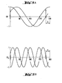
- Figs.SA to 5D are a series of illustrations showing the output torque produced by each pole of a pair of pole pieces where the normal displacement has been changed by "S" electrical degrees by shifting the stator pole position.
- Fig. 5A illustrates the effect on the fundamental and Figs. 5B, 5C and 5D illustrate the effect of this same shift on the third, fourth and fifth harmonics, respectively.
- one stator pole piece produces a torque which is in-phase as shown by the solid trace of Fig. 5A. If another pole piece is shifted by "S" electrical degrees from its normal position at 2 pi electrical degrees from the first pole piece, it produces a torque as shown in the dotted line.
- each pole piece in the motor can be individually calculated on-a per phase basis and the effect on the total motor torque can be determined by summing the indivudual pole piece contributions. If the pole pieces in each phase are similarly shifted in position, it is not necessary to calculate the actual total torque by vectorially summing the phase torques since calculation for a single phase provides the percentage torque reduction.
- the fundamental torque summation for a phase is in accordance with the following eauation: where S1, S 2 1 S 3 --- are the respective shift angles. From equation (1) it can be seen that the torque output is a vector summation taking into account the phase shift resulting from the individual shifts in the pole piece positions.
- the amount of harmonic suppression is likewise determined by vector summation. These summations for the harmonics can be divided by the number of poles and multiplied by 100 to determine the percentage of the harmonic remaining following suppression as compared to the magnitude of the harmonic existing in the motor with pole pieces in the normal position.
- Harmonic reduction is achieved where the components at the harmonic frequency tend to cancel one another. This can be achieved with respect to a pair of poles by shifting one 180 electrical-degrees for the particular harmonic being cancelled. Similarly, using three poles, if one pole is shifted +120 electrical degrees and another is shifted -120 electrical degrees, the harmonic contribution from the three poles cancels out. Similarly, harmonic cancellation can be achieved by appropriately shifting larger groups. The conflicting requirements for cancellation of the different harmonics makes it difficult or impossible to achieve perfect cancellation of all harmonics. However,-in designing a motor according to the invention, the design is facilitated by shifting the poles systematically toward the positions cancelling the harmonics.
- a two-phase construction tends to cancel out most of the second harmonic and normally harmonics above the fifth are not substantial.
- the 3rd, 4th and 5th harmonics need be considered as a practical matter.
- the value of a harmonic can be reduced to below 3% of the magnitude of the fundamental, the harmonic has no significant effect and can be considered virtually eliminated.
- the 3rd harmonic at 25%
- this harmonic would fall below 3% and is substantially eliminated.
- the 4th harmonic is reduced to 20% of the initial value, it is substantially eliminated.
- the 5th harmonic is reduced to 30% of the initial value, it, too, is substantially eliminated.
- the harmonics combined should be below 5% of magnitude of the fundamental.
- the approximate total harmonic distortion (THD) can be calculated using harmonic percentage values in the following equation for the main harmonics (i.e., 3rd, 4th and 5th): Since suppression of harmonics by shifting pole positions reduces the torque output of the motor, it is preferable to provide no more suppression than is required. In other words, the shift angles should be selected to provide the required suppression with a minimum reduction in the output torque at the fundamental frequency.
- the pole positions are shifted by the angles indicated in the column headed "shift" in Table I.
- the shift angles are in electrical degrees relative to the normal pole piece position.
- a positive shift angle is a clockwise shift, whereas a negative shift angle is a counter-clockwise shift.
- the real and imaginary components of the vectors for the fundamental are calculated in columns R1 and I1.
- the real components for the 3rd, 4th and 5th harmonics are calculated in columns R3, R4 and R5 whereas the imaginary components are calculated in columns I3, I4 and I5.
- the columns are summed and then squared.
- the squares are then summed and the square root taken to obtain the vector sum value. This value is then normalized by dividing by the number of poles.
- the 3rd harmonic is reduced to 5.08% of the initial value
- the 4th harmonic is reduced to 9.63% of the initial value
- the 5th harmonic is reduced to 2.25% of the initial value.
- the values of the 3rd, 4th and 5th harmonics are 25%, 15% and 10%, respectively, then the values would be 1.27%, 1.45% and 0.22% after suppression.
- the total harmonic distortion (THD) is 1.94%.
- the fundamental is only reduced to 82.92% of the initial value as a result of the pole shifting to achieve harmonic suppression.
- ten pole positions are shifted as indicated in Table II.
- This example is suitable for shifting the ten available pole positions, shown in Fig. 4.
- the harmonic suppression in this example is less than in Example 1, but still adequate to maintain each of the harmonics at less than 33% of the fundamental and the total harmonic distortion (THD) below 5%.
- the benefit of the reduced suppression is a higher fundamental at 85.01% of the initial value.
- the shift angles are as indicated in Table III.
- the harmonics are each suppressed to values below 0.4% of the fundamental (0.08%, 0.39% and 0.35%) and the THD is below 1% (0.53%).
- the fundamental is, however, reduced to 77.66% of the initial value.
- poles 2 and 4 are each shifted pi/5 (36°) electrical degrees relative to poles 1 and 3, respectively, to cancel the 5th harmonic,and poles 3 and 4 as a group are shifted pi/3 (60°) electrical degrees relative to poles 1 and 2 to cancel the 3rd harmonic.
- the resulting shift angles are 0, 36, 60 and 90 degrees as indicated in Table IV.
- the 3rd and 5th harmonics are cancelled, but the 4th harmonic is at 15.45% of the original value.
- the fundamental is at 82.36%.
- Stepping motor 100 includes two phase windings 102 and 104.
- the stepping position is controlled according to the digital count in a counter 106 which receives forward (FWD) and reverse (REV) pulses to cause the counter to count up and down.
- the digital output from counter 106 is supplied as an address input to a sine PROM (programmable read only memory) 107 and to a cosine PROM 117.
- the digital outputs from PROMs 107 and 117 are supplied to digital-to-analog (D/A) converters 108 and 118, respectively, which in turn supply analog input signals to power amplifiers 109 and 119, respectively.
- D/A digital-to-analog
- Amplifier 109 supplies energizing current to motor winding 102
- drive amplifier 119 similarly provides energizing current to motor winding 104.
- the drive amplifiers 109 and 119 are preferably of the chopper or pulse width modulated type.
- the sine and cosine values are converted to corresponding analog signal values by converters 108 and 118, and currents proportional to these analog values are supplied to the motor by drive amplifiers 109 and 119.
- the sine and cosine values can be used in PROMs 107 and 117 to accurately control micropositioning of the motor only if there are no substantial harmonics in the motor torque displacement characteristic.
- the microstepping motor according to the invention is constructed to suppress significant harmonics and, therefore, accurate microstep positioning can be achieved by using sine wave quadrature proportioning in the drive signals.
- the positioning accuracy can be further improved by adjustung the proportioned values stored in the PROMs to more exactly correspond to the torque displacement characteristic of the motor. Since the significant motor harmonics are suppressed in the stepping motor according to the invention, the deviation from the ideal sinusoidal proportioned signals is small and, therefore, effective improvement in the accuracy can be achieved over a broad torque and speed range.
- FIG. 7 Another embodiment of the drive circuitry for motor 100 is shown in Fig. 7 wherein a microprocessor is used to calculate the proportioned drive signals.
- Microprocessor 120 receives a digital indication of the desired microstep angular position alpha ( ⁇ ) and produces digital values for sine oC. and cosine ⁇ at the two output ports.
- the digital output indications of the microprocessor 120 are supplied to latches 122 and 132, respectively, to hold the digital indications during subsequent calculations by the microprocessor 120.
- the digital output of latch circuit 122 is converted to a corresponding analog signal by D/A converter 124 and the analog signal is converted to a corresponding drive current supplied to motor winding 102 by drive amplifier 126.
- the digital output from latch circuit 132 is, in turn, converted to a corresponding analog signal by D/A converter 134 and the analog signal, in turn, is converted to a drive current for winding 104 by drive amplifier 136.
- the microprocessor can be programmed to calculate sine and cosine values, a faster and simpler approach is to obtain the values from a look-up table stored in the microprocessor memory. The use of a look-up table also permits adjustment of the proportioned values to the actual torque/displacement characteristic of the motor.
Landscapes
- Engineering & Computer Science (AREA)
- Power Engineering (AREA)
- Control Of Stepping Motors (AREA)
- Iron Core Of Rotating Electric Machines (AREA)
Applications Claiming Priority (2)
| Application Number | Priority Date | Filing Date | Title |
|---|---|---|---|
| US817677 | 1986-04-17 | ||
| US06/817,677 US4703243A (en) | 1986-04-17 | 1986-04-17 | Stepping motor harmonic suppression |
Publications (2)
| Publication Number | Publication Date |
|---|---|
| EP0242673A2 true EP0242673A2 (de) | 1987-10-28 |
| EP0242673A3 EP0242673A3 (de) | 1988-03-23 |
Family
ID=25223621
Family Applications (1)
| Application Number | Title | Priority Date | Filing Date |
|---|---|---|---|
| EP87104981A Withdrawn EP0242673A3 (de) | 1986-04-17 | 1987-04-03 | Unterdrückung der Oberschwingungen in einem Mikroschrittmotor |
Country Status (4)
| Country | Link |
|---|---|
| US (1) | US4703243A (de) |
| EP (1) | EP0242673A3 (de) |
| DE (1) | DE3713148A1 (de) |
| GB (1) | GB2189358B (de) |
Cited By (2)
| Publication number | Priority date | Publication date | Assignee | Title |
|---|---|---|---|---|
| EP0319632A1 (de) * | 1987-12-10 | 1989-06-14 | Portescap | Elektrischer Motor mit einem vielpoligen Dauermagnetläufer |
| WO2006064089A1 (en) * | 2004-12-13 | 2006-06-22 | Kone Corporation | Reduction of harmonics in an electric motor |
Families Citing this family (21)
| Publication number | Priority date | Publication date | Assignee | Title |
|---|---|---|---|---|
| US4980617A (en) * | 1988-02-24 | 1990-12-25 | Hitachi, Ltd. | Speed control apparatus of movable equipment |
| DE3836531A1 (de) * | 1988-10-27 | 1990-05-03 | Telefunken Electronic Gmbh | Schrittmotorsteuerung |
| US5229677A (en) * | 1991-09-18 | 1993-07-20 | Newport News Shipbuilding And Dry Dock Company | Electric propulsion motor for marine vehicles |
| US5264770A (en) * | 1992-03-12 | 1993-11-23 | Coutu David J | Stepper motor driver circuit |
| US5225756A (en) * | 1992-03-26 | 1993-07-06 | David J. Coutu | Stepper motor driver circuit |
| DE69636505T2 (de) * | 1995-06-07 | 2007-05-24 | General Electric Co. | Dynamoelektrische Maschine und deren Rotorkonstruktion |
| US6100620A (en) * | 1996-08-05 | 2000-08-08 | S.H.R. Ltd. Bvi | High frequency synchronous rotary electrical machine |
| CN1149731C (zh) | 1998-03-26 | 2004-05-12 | 精工爱普生株式会社 | 步进电机、使用它的打印装置、送纸装置及打印机 |
| US6013998A (en) * | 1998-07-29 | 2000-01-11 | Eastman Kodak Company | Method for compensating for positional error inherent to stepper motors running in microstepping mode |
| US6064170A (en) * | 1998-08-31 | 2000-05-16 | Eastman Kodak Company | Method of controlling a printhead movement based on a screw pitch to minimize swath-to-swath error in an image processing apparatus |
| US6049348A (en) * | 1998-08-31 | 2000-04-11 | Eastman Kodak Company | Programmable gearing control of a leadscrew for a printhead having a variable number of channels |
| US6140793A (en) * | 1999-08-19 | 2000-10-31 | Bristol-Myers Squibb Company | Stepper motor controller for microstepping a stepper motor and a method for microstepping a stepper motor |
| US6611072B1 (en) | 1999-11-17 | 2003-08-26 | Parker-Hannifin Corporation | Sensorless stall detection for motors |
| DE10062073A1 (de) * | 2000-12-13 | 2002-06-20 | Bosch Gmbh Robert | Unipolar-Transversalflußmaschine |
| DE10140303A1 (de) * | 2001-08-16 | 2003-02-27 | Bosch Gmbh Robert | Unipolar-Transversalflußmaschine |
| TW570266U (en) * | 2002-10-22 | 2004-01-01 | Delta Electronics Inc | Guiding structure without eccentricity |
| TWI241568B (en) * | 2004-02-10 | 2005-10-11 | Delta Electronics Inc | Guiding mechanism |
| US7518270B2 (en) * | 2005-07-15 | 2009-04-14 | Lin Engineering, Inc. | Accurate microstepping motor |
| US20080169731A1 (en) * | 2007-01-11 | 2008-07-17 | Lin Ted T | Rotor for hybrid step motor with smooth motion |
| US7847579B2 (en) * | 2007-06-28 | 2010-12-07 | Gm Global Technology Operations, Inc. | Systems and methods to evaluate permanent magnet motors |
| CN103023256B (zh) * | 2011-09-26 | 2017-03-01 | 辐射通量实验室私人有限公司 | 永磁电机 |
Citations (3)
| Publication number | Priority date | Publication date | Assignee | Title |
|---|---|---|---|---|
| FR2363928A1 (fr) * | 1976-09-03 | 1978-03-31 | Portescap | Moteur pas a pas multipolaire a rotor aimante |
| US4377847A (en) * | 1981-02-17 | 1983-03-22 | Gould Inc. | Microprocessor controlled micro-stepping chart drive |
| US4516048A (en) * | 1983-09-29 | 1985-05-07 | The Superior Electric Company | Stator with nonuniformly spaced teeth for rotating electromagnetic device |
Family Cites Families (4)
| Publication number | Priority date | Publication date | Assignee | Title |
|---|---|---|---|---|
| US4091316A (en) * | 1975-09-30 | 1978-05-23 | The Computervision Corporation | Method and apparatus for damping stepper motors |
| DE2834740A1 (de) * | 1978-08-08 | 1980-02-21 | Franz Vertriebs Gmbh | Antriebsanordnung fuer ein informationsspeicherlaufwerk insbesondere fuer einen plattenspieler |
| US4297625A (en) * | 1979-04-09 | 1981-10-27 | Mesur-Matic Electronics Corporation | Apparatus for dividing the step angle of a stepping motor |
| CH653189A5 (fr) * | 1983-04-08 | 1985-12-13 | Portescap | Moteur pas a pas electrique. |
-
1986
- 1986-04-17 US US06/817,677 patent/US4703243A/en not_active Expired - Fee Related
-
1987
- 1987-04-03 EP EP87104981A patent/EP0242673A3/de not_active Withdrawn
- 1987-04-07 GB GB8708228A patent/GB2189358B/en not_active Expired
- 1987-04-14 DE DE19873713148 patent/DE3713148A1/de not_active Ceased
Patent Citations (4)
| Publication number | Priority date | Publication date | Assignee | Title |
|---|---|---|---|---|
| FR2363928A1 (fr) * | 1976-09-03 | 1978-03-31 | Portescap | Moteur pas a pas multipolaire a rotor aimante |
| US4377847A (en) * | 1981-02-17 | 1983-03-22 | Gould Inc. | Microprocessor controlled micro-stepping chart drive |
| US4377847B1 (de) * | 1981-02-17 | 1985-05-28 | ||
| US4516048A (en) * | 1983-09-29 | 1985-05-07 | The Superior Electric Company | Stator with nonuniformly spaced teeth for rotating electromagnetic device |
Cited By (4)
| Publication number | Priority date | Publication date | Assignee | Title |
|---|---|---|---|---|
| EP0319632A1 (de) * | 1987-12-10 | 1989-06-14 | Portescap | Elektrischer Motor mit einem vielpoligen Dauermagnetläufer |
| WO2006064089A1 (en) * | 2004-12-13 | 2006-06-22 | Kone Corporation | Reduction of harmonics in an electric motor |
| US7675213B2 (en) | 2004-12-13 | 2010-03-09 | Kone Corporation | Reduction of harmonics in an electric motor |
| CN101116233B (zh) * | 2004-12-13 | 2010-09-08 | 通力股份公司 | 减小电机中的谐波 |
Also Published As
| Publication number | Publication date |
|---|---|
| GB2189358B (en) | 1989-11-29 |
| EP0242673A3 (de) | 1988-03-23 |
| DE3713148A1 (de) | 1987-10-29 |
| GB8708228D0 (en) | 1987-05-13 |
| GB2189358A (en) | 1987-10-21 |
| US4703243A (en) | 1987-10-27 |
Similar Documents
| Publication | Publication Date | Title |
|---|---|---|
| EP0242673A2 (de) | Unterdrückung der Oberschwingungen in einem Mikroschrittmotor | |
| US4629916A (en) | Method and apparatus for harmonics suppression in motor systems | |
| EP0096390B1 (de) | Motor mit hohem Drehmoment für Roboter | |
| US5128570A (en) | Permanent magnet type stepping motor | |
| US5374865A (en) | Multi-phase hybrid stepper motor | |
| EP0837544B1 (de) | Motorzusammensetzung | |
| CA1292767C (en) | Polyphase dc motor with sensor poles | |
| US4424463A (en) | Apparatus for minimizing magnetic cogging in an electrical machine | |
| JP3051340B2 (ja) | 同期電動機 | |
| US7425785B2 (en) | Permanent magnet motor | |
| US4983867A (en) | Hybrid-type stepping motor | |
| US5168187A (en) | Axial pole stepping motor | |
| US4517478A (en) | Electric stepper motor | |
| GB2220529A (en) | Reducing detent torque in multipole d.c. electric motors | |
| EP0230605A1 (de) | Schrittmotor | |
| JPS61203862A (ja) | ステツプ・モ−タ | |
| EP0308577A2 (de) | Zwölf-Schritt-Kommutierungsvorrichtung für einen Elektromotor | |
| US4006375A (en) | Stepping motor | |
| KR19990077339A (ko) | 엑시얼 폴 모터 | |
| EP0645876B1 (de) | Linearer Schrittmotor | |
| EP2324563B1 (de) | Schrittmotoren des permanentmagnettyps | |
| US4792709A (en) | Winding for operation of a three-phase stepping motor from a two-phase drive | |
| US4488069A (en) | Stepping motor | |
| JPH06245466A (ja) | 多相ハイブリッド型ステッピングモータの駆動方法 | |
| JPS634414B2 (de) |
Legal Events
| Date | Code | Title | Description |
|---|---|---|---|
| PUAI | Public reference made under article 153(3) epc to a published international application that has entered the european phase |
Free format text: ORIGINAL CODE: 0009012 |
|
| AK | Designated contracting states |
Kind code of ref document: A2 Designated state(s): CH DE FR LI NL |
|
| PUAL | Search report despatched |
Free format text: ORIGINAL CODE: 0009013 |
|
| AK | Designated contracting states |
Kind code of ref document: A3 Designated state(s): CH DE FR LI NL |
|
| 17P | Request for examination filed |
Effective date: 19880919 |
|
| STAA | Information on the status of an ep patent application or granted ep patent |
Free format text: STATUS: THE APPLICATION IS DEEMED TO BE WITHDRAWN |
|
| 18D | Application deemed to be withdrawn |
Effective date: 19891103 |
|
| RIN1 | Information on inventor provided before grant (corrected) |
Inventor name: ETTELMAN, DAVID J. Inventor name: FLORESTA, JOHN G. |