EP0242606A2 - Kappe für Sprühdose - Google Patents
Kappe für Sprühdose Download PDFInfo
- Publication number
- EP0242606A2 EP0242606A2 EP87104128A EP87104128A EP0242606A2 EP 0242606 A2 EP0242606 A2 EP 0242606A2 EP 87104128 A EP87104128 A EP 87104128A EP 87104128 A EP87104128 A EP 87104128A EP 0242606 A2 EP0242606 A2 EP 0242606A2
- Authority
- EP
- European Patent Office
- Prior art keywords
- closure
- passages
- orifice
- annular
- passage
- Prior art date
- Legal status (The legal status is an assumption and is not a legal conclusion. Google has not performed a legal analysis and makes no representation as to the accuracy of the status listed.)
- Withdrawn
Links
Images
Classifications
-
- B—PERFORMING OPERATIONS; TRANSPORTING
- B05—SPRAYING OR ATOMISING IN GENERAL; APPLYING FLUENT MATERIALS TO SURFACES, IN GENERAL
- B05B—SPRAYING APPARATUS; ATOMISING APPARATUS; NOZZLES
- B05B9/00—Spraying apparatus for discharge of liquids or other fluent material, without essentially mixing with gas or vapour
-
- B—PERFORMING OPERATIONS; TRANSPORTING
- B05—SPRAYING OR ATOMISING IN GENERAL; APPLYING FLUENT MATERIALS TO SURFACES, IN GENERAL
- B05B—SPRAYING APPARATUS; ATOMISING APPARATUS; NOZZLES
- B05B11/00—Single-unit hand-held apparatus in which flow of contents is produced by the muscular force of the operator at the moment of use
- B05B11/01—Single-unit hand-held apparatus in which flow of contents is produced by the muscular force of the operator at the moment of use characterised by the means producing the flow
- B05B11/04—Deformable containers producing the flow, e.g. squeeze bottles
- B05B11/042—Deformable containers producing the flow, e.g. squeeze bottles the spray being effected by a gas or vapour flow in the nozzle, spray head, outlet or dip tube
- B05B11/043—Deformable containers producing the flow, e.g. squeeze bottles the spray being effected by a gas or vapour flow in the nozzle, spray head, outlet or dip tube designed for spraying a liquid
-
- B—PERFORMING OPERATIONS; TRANSPORTING
- B05—SPRAYING OR ATOMISING IN GENERAL; APPLYING FLUENT MATERIALS TO SURFACES, IN GENERAL
- B05B—SPRAYING APPARATUS; ATOMISING APPARATUS; NOZZLES
- B05B11/00—Single-unit hand-held apparatus in which flow of contents is produced by the muscular force of the operator at the moment of use
- B05B11/0005—Components or details
- B05B11/0027—Means for neutralising the actuation of the sprayer ; Means for preventing access to the sprayer actuation means
- B05B11/0029—Valves not actuated by pressure
Definitions
- This invention relates to a push/pull spray cap assembly. More particularly, the invention relates to a spray cap assembly for a container made of a resilient material having a base unit including a dispensing duct in communication with an air passage and a material passage, and an insertable push/pull closure mated to fit into the base unit which permits the sealing of the air and material passages from the dispensing duct and from each other.
- the assembly by modifying the design of the dispensing duct permits the dispensing of a variety of products having varying consistencies contained in the resilient container as a spray or mist by exertion of pressure on the walls of the container, such as by squeezing the container in the hand of the user.
- Squeeze bottles i.e., bottles made of a resilient material which can have the contents thereof discharged by external pressure exerted on the walls of the bottle, have been used for a long time primarily due to convenience and cost. More recently these squeeze dispensers have become increasingly attractive for the dispensing of various products as sprays or mists due at least in part to the ecological problems encountered with aerosols, or due to cost or flammability problems associated with aerosols designed to overcome the ecological problems.
- spray squeeze bottle dispensers have utilized a variety of closures including a push/pull closure assembly with separate air and fluid passages.
- the push/pull closures disclosed are mounted within a neck of a squeeze bottle; and, in order to prevent fluid material from being dispensed when not in use, the entire push/pull closure assembly is pushed into the neck of the bottle.
- U.S. Patent No. 3,330,446 discloses a push/pull spray head for a squeeze bottle dispenser having separate air and fluid material passages therein.
- the air and fluid material passages each enter a discharge duct wherein the air joins with the fluid material and are expelled simultaneously through a discharge orifice in the form of a spray.
- the dispenser is closed by pushing the entire spray head assembly into the neck of the squeeze bottle.
- U.S. Patent No. 3,255,934 discloses a push/pull spray assembly fitted inside the neck of a squeeze bottle. Separate air and material passages are formed in the body of the push/pull assembly. Each passage enters a discharge duct prior to exiting a discharge orifice at the end of the duct as a spray.
- U.S. Patent No. 2,961,169 discloses a closure for a squeeze container which fits within the neck of the container.
- the closure is a pluglike member having a slot formed therein so that air can move from the interior of the container into a discharge duct.
- the air combines with and is discharged with fluid material entering the discharge duct by a separate passage formed in the pluglike member.
- the fluid material and air are discharged as a spray.
- the container is closed by pushing the pluglike member inside the neck of the container.
- the orifice in these assemblies, while adjoining, function primarily as a vapor tap and cause or permit only limited mixing of the product and air at the time of spraying and, accordingly, the break-up of the product into a fine aerosol like spray is not realized.
- Squeeze bottle dispensers utilizing a swirl chamber insert with separate fluid material and air passages located inside the spray head are also known.
- the material and air passages abut and have openings into a channel formed by a swirl chamber insert.
- U.S. Patent No. 4,157,789 discloses a right angle spray nozzle having a swirl chamber insert with a fluid material passage and air passage in communication with a discharge duct and outlet formed by the swirl chamber insert.
- the manner of closing the discharge orifice is by rotating a wall-containing member in front of the discharge orifice.
- U.S. Patent No. 4,020,979 also discloses a squeeze bottle spray dispenser utilizing a swirl chamber insert.
- a material passage which flows through a post in the swirl chamber and an air passage are in communication with a discharge duct formed by the swirl chamber insert.
- the fluid material and air exit together through the discharge orifice in the form of a spray.
- These dispenser assemblies do not provide a means of sealing the fluid material and air passages.
- the closure means disclosed is the rotation of a wall-containing member in front of the discharge orifice.
- the assemblies are relatively complex and, accordingly, are relatively costly and leave room for malfunctioning, including by plugging.
- Squeeze bottle dispensers having a fluid material passage and an air passage formed in the outlet wall of a dispenser with the fluid material and air passage being closed by a flip cap having two downwardly extending posts which fit into the fluid material and air passages simultaneously to seal the passages are disclosed in U.S. Patent Nos. 2,991,913 and 3,724,723.
- the present invention seeks to provide a push/pull closure assembly for a container composed of a resilient material which permits the dispensing of a variety of products having varying consistencies contained in the resilient container as a spray by exertion of external pressure on the container, such as by squeezing the container in the hand of the user.
- this invention provides a closure assembly for a container of a resilient material composed of a base unit including a dispensing orifice in communication with a material passage and an air passage, and an insertable push/pull closure interfitted to the base unit for closing off the material and air passages and separating the air passage from the material passage.
- the present invention provides a spray cap assembly for attachment to a resilient container comprising a base unit including a skirt portion for attachment to a resilient container, an annular sidewall portion positioned above said skirt portion integral therewith, a discharge chamber recessed into said sidewall portion, an orifice in said discharge chamber extending through said annular sidewall portion, a separation wall within said annular sidewall portion and extending at right angles to said annular sidewall, first and second parallel tubular passages extending through said separation wall, the first of said passages having an opening therein to place said passage in communication with said orifice and the second of said passages having an opening therein to place said passage in communication with said discharge chamber; an insert in said discharge chamber having a dispensing opening to form a product-air mixing chamber behind said insert, said opening being in communication with said orifice and with the opening in the second passage; a push/pull closure comprising a closed end, an annular closure sidewall extending downwardly from said closed end, said annular closure
- the spray cap assembly of the present invention is of simple construction, attractive, and provides for the construction of a squeeze bottle for dispensing products of varying consistency simply by modifying the discharge duct, preferably by use of an insert in the orifice so as to provide a swirl chamber. Moreover, the spray cap provides a good seal when not in use, avoiding loss of product by leakage or evaporation. The spray cap is easy for the ultimate consumer to use.
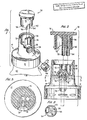
- the spray cap assembly is composed of a base unit 10 and a push/pull closure 30.
- the base unit 10 designed to be attached to the neck of a squeeze bottle, includes a skirt portion 12 for releasable attachment to a squeeze bottle 40.
- the skirt portion 12 of base unit 10 fits over and snaps onto neck 42 of the squeeze container 40 by means of cooperating indents 44 in neck 42 and protrusions 14 in skirt portion 12.
- An annular sidewall portion 16 of smaller diameter than skirt portion 12 is integral with and extends above skirt portion 12.
- Annular sidewall portion 16 has a discharge orifice chamber 20 recessed into annular sidewall portion 16 surrounding an orifice 18.
- Chamber 20 is in communication with first and second adjacent tubular passages 22 and 24 through openings 23 and 25, respectively, in the passage walls.
- passage 22 is in communication through a dip tube 46 with the interior of the squeeze bottle 40 and with the external atmosphere through passage wall opening 23, chamber 20, and orifice 18.
- Passage 24 which is an air passage, extends above separating wall 26 and terminates at, or substantially at wall 26 and is in gaseous communication with the interior of squeeze bottle 40 and with the atmosphere through passage wall opening 25 and chamber 20. Passages 22 and 24 are disposed in parallel relation
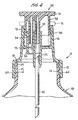
- the spray cap assembly is provided with a push/pull closure 30 which controls the ability of the fluid material and air to enter the orifice chamber 20.
- Pushpull closure 30 comprises a flat end 31 and integral therewith a downwardly extending annular closure sidewall 33.
- the flat end 31 preferably has a larger circumference than the annular skirt 12 of the base unit 16 to permit a user to pull the closure 30 upward when the closure 30 is positioned in the base unit 16.
- the closure 30 has two adjacent and parallel posts 32, 34 which may either be hollow or solid integral with the inside of the flat end 31 which extend downwardly into and beyond the bottom edge of the annular skirt 12 of the base unit 16.
- the closure 30 is mated to fit inside the inner circumference of the base unit 16, with the two posts 32, 34 fitting inside the two tubular passages 22, 24 of the base unit 16.
- the sidewall 33 of the closure 30 is cut away as at 37 to provide a clearance for orifice chamber 20.
- Projection 36 are located on the exterior of annular sidewall 33 of closure 30 which operate in conjunction with a shoulder 29 formed in the inside of the annular sidewall portion 16 of the base unit 10 to prevent the closure 30 from being removed from the base unit 10 when pulled upward.
- the position of, and the length of the two downwardly extending posts 32, 34 is such that the posts 32, 34 will mate with and remain seated within but at the top of the two passages 22, 24 of the base unit 10 when the closure 30 is pulled upward as shown in Fig.
- push/pull closure 30 is inserted into base unit 10, and base unit 10 containing dip tube 46 is attached to squeeze bottle 40. If a larger diameter dip tube 46 is used, it can fit over the outside of passage 22. The attachment of base unit 10 to bottle 40 must form a seal. If rim 62 of bottle 40 is sufficiently flat to form an airtight seat with shoulder 64 of base unit 10, no additional sealing is required. However, if rim 62 has any irregularities, it may be advisable to use a gasket (not shown) or other means to provide a complete seal between bottle 40 and base unit 10. When closure 30 is in the up or open position as shown in solid lines in Fig. 4, post units 32 and 34 are retained in parallel passages 22 and 24.
- passages 22 and 24 are in communication through passage 23 and opening 25 with chamber 20 and orifice 18.
- material within the container 40 passes up dip tube 46 through passage 22 and passage 23, and out orifice 18.
- air passes through passage 24 and through opening 25 in the wall of passage 24 into chamber 20.
- the air forced into the discharge orifice 18 provides for a smooth flow of the fluid material from the dispenser; mixes with the material being dispensed, thus aiding in the formation of a spray of the dispensed material; and provides an air inlet for reinflating the squeeze bottle 40.
- the dispenser has means to aid in the formation of a spray.
- the diameter of passage 23 increases gradually along the length of passage 23 from an internal orifice 17 to the orifice 18. This slows the velocity of the liquid being dispensed from bottle 40 and aids in breaking up the liquid to produce a fine spray.
- the air intimately mixes with and breaks up the product to provide a fine spray or mist.
- the vacuum created draws air through opening 56, through ribs 58, through opening 25, and through second passage 24 into the interior of bottle 40. Also, some air is simultaneously drawn through passage 23, passage 22, and dip tube 46.
- push/pull closure 30 is pressed down as shown in phantom lines in Fig. 4.
- posts 32 and 34 block and seal passages 22 and 24 at, or substantially at the level of separating wall 26.
- the push/pull closure permits the opening and closing of the parallel air and material passages with a simple movement while providing a tight seal.
- a cup-shaped swirl insert 50 shown in Figs. 1 and 5 is placed in the orifice chamber 20 to form an annular passage to improve the spraying capabilities of the dispenser.
- the insert comprises annular wall 52 and wall 54 at right angles to the annular wall 52 having an opening 56.
- a series of depressed ribs 58 are positioned on wall 54 inside of wall 52 to provide a break-up of product being sprayed and mixing of the product with air to provide the desired spray pattern.
- the spray cap can be modified to dispense a wide variety of liquids having different viscosities. Three of the elements which affect the spray pattern are the diameter of dip tube 46, the diameter of orifices 18 and 17, and the diameter of orifice 56. Other openings can be modified in addition to the above, however these have the greatest impact on the spray pattern.
Landscapes
- Closures For Containers (AREA)
- Containers And Packaging Bodies Having A Special Means To Remove Contents (AREA)
Applications Claiming Priority (2)
| Application Number | Priority Date | Filing Date | Title |
|---|---|---|---|
| US06/842,969 US4711378A (en) | 1986-03-24 | 1986-03-24 | Spray cap assembly comprising a base unit and push/pull closure means |
| US842969 | 1986-03-24 |
Publications (2)
| Publication Number | Publication Date |
|---|---|
| EP0242606A2 true EP0242606A2 (de) | 1987-10-28 |
| EP0242606A3 EP0242606A3 (de) | 1988-10-05 |
Family
ID=25288718
Family Applications (1)
| Application Number | Title | Priority Date | Filing Date |
|---|---|---|---|
| EP87104128A Withdrawn EP0242606A3 (de) | 1986-03-24 | 1987-03-20 | Kappe für Sprühdose |
Country Status (9)
| Country | Link |
|---|---|
| US (1) | US4711378A (de) |
| EP (1) | EP0242606A3 (de) |
| JP (1) | JPS62269768A (de) |
| KR (1) | KR870008626A (de) |
| AU (1) | AU588093B2 (de) |
| BR (1) | BR8701304A (de) |
| NZ (1) | NZ219738A (de) |
| PH (1) | PH22788A (de) |
| PT (1) | PT84550A (de) |
Families Citing this family (12)
| Publication number | Priority date | Publication date | Assignee | Title |
|---|---|---|---|---|
| JPH0536529Y2 (de) * | 1988-04-26 | 1993-09-16 | ||
| USD335175S (en) | 1990-10-15 | 1993-04-27 | Sladek David T | Combined ventilator dispenser and adapter |
| AU638927B3 (en) * | 1992-02-17 | 1993-07-08 | Graeme V. Landy | Safety drinking cap |
| AU661549B2 (en) * | 1992-02-17 | 1995-07-27 | Graeme Landy | Safety drinking cap |
| US6398133B1 (en) | 1999-12-22 | 2002-06-04 | Emsar, Inc. | Dispensing head for a squeeze dispenser |
| US8074649B2 (en) | 2002-07-18 | 2011-12-13 | Aeon Research And Technology, Inc. | Endotracheal tube with feature for delivering aerosolized medication |
| FR2856985B1 (fr) * | 2003-07-02 | 2006-06-09 | Seaquist General Plastics | Tete de distribution de produit fluide et utilisation d'une telle tete |
| US8657794B2 (en) * | 2009-10-08 | 2014-02-25 | Skylab Development, Inc. | High flow volume nasal irrigation device and method for alternating pulsatile and continuous fluid flow |
| US8746511B2 (en) * | 2011-10-05 | 2014-06-10 | The Boeing Company | Self-sealing dispenser insert and method for assembling the same |
| US9498592B2 (en) | 2012-01-23 | 2016-11-22 | Aeon Research And Technology, Inc. | Modular pulmonary treatment system |
| US8998033B2 (en) * | 2012-04-19 | 2015-04-07 | Paul Maurice HUARD | Material dispenser |
| FR3071752B1 (fr) | 2017-10-02 | 2022-07-22 | Oreal | Capsule a ouverture par traction equipee d’une reprise d’air |
Family Cites Families (42)
| Publication number | Priority date | Publication date | Assignee | Title |
|---|---|---|---|---|
| US1716525A (en) * | 1928-11-12 | 1929-06-11 | Silvestre V Leong | Spraying or atomizing device |
| US2112125A (en) * | 1934-09-24 | 1938-03-22 | Bultzingslowen Bruno Von | Closure |
| US2179423A (en) * | 1938-09-28 | 1939-11-07 | Pari Jack | Closure device for collapsible tubes and the like |
| US2531745A (en) * | 1947-11-18 | 1950-11-28 | Clifford S Schopmeyer | Squeeze-bottle atomizer for acid liquids |
| US2649334A (en) * | 1949-08-24 | 1953-08-18 | Jules Schneider | Atomizer |
| US2808966A (en) * | 1954-04-13 | 1957-10-08 | Joseph B Biederman | Dispensing pump and valve arrangement |
| US2790582A (en) * | 1954-12-20 | 1957-04-30 | Halpern Israel Alfred | Pouring spout |
| BE561228A (de) * | 1956-10-01 | E Robert Fred Vauthier & Cie Ets | ||
| US2991913A (en) * | 1957-01-18 | 1961-07-11 | Goth Imre | Combined pouring and sealing devices for containers |
| US2877918A (en) * | 1957-05-06 | 1959-03-17 | Leonal P Gardner | Snap cap for bottles |
| US2931543A (en) * | 1958-07-03 | 1960-04-05 | Edward L Thomas | Collapsible tube closure |
| US2961169A (en) * | 1958-09-09 | 1960-11-22 | Nyden Robert | Valved closures for containers |
| US3085721A (en) * | 1959-03-17 | 1963-04-16 | Schenley Ind Inc | Bottle closure and pourer |
| US3122285A (en) * | 1960-11-21 | 1964-02-25 | Pluess Otto | Fluid dispensing device |
| NL281619A (de) * | 1961-11-11 | |||
| US3255933A (en) * | 1964-04-06 | 1966-06-14 | Kilburn Chemical Company | Dispensing container with bellows |
| US3255934A (en) * | 1964-04-07 | 1966-06-14 | Eskimo Pie Corp | Squeeze-spray dispensing package |
| DE1475167A1 (de) * | 1964-09-24 | 1969-02-20 | Werner & Mertz Gmbh | Spruehkopf fuer elastische Kunststoff-Flaschen |
| FR1418921A (fr) * | 1964-10-12 | 1965-11-26 | Perfectionnement apporté aux têtes de vaporisation | |
| US3276641A (en) * | 1964-10-23 | 1966-10-04 | Valve Corp Of America | Actuator for dispensing pump |
| SE316128B (de) * | 1965-07-23 | 1969-10-13 | Ind Cervello Sa | |
| US3409182A (en) * | 1966-11-08 | 1968-11-05 | Lehmann Kenneth G | Squeeze bottle dispenser |
| US3392886A (en) * | 1967-01-16 | 1968-07-16 | Albert | Valve for liquid containers |
| US3474936A (en) * | 1967-05-29 | 1969-10-28 | John E Mcdonnell | Squeeze bottle dispenser |
| US3606107A (en) * | 1969-09-05 | 1971-09-20 | Inventions Unlimited Inc | Push-pull container and cap assembly |
| US3705668A (en) * | 1969-11-14 | 1972-12-12 | Gilbert Schwartzman | Dispenser with dip tube |
| US3724723A (en) * | 1970-07-24 | 1973-04-03 | A Slavinski | Spray devices for hair lacquer |
| US3794247A (en) * | 1972-11-22 | 1974-02-26 | Corsette Douglas Frank | Spray fitment for squeeze bottles |
| US3874563A (en) * | 1973-06-19 | 1975-04-01 | Gilbert Schwartzman | Applicator having multiple valve assemblies |
| US3987938A (en) * | 1975-09-18 | 1976-10-26 | Diamond International Corporation | Dispensing pump |
| US4020979A (en) * | 1975-10-15 | 1977-05-03 | Summit Packaging Systems, Inc. | Squeeze-bottle-type spray dispenser |
| US4122979A (en) * | 1976-06-01 | 1978-10-31 | Laauwe Robert H | Squeeze bottle containing a liquid product and operative whether upright or inverted |
| US4074861A (en) * | 1976-06-18 | 1978-02-21 | Realex Corporation | Spray pattern control structure and method |
| US4157789A (en) * | 1977-11-10 | 1979-06-12 | Laauwe Robert H | Right-angle spray nozzle |
| US4162749A (en) * | 1978-02-27 | 1979-07-31 | Risdon Manufacturing Company | Squeezable dispenser with outlet closure |
| US4239132A (en) * | 1978-10-31 | 1980-12-16 | Containaire, Inc. | Apparatus for facilitating inflow through closure threads of dispenser |
| US4420100A (en) * | 1978-10-31 | 1983-12-13 | Containaire, Inc. | Dispensing apparatus |
| US4223842A (en) * | 1978-12-04 | 1980-09-23 | Ethyl Corporation | Squeeze bottle atomizer |
| US4226367A (en) * | 1978-12-11 | 1980-10-07 | Ethyl Corporation | Squeeze bottle dispenser |
| US4340157A (en) * | 1980-11-20 | 1982-07-20 | Becton, Dickinson & Company | Self-sealing closure dispenser for plastic stain bottles |
| US4415122A (en) * | 1981-07-14 | 1983-11-15 | Essex Chemical Corporation | Right-angle spray nozzle |
| DE8621135U1 (de) * | 1985-09-02 | 1987-01-29 | Callahan, George Edgar, Prof., 40479 Düsseldorf | Sprühvorrichtung zum Aufsetzen auf einen zusammenpressbaren Behälter |
-
1986
- 1986-03-24 US US06/842,969 patent/US4711378A/en not_active Expired - Fee Related
-
1987
- 1987-03-18 PH PH35041A patent/PH22788A/en unknown
- 1987-03-20 EP EP87104128A patent/EP0242606A3/de not_active Withdrawn
- 1987-03-23 BR BR8701304A patent/BR8701304A/pt unknown
- 1987-03-23 AU AU70494/87A patent/AU588093B2/en not_active Ceased
- 1987-03-23 NZ NZ219738A patent/NZ219738A/xx unknown
- 1987-03-24 JP JP62068154A patent/JPS62269768A/ja active Pending
- 1987-03-24 KR KR870002679A patent/KR870008626A/ko not_active Withdrawn
- 1987-03-24 PT PT84550A patent/PT84550A/pt unknown
Also Published As
| Publication number | Publication date |
|---|---|
| NZ219738A (en) | 1990-06-26 |
| JPS62269768A (ja) | 1987-11-24 |
| BR8701304A (pt) | 1987-12-29 |
| PT84550A (en) | 1987-04-01 |
| PH22788A (en) | 1988-12-12 |
| EP0242606A3 (de) | 1988-10-05 |
| KR870008626A (ko) | 1987-10-19 |
| AU7049487A (en) | 1987-10-01 |
| US4711378A (en) | 1987-12-08 |
| AU588093B2 (en) | 1989-09-07 |
Similar Documents
| Publication | Publication Date | Title |
|---|---|---|
| US6394364B1 (en) | Aerosol spray dispenser | |
| US5938082A (en) | Container assembly having snap-fit container connection | |
| US20120091229A1 (en) | Manual pump type fluid dispenser | |
| US4711378A (en) | Spray cap assembly comprising a base unit and push/pull closure means | |
| US4773570A (en) | Discharge device for a deformable container | |
| AU775370B2 (en) | Dispensing head for a squeeze dispenser | |
| EP0238494B1 (de) | Flüssigkeitsbehälter | |
| EP1230984B1 (de) | Luftloser Sprühkopf für eine Drückflasche | |
| US6250568B1 (en) | Squeeze bottle aspirator | |
| KR20020087075A (ko) | 압착배출기용 배출헤드를 이용하는 방법 | |
| US11807445B2 (en) | Dispensing pump and manufacturing method thereof | |
| MXPA03001154A (es) | Distribuidor de botella comprimible. |
Legal Events
| Date | Code | Title | Description |
|---|---|---|---|
| PUAI | Public reference made under article 153(3) epc to a published international application that has entered the european phase |
Free format text: ORIGINAL CODE: 0009012 |
|
| AK | Designated contracting states |
Kind code of ref document: A2 Designated state(s): AT BE CH DE ES FR GB GR IT LI LU NL SE |
|
| PUAL | Search report despatched |
Free format text: ORIGINAL CODE: 0009013 |
|
| AK | Designated contracting states |
Kind code of ref document: A3 Designated state(s): AT BE CH DE ES FR GB GR IT LI LU NL SE |
|
| 17P | Request for examination filed |
Effective date: 19881013 |
|
| 17Q | First examination report despatched |
Effective date: 19890721 |
|
| STAA | Information on the status of an ep patent application or granted ep patent |
Free format text: STATUS: THE APPLICATION IS DEEMED TO BE WITHDRAWN |
|
| 18D | Application deemed to be withdrawn |
Effective date: 19901009 |
|
| RIN1 | Information on inventor provided before grant (corrected) |
Inventor name: ANDERSON, JOHN J. |