EP0242048B1 - Fuel vapour storage canister - Google Patents
Fuel vapour storage canister Download PDFInfo
- Publication number
- EP0242048B1 EP0242048B1 EP87302082A EP87302082A EP0242048B1 EP 0242048 B1 EP0242048 B1 EP 0242048B1 EP 87302082 A EP87302082 A EP 87302082A EP 87302082 A EP87302082 A EP 87302082A EP 0242048 B1 EP0242048 B1 EP 0242048B1
- Authority
- EP
- European Patent Office
- Prior art keywords
- chamber
- bed
- fuel vapour
- fuel
- vapour
- Prior art date
- Legal status (The legal status is an assumption and is not a legal conclusion. Google has not performed a legal analysis and makes no representation as to the accuracy of the status listed.)
- Expired
Links
- 239000000446 fuel Substances 0.000 title claims description 39
- 238000010926 purge Methods 0.000 claims description 15
- 239000007788 liquid Substances 0.000 claims description 11
- 238000005192 partition Methods 0.000 claims description 5
- 238000001179 sorption measurement Methods 0.000 claims description 3
- 239000000463 material Substances 0.000 claims 1
- OKTJSMMVPCPJKN-UHFFFAOYSA-N Carbon Chemical compound [C] OKTJSMMVPCPJKN-UHFFFAOYSA-N 0.000 description 6
- 239000000203 mixture Substances 0.000 description 5
- 239000002828 fuel tank Substances 0.000 description 4
- 238000010521 absorption reaction Methods 0.000 description 2
- 238000010276 construction Methods 0.000 description 1
- 239000006260 foam Substances 0.000 description 1
Images
Classifications
-
- F—MECHANICAL ENGINEERING; LIGHTING; HEATING; WEAPONS; BLASTING
- F02—COMBUSTION ENGINES; HOT-GAS OR COMBUSTION-PRODUCT ENGINE PLANTS
- F02M—SUPPLYING COMBUSTION ENGINES IN GENERAL WITH COMBUSTIBLE MIXTURES OR CONSTITUENTS THEREOF
- F02M25/00—Engine-pertinent apparatus for adding non-fuel substances or small quantities of secondary fuel to combustion-air, main fuel or fuel-air mixture
- F02M25/08—Engine-pertinent apparatus for adding non-fuel substances or small quantities of secondary fuel to combustion-air, main fuel or fuel-air mixture adding fuel vapours drawn from engine fuel reservoir
- F02M25/0854—Details of the absorption canister
-
- F—MECHANICAL ENGINEERING; LIGHTING; HEATING; WEAPONS; BLASTING
- F02—COMBUSTION ENGINES; HOT-GAS OR COMBUSTION-PRODUCT ENGINE PLANTS
- F02M—SUPPLYING COMBUSTION ENGINES IN GENERAL WITH COMBUSTIBLE MIXTURES OR CONSTITUENTS THEREOF
- F02M25/00—Engine-pertinent apparatus for adding non-fuel substances or small quantities of secondary fuel to combustion-air, main fuel or fuel-air mixture
- F02M25/08—Engine-pertinent apparatus for adding non-fuel substances or small quantities of secondary fuel to combustion-air, main fuel or fuel-air mixture adding fuel vapours drawn from engine fuel reservoir
- F02M2025/0863—Engine-pertinent apparatus for adding non-fuel substances or small quantities of secondary fuel to combustion-air, main fuel or fuel-air mixture adding fuel vapours drawn from engine fuel reservoir with means dealing with condensed fuel or water, e.g. having a liquid trap
Definitions
- This invention relates to control of fuel vapour released from a fuel tank. More specifically, this invention relates to a fuel vapour storage canister as specified in the preamble of claim 1, for example as disclosed in GB-A 2 035 451.
- the temperature of the vehicle fuel tank rises and falls. As the fuel tank temperature rises, some of the fuel vapour in the space above the liquid fuel level is displaced out of the tank. To avoid releasing the fuel vapour to the atmosphere, an existing system vents the vapour to a canister having a bed that adsorbs and stores the fuel vapour.
- a fuel vapour storage canister according to the present invention is characterised by the features specified in the characterising portion of claim 1.
- This invention provides a canister installed with a horizontal axis and having an inlet chamber at one end that forms a trap for liquid fuel.
- the trap protects a vapour storage bed against absorption of liquid fuel and thereby preserves the bed for adsorption of fuel vapour.
- a fuel vapour storage canister 10 with a horizontal axis has a bed 12 of activated carbon adapted to adsorb fuel vapour.
- Bed 12 is supported between foam screens 14 and 16 within a housing 18.
- housing 18 is closed by a partition 19 and a cover 20.
- a fuel vapour inlet tube 24 and a purge tube 26 are formed as part of cover 20 and open into an inlet chamber 28 between cover 20 and partition 19.
- Chamber 28 opens to bed 12 through an aperture 29 in partition 19, aperture 29 being spaced substantially above the bottom of chamber 28.
- Vapour inlet tube 24 receives a mixture of fuel vapour and air discharged from a fuel tank (not shown). As the mixture flows through chamber 28, aperture 29 and bed 12, the activated carbon in bed 12 adsorbs the fuel vapour and the air flows out through vent tube 31.
- Chamber 28 serves as a trap to capture any liquid fuel that may be present in the mixture of fuel vapour and air received through inlet tube 24. By capturing the liquid fuel before it reaches bed 12, bed 12 is protected against absorption of liquid fuel, and the activated carbon is thereby preserved for adsorption of fuel vapour.
- Fuel is purged from canister 10 by applying vacuum to purge tube 26.
- Purge tube 26 has a small liquid-purge hole 32 about 0.020in (0.5mm) in diameter at the lower end and a large vapour-purge hole 34 about O.IIOin (2.79mm) in diameter near the top.
- the vacuum applied through vapour-purge hole 34 draws air from vent tube 31 through bed 12, and into chamber 28.
- the air flow through bed 12 desorbs the fuel vapour, and the resulting mixture of air and fuel vapour is drawn out through purge tube 26.
- the vacuum applied through liquid-purge hole 32 gradually purges the liquid fuel from chamber 28, and the liquid fuel is drawn out through purge tube 26 along with the mixture of air and fuel vapour.
- canister 10 has a generally triangular configuration in cross-section with the apex of the triangle at the top. This construction maximizes the capacity at the base of chamber 28 to minimize the possibility that liquid might be transferred through aperture 29 into bed 12.
- the preferred embodiment of the fuel vapour storage canister of the present invention also in- dudes therein an invention which is disclosed in, and claimed in, or co-pending European patent application No. 87 302 083.8, filed on the same date, and published as EP-A 0 242 049.
Landscapes
- Engineering & Computer Science (AREA)
- Chemical & Material Sciences (AREA)
- Combustion & Propulsion (AREA)
- Mechanical Engineering (AREA)
- General Engineering & Computer Science (AREA)
- Supplying Secondary Fuel Or The Like To Fuel, Air Or Fuel-Air Mixtures (AREA)
Description
- This invention relates to control of fuel vapour released from a fuel tank. More specifically, this invention relates to a fuel vapour storage canister as specified in the preamble of claim 1, for example as disclosed in GB-A 2 035 451.
- During day-to-day operation of an automotive vehicle, the temperature of the vehicle fuel tank rises and falls. As the fuel tank temperature rises, some of the fuel vapour in the space above the liquid fuel level is displaced out of the tank. To avoid releasing the fuel vapour to the atmosphere, an existing system vents the vapour to a canister having a bed that adsorbs and stores the fuel vapour.
- A fuel vapour storage canister according to the present invention is characterised by the features specified in the characterising portion of claim 1.
- This invention provides a canister installed with a horizontal axis and having an inlet chamber at one end that forms a trap for liquid fuel. The trap protects a vapour storage bed against absorption of liquid fuel and thereby preserves the bed for adsorption of fuel vapour.
- The details as well as other features and advantages of a preferred embodiment of this invention are set forth in the remainder of the specification and are shown in the accompanying drawings, in which:
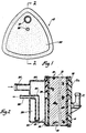
- Figure 1 is an end elevational view of a preferred embodiment of a fuel vapour storage canister employing this invention.
- Figure 2 is a sectional view of the canister, taken along line 2-2 of Figure 1.
- Referring to the drawings, a fuel vapour storage canister 10 with a horizontal axis has a
bed 12 of activated carbon adapted to adsorb fuel vapour.Bed 12 is supported betweenfoam screens 14 and 16 within ahousing 18. - At the left end of canister 10, as viewed in Figure 2,
housing 18 is closed by a partition 19 and acover 20. A fuel vapour inlet tube 24 and apurge tube 26 are formed as part ofcover 20 and open into an inlet chamber 28 betweencover 20 and partition 19. Chamber 28 opens tobed 12 through an aperture 29 in partition 19, aperture 29 being spaced substantially above the bottom of chamber 28. - The region 30 at the right end of canister 10 is open to the atmosphere through a vent tube 31 of a cover 31a. Vapour inlet tube 24 receives a mixture of fuel vapour and air discharged from a fuel tank (not shown). As the mixture flows through chamber 28, aperture 29 and
bed 12, the activated carbon inbed 12 adsorbs the fuel vapour and the air flows out through vent tube 31. - Chamber 28 serves as a trap to capture any liquid fuel that may be present in the mixture of fuel vapour and air received through inlet tube 24. By capturing the liquid fuel before it reaches
bed 12,bed 12 is protected against absorption of liquid fuel, and the activated carbon is thereby preserved for adsorption of fuel vapour. - Fuel is purged from canister 10 by applying vacuum to purge
tube 26.Purge tube 26 has a small liquid-purge hole 32 about 0.020in (0.5mm) in diameter at the lower end and a large vapour-purge hole 34 about O.IIOin (2.79mm) in diameter near the top. The vacuum applied through vapour-purge hole 34 draws air from vent tube 31 throughbed 12, and into chamber 28. The air flow throughbed 12 desorbs the fuel vapour, and the resulting mixture of air and fuel vapour is drawn out throughpurge tube 26. The vacuum applied through liquid-purge hole 32 gradually purges the liquid fuel from chamber 28, and the liquid fuel is drawn out throughpurge tube 26 along with the mixture of air and fuel vapour. - it will be noted that canister 10 has a generally triangular configuration in cross-section with the apex of the triangle at the top. This construction maximizes the capacity at the base of chamber 28 to minimize the possibility that liquid might be transferred through aperture 29 into
bed 12. - The preferred embodiment of the fuel vapour storage canister of the present invention also in- dudes therein an invention which is disclosed in, and claimed in, or co-pending European patent application No. 87 302 083.8, filed on the same date, and published as EP-A 0 242 049.
Claims (2)
Applications Claiming Priority (4)
| Application Number | Priority Date | Filing Date | Title |
|---|---|---|---|
| US85154786A | 1986-04-14 | 1986-04-14 | |
| US851547 | 1986-04-14 | ||
| US06/918,887 US4683862A (en) | 1986-04-14 | 1986-10-15 | Fuel vapor storage canister |
| US918887 | 1986-10-15 |
Publications (2)
| Publication Number | Publication Date |
|---|---|
| EP0242048A1 EP0242048A1 (en) | 1987-10-21 |
| EP0242048B1 true EP0242048B1 (en) | 1989-07-19 |
Family
ID=27127009
Family Applications (1)
| Application Number | Title | Priority Date | Filing Date |
|---|---|---|---|
| EP87302082A Expired EP0242048B1 (en) | 1986-04-14 | 1987-03-11 | Fuel vapour storage canister |
Country Status (4)
| Country | Link |
|---|---|
| US (1) | US4683862A (en) |
| EP (1) | EP0242048B1 (en) |
| CA (1) | CA1275382C (en) |
| DE (1) | DE3760342D1 (en) |
Families Citing this family (22)
| Publication number | Priority date | Publication date | Assignee | Title |
|---|---|---|---|---|
| US4836172A (en) * | 1986-10-06 | 1989-06-06 | Aisan Kogyo Kabushiki Kaisha | Canister device for use in gasoline tank |
| US4852761A (en) * | 1988-07-25 | 1989-08-01 | General Motors Corporation | In tank vapor storage canister |
| US4853009A (en) * | 1988-08-31 | 1989-08-01 | General Motors Corporation | Multi orientation fuel vapor storage canister assembly |
| DE3842994C2 (en) * | 1988-12-21 | 1994-07-07 | Audi Ag | Activated carbon filter to collect fuel vapors |
| US5002596A (en) * | 1990-05-21 | 1991-03-26 | Chrysler Corporation | Fuel vapor canister |
| JPH04247458A (en) * | 1991-02-01 | 1992-09-03 | Konica Corp | Photosensitive material for damping waterless planographic plate |
| US5119791A (en) * | 1991-06-07 | 1992-06-09 | General Motors Corporation | Vapor storage canister with liquid trap |
| US5641344A (en) * | 1994-12-05 | 1997-06-24 | Tsuchiya Mfg., Co., Ltd. | Fuel vapor treatment device |
| US5961699A (en) * | 1998-02-10 | 1999-10-05 | Hyundai Motor Company | Canister apparatus |
| US6136075A (en) * | 1999-05-03 | 2000-10-24 | Westvaco Corporation | Automotive evaporative emissions canister adsorptive restraint system |
| US6390074B1 (en) * | 2000-05-12 | 2002-05-21 | Ford Global Technologies, Inc. | Fuel assembly |
| JP2003120445A (en) * | 2001-10-05 | 2003-04-23 | Tokyo Roki Co Ltd | Air cleaner |
| JP2005538846A (en) * | 2002-09-16 | 2005-12-22 | アエロクライン・アクチボラゲット | Purifier |
| JP3892385B2 (en) * | 2002-10-22 | 2007-03-14 | 株式会社デンソー | Canister filter |
| KR100505146B1 (en) * | 2003-04-18 | 2005-08-04 | 코리아에프티 주식회사 | Canister of Automobile |
| US7132011B2 (en) * | 2003-09-02 | 2006-11-07 | Entegris, Inc. | Reactive gas filter |
| US7763104B2 (en) * | 2006-09-05 | 2010-07-27 | Visteon Global Technologies, Inc. | Hydrocarbon trap assembly |
| US20080308074A1 (en) * | 2007-06-13 | 2008-12-18 | Allen Christopher D | Evaporative emissions canister with external membrane |
| US20080308073A1 (en) * | 2007-06-13 | 2008-12-18 | Allen Christopher D | Evaporative emissions canister having an integral membrane |
| US20080308072A1 (en) * | 2007-06-13 | 2008-12-18 | Raja Banerjee | Hydrocarbon separation from air using membrane separators in recirculation tube |
| US20080308075A1 (en) * | 2007-06-13 | 2008-12-18 | Allen Christopher D | Automotive fuel system for substantially reducing hydrocarbon emissions into the atmosphere, and method |
| FR2979832B1 (en) * | 2011-09-13 | 2015-11-13 | Renault Sas | ACTIVE CHARCOAL FILTER WITH STORAGE VOLUME FOR FUEL TANK |
Family Cites Families (17)
| Publication number | Priority date | Publication date | Assignee | Title |
|---|---|---|---|---|
| US3191587A (en) * | 1965-06-29 | Device for controlling the hydrocar- bon evaporation losses from automo- tive vehicles | ||
| USRE26169E (en) | 1967-03-07 | Device for controlling the hydrocar- bon evaporation losses from automo- tive vehicles | ||
| US26169A (en) * | 1859-11-22 | Apparatus fob | ||
| US3352294A (en) * | 1965-07-28 | 1967-11-14 | Exxon Research Engineering Co | Process and device for preventing evaporation loss |
| US3393669A (en) * | 1966-05-19 | 1968-07-23 | Exxon Research Engineering Co | Apparatus and process for adsorbing and desorbing internal combustion engine fuel vapors |
| GB1217347A (en) * | 1967-06-21 | 1970-12-31 | Exxon Research Engineering Co | Fuel system for an internal combustion engine |
| DE1751160A1 (en) * | 1967-06-21 | 1971-05-13 | Esso Res And Engineering Co | Fuel system |
| DE1927046A1 (en) * | 1969-05-28 | 1970-12-10 | Porsche Kg | Device for separating fuel from the air emerging from the fuel supply system of an internal combustion engine |
| US3575152A (en) * | 1969-10-01 | 1971-04-20 | Gen Motors Corp | Vapor recovery using a plurality of progressively absorbent beds connected in series |
| US3646731A (en) * | 1970-09-02 | 1972-03-07 | Ford Motor Co | Air cleaner and fuel vapor storage assembly remotely associated with an engine |
| GB1316161A (en) * | 1970-10-16 | 1973-05-09 | Chrysler Uk | Fuel tanks |
| FR2298005A1 (en) * | 1975-01-15 | 1976-08-13 | Peugeot & Renault | PROCESS AND DEVICE FOR RECYCLING THE CARBURETOR OF HYDROCARBON VAPORS |
| CA1124594A (en) * | 1978-11-30 | 1982-06-01 | Brian W. Green | Engine with evaporation control system |
| US4203401A (en) * | 1979-01-29 | 1980-05-20 | General Motors Corporation | Evaporative emissions canister |
| US4280466A (en) * | 1979-03-26 | 1981-07-28 | General Motors Corporation | Evaporative emission control device |
| US4395991A (en) * | 1981-01-23 | 1983-08-02 | Yamaha Hatsudoki Kabushiki Kaisha | Emission preventing system of evaporated fuel for internal combustion engine |
| JPS57126127A (en) * | 1981-01-27 | 1982-08-05 | Toshiba Corp | Diffusion treating method for semiconductor wafer |
-
1986
- 1986-10-15 US US06/918,887 patent/US4683862A/en not_active Expired - Lifetime
-
1987
- 1987-03-11 EP EP87302082A patent/EP0242048B1/en not_active Expired
- 1987-03-11 DE DE8787302082T patent/DE3760342D1/en not_active Expired
- 1987-03-19 CA CA000532407A patent/CA1275382C/en not_active Expired - Lifetime
Also Published As
| Publication number | Publication date |
|---|---|
| US4683862A (en) | 1987-08-04 |
| CA1275382C (en) | 1990-10-23 |
| EP0242048A1 (en) | 1987-10-21 |
| DE3760342D1 (en) | 1989-08-24 |
Similar Documents
| Publication | Publication Date | Title |
|---|---|---|
| EP0242048B1 (en) | Fuel vapour storage canister | |
| EP0242049B1 (en) | Fuel vapour storage canister | |
| US4750465A (en) | Fuel vapor storage canister | |
| US4403587A (en) | Fuel evaporative emission control apparatus for vehicles | |
| US5878729A (en) | Air control valve assembly for fuel evaporative emission storage canister | |
| US7294179B2 (en) | Canister of vehicle | |
| US4758255A (en) | Canister for adsorbing fuel vapors | |
| US4507132A (en) | Fuel evaporation preventing device | |
| CA1151030A (en) | Proportional flow fuel vapor purge control device | |
| US4693393A (en) | Fuel vapor storage canister having tortuous vent passage | |
| JPS6055706B2 (en) | Vehicle fuel evaporation prevention device | |
| US5002596A (en) | Fuel vapor canister | |
| US6874483B2 (en) | Canister of an evaporated fuel processing system | |
| JP2001182631A (en) | Internal combustion engine canister | |
| US4703736A (en) | Fuel vapor containment device | |
| US7353809B2 (en) | Evaporative emissions canister with integral liquid fuel trap | |
| EP0556488A1 (en) | Fuel vapour storage canister | |
| KR20190004800A (en) | Fuel vapor filters for tank ventilation of automobiles with improved charging characteristics | |
| KR100265313B1 (en) | Air bleeder for a fuel tank of an internal cumbustion engine | |
| JP3610757B2 (en) | Canister | |
| HU218772B (en) | Activated carbon filter for motor vehicles | |
| JPH05280435A (en) | Evaporated fuel treating device | |
| JPH0533734A (en) | Canister | |
| JPS6119827B2 (en) | ||
| RU2176745C2 (en) | Fuel fumes entrapping system adsorber |
Legal Events
| Date | Code | Title | Description |
|---|---|---|---|
| PUAI | Public reference made under article 153(3) epc to a published international application that has entered the european phase |
Free format text: ORIGINAL CODE: 0009012 |
|
| 17P | Request for examination filed |
Effective date: 19870318 |
|
| AK | Designated contracting states |
Kind code of ref document: A1 Designated state(s): DE FR GB IT |
|
| 17Q | First examination report despatched |
Effective date: 19880503 |
|
| GRAA | (expected) grant |
Free format text: ORIGINAL CODE: 0009210 |
|
| ITF | It: translation for a ep patent filed | ||
| AK | Designated contracting states |
Kind code of ref document: B1 Designated state(s): DE FR GB IT |
|
| REF | Corresponds to: |
Ref document number: 3760342 Country of ref document: DE Date of ref document: 19890824 |
|
| ET | Fr: translation filed | ||
| PLBE | No opposition filed within time limit |
Free format text: ORIGINAL CODE: 0009261 |
|
| STAA | Information on the status of an ep patent application or granted ep patent |
Free format text: STATUS: NO OPPOSITION FILED WITHIN TIME LIMIT |
|
| 26N | No opposition filed | ||
| ITTA | It: last paid annual fee | ||
| REG | Reference to a national code |
Ref country code: GB Ref legal event code: IF02 |
|
| PGFP | Annual fee paid to national office [announced via postgrant information from national office to epo] |
Ref country code: GB Payment date: 20030310 Year of fee payment: 17 |
|
| PGFP | Annual fee paid to national office [announced via postgrant information from national office to epo] |
Ref country code: FR Payment date: 20030313 Year of fee payment: 17 |
|
| PG25 | Lapsed in a contracting state [announced via postgrant information from national office to epo] |
Ref country code: GB Free format text: LAPSE BECAUSE OF NON-PAYMENT OF DUE FEES Effective date: 20040311 |
|
| GBPC | Gb: european patent ceased through non-payment of renewal fee |
Effective date: 20040311 |
|
| PG25 | Lapsed in a contracting state [announced via postgrant information from national office to epo] |
Ref country code: FR Free format text: LAPSE BECAUSE OF NON-PAYMENT OF DUE FEES Effective date: 20041130 |
|
| REG | Reference to a national code |
Ref country code: FR Ref legal event code: ST |
|
| PG25 | Lapsed in a contracting state [announced via postgrant information from national office to epo] |
Ref country code: IT Free format text: LAPSE BECAUSE OF NON-PAYMENT OF DUE FEES;WARNING: LAPSES OF ITALIAN PATENTS WITH EFFECTIVE DATE BEFORE 2007 MAY HAVE OCCURRED AT ANY TIME BEFORE 2007. THE CORRECT EFFECTIVE DATE MAY BE DIFFERENT FROM THE ONE RECORDED. Effective date: 20050311 |
|
| PGFP | Annual fee paid to national office [announced via postgrant information from national office to epo] |
Ref country code: DE Payment date: 20050530 Year of fee payment: 19 |
|
| PG25 | Lapsed in a contracting state [announced via postgrant information from national office to epo] |
Ref country code: DE Free format text: LAPSE BECAUSE OF NON-PAYMENT OF DUE FEES Effective date: 20061003 |