EP0242008B1 - Blowout preventer - Google Patents
Blowout preventer Download PDFInfo
- Publication number
- EP0242008B1 EP0242008B1 EP87300131A EP87300131A EP0242008B1 EP 0242008 B1 EP0242008 B1 EP 0242008B1 EP 87300131 A EP87300131 A EP 87300131A EP 87300131 A EP87300131 A EP 87300131A EP 0242008 B1 EP0242008 B1 EP 0242008B1
- Authority
- EP
- European Patent Office
- Prior art keywords
- packer
- blowout preventer
- ram
- inserts
- recesses
- Prior art date
- Legal status (The legal status is an assumption and is not a legal conclusion. Google has not performed a legal analysis and makes no representation as to the accuracy of the status listed.)
- Expired
Links
Images


Classifications
-
- E—FIXED CONSTRUCTIONS
- E21—EARTH DRILLING; MINING
- E21B—EARTH DRILLING, e.g. DEEP DRILLING; OBTAINING OIL, GAS, WATER, SOLUBLE OR MELTABLE MATERIALS OR A SLURRY OF MINERALS FROM WELLS
- E21B33/00—Sealing or packing boreholes or wells
- E21B33/02—Surface sealing or packing
- E21B33/03—Well heads; Setting-up thereof
- E21B33/06—Blow-out preventers, i.e. apparatus closing around a drill pipe, e.g. annular blow-out preventers
- E21B33/061—Ram-type blow-out preventers, e.g. with pivoting rams
- E21B33/062—Ram-type blow-out preventers, e.g. with pivoting rams with sliding rams
Abstract
Description
- This invention relates to blowout preventers.
- Blowout preventers are used on wells to control the pressure which may build within the well. They have been used on wells to close on dual tubing strings. It is desirable that when running or pulling such strings that they be supported by the blowout preventer rams. Normal support of a tubing string by a blowout preventer is accomplished by resting the joint enlargement on the rams. With dual strings in more recent wells which are much deeper, such support of both strings on the rams is not possible because the joints are normally vertically staggered and the length of the strings are such that both would not be supported adequately with only one resting on the rams. Additionally, tubing strings have safety valves installed therein and require the running of their control lines, often in encapsulated form along the exterior of the strings. Supporting the dual strings with their encapsulated control lines on a blowout preventer has not been possible with existing structures.
- One prior blowout preventer structure was suitable for handling dual strings. It included an upper set of rams which sealed on the dual strings after they had been properly oriented by the lower set of rams. This structure is shown in U.S. Patent No. 4,215,747. Another prior structure includes shear rams in an upper preventer and slip bowl rams in the lower preventer as shown in U.S. Patent No. 4,043,389.
- A blowout preventer structure shown in U.S. Patent No. 4,057,887 includes upper and lower rams for a single string which has its shoulder supported on the lower ram, the upper and lower rams provide sealing on the string and intermediate rams are used for unthreading the string at the joint resting on the lower ram.
- U.S. Patent Nos. 2,746,710, 2,855,172, 2,947,508 and 4,229,012 all disclose blowout preventer structures in which the packing includes a series of inserts which support the packing material and which can move inwardly in varying degrees to accommodate the shape of the string on which the rams close. None of these structures are suitable for supporting dual strings and their encapsulated control lines and sealing about the dual strings and the control line.
- According to one aspect of the present invention there is provided a blowout preventer comprising a body having a bore therethrough and opposed aligned guideways extending outward from said bore, a ram in each of said guideways, means for reciprocating said rams in said guideways to retract from said bore and to move into said bore, each of said rams having a ram body having a packer receiving slot across its front surface facing said bore and dual arcuate recesses extending through the front face of said ram body in a direction parallel to the axis of said bore, seal means for sealing between the top and sides of said ram body and the walls of the guideway in which it is positioned, and a packer of resilient material positioned in said receiving slot having its sides in engagement with said seal means to complete the side sealing against the walls of its guideway, said packer having dual arcuate front recesses aligned with the recesses of said ram body, characterised by a plurality of tube supporting means lining a substantial portion of the recesses of said packer and a plurality of independently movable inserts embedded in said packer to support the resilient material in sealing position against a tubing string and its encapsulated control lines.
- According to another aspect of the present invention there is provided a blowout preventer packer for use with a blowout preventer comprising a packer body of resilient material having dual arcuate recesses on its front face, and characterised by tubing support means embedded in said packer body, and a plurality of independently movable reinforcing inserts embedded in said packer body.
- Prior to closing the rams of the improved blowout preventer of the present invention, the dual tubing strings should be properly oriented so they will be correctly engaged by the rams. One method of accomplishing this is to use the aligning apparatus disclosed in U.S. Patent No. 4,215,747 installed above the blowout preventer of the present invention.
- The invention will be described now by way of example only with particular reference to the accompanying drawings. In the drawings:
- FIGURE 1 is an elevation view with portions in section to show the open rams within the body.
- FIGURE 2 is a sectional view taken along 2-2 in FIGURE 1.
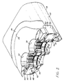
- FIGURE 3 is a perspective view of one of the improved rams of the present invention.
- FIGURE 4 is a sectional plan view of the blowout preventer shown schematically to illustrate the closing on tubing strings.
- FIGURE 5 is a partial view similar to FIGURE 4 showing the position of the ram closed but with the encapsulated control line in a different position.
- FIGURE 6 is a front view of the improved packer of the present invention.
- FIGURE 7 is a sectional view of the packer taken along line 7-7 in FIGURE 6.
- Improved
blowout preventer 10, as shown, includesbody 12 havingvertical bore 14 extending therethrough and opposedaligned guideways 16 extending outward frombore 14. Rams 18 are movably positioned withinguideways 16 and are moved therein by suitable pressureresponsive means 20, such as pistons. As shown in FIGURES 2 and 3rams 18 each includebody 22 which includes suitable means 24 for connecting to pressureresponsive means 20,top seal 26 positioned ingroove 28 extending across the top ofbody 22 and into sealing engagement with the sides ofpacker 30 at the sides ofbody 22. The inner or front face ofbody 22 includes two semicircular vertically extendingrecesses 32 andtransverse slot 34 opening to bore 14.Mud slot 36 extends along the lower portion ofbody 22 to provide communication frombore 14 belowrams 18 to the rear or outer face ofbody 22. - As can be seen in FIGURE 3,
packer 30 is positioned intransverse slot 34 ofram body 22 and eachpacker 30 has two semicircular vertically extendingrecesses 38 for closing on dual production strings 40 (FIGURES 4 and 5) extending throughbore 14. Eachpacker 30 includesresilient packing 42 havingupper gripping section 44 andlower sealing section 46.Lower sealing section 46 includes a plurality ofupper metal inserts 48 andlower metal inserts 50 embedded inresilient packing 42. As best seen in FIGURES 4 through 7, eachinsert packing 42 at each side of therecesses 38. Inserts 52 include upper and lower flanges 53 withintegral neck 54 extending between flanges 53.Inserts resilient packing 42.Upper gripping section 44 includes a plurality ofslip segments 56 embedded in packing 42 in surrounding relationship torecesses 38. Each ofslip segments 56 has a plurality of upwardly facing teeth 57 (FIGURE 7) facing inwardly toward the center of theirrecesses 38.Support segments 58 are positioned at the inner edges ofgripping section 44 in supporting relationship toslips 56 to assist in maintainingslips 56 in their desired relationship in position to come into gripping engagement with the production string in its recess.Upper plates 60 are positioned on the upper surface of packing 42 at each side ofgripping section 44.Lower plates 62 are positioned on the lower surface ofpacking 42 at each side ofsealing section 46 as clearly shown in FIGURES 3 and 6. - The specific structure of each
slip 56 andinserts resilient packing 42 with the material of packing 42 betweeninserts recess 64 in the rear surface ofslips 56.Pins 65 secured to packer 30 are used to securepacker 30 to itsram 18 in a manner known in the art and disclosed in U.S. Patent No. 3,817,326 and others. - In FIGURE 4, a view of
rams 18 ofblowout preventer 10 is illustrated closed ondual production strings 40. Each ofstrings 40 includes its own attached encapsulatedcontrol line 66. In one ofrecesses 32,control line 66 is positioned on the side ofstring 40 facing the center of the ram which isengaging string 40. In this position, encapsulatedcontrol line 66 is compressed radially and extends circumferentially so that it is engaged by the center two slips and the other two slips move into direct gripping engagement withstring 40. The two slips on one side and four slips in theother recess 32 engaging theother string 40 is sufficient engagement to fully support the weight of both strings. Theother string 40 is shown with itscontrol line 66 positioned at the side so that when engaged, as shown, it is compressed from the side so that it is slightly smaller in the circumferential direction with respect tostring 40 and is slightly larger in the radial direction. Bothstrings 40 are supported and packer 30 seals against them. - FIGURE 7 illustrates another possible position of
control line 66 with respect toupper gripping section 44. In thisposition control line 66 is engaged by the two slips on the side of the recess and is partially compressed radially and the portion of the encapsulation at the side of theside slip 56a is slightly expanded radially and circumferentially. In all positions whichcontrol lines 66 may assume thepipe strings 40 are properly supported andrams 18 are set against and seal aroundstrings 40 and encapsulatedcontrol lines 66.
Claims (12)
- A blowout preventer comprising a body (12) having a bore (14) therethrough and opposed aligned guideways (16) extending outward from said bore, a ram (18) in each of said guideways, means (20) for reciprocating said rams in said guideways to retract from said bore and to move into said bore, each of said rams having a ram body (22) having a packer receiving slot (34) across its front surface facing said bore and dual arcuate recesses (32) extending through the front face of said ram body in a direction parallel to the axis of said bore (14), seal means (26) for sealing between the top and sides of said ram body and the walls of the guideway in which it is positioned, and a packer (30) of resilient material positioned in said receiving slot (34) having its sides in engagement with said seal means to complete the side sealing against the walls of its guideway, said packer having dual arcuate front recesses (38) aligned with the recesses (32) of said ram body, characterised by a plurality of tube supporting means (44) lining a substantial portion of the recesses of said packer and a plurality of independently movable inserts (48, 50) embedded in said packer (30) to support the resilient material in sealing position against a tubing string and its encapsulated control lines.
- A blowout preventer according to claim 1, wherein said tube supporting means (44) includes a plurality of gripping slips (56) embedded in said packer (20) and being movable radially of their recess to move into tight gripping engagement with a tubing string extending through said recess.
- A blowout preventer according to claim 1 or claim 2, wherein said inserts (48, 50) include a plurality of strip shaped inserts (48) embedded in said packer immediately below said gripping slips parallel to the axis of their ram.
- A blowout preventer according to claim 3, wherein said inserts include a plurality of strip shaped inserts (50) embedded in said packer on the lower surface of said packer parallel to the axis of their ram.
- A blowout preventer according to claim 4, including an end insert (52) embedded in said packer at each side of said arcuate recesses, said end inserts having upper and lower flanges (53), and an integral neck (54) extending between said flanges.
- A blowout preventer packer for use with a blowout preventer according to any preceding claim comprising a packer body (30) of resilient material having dual arcuate recesses (38) on its front face, and characterised by tubing support means embedded in said packer body, and a plurality of independently movable reinforcing inserts (48, 50) embedded in said packer body.
- A blowout preventer packer according to claim 6, wherein said tubing supporting means includes a plurality of gripping slips (56).
- A blowout preventer packer according to claim 7, wherein said gripping slips (56) are independently movable.
- A blowout preventer according to claim 8, wherein said gripping slips (56) are arranged to move into gripping engagement with a tubing string recess to support said string against movement in said recess.
- A blowout preventer packer according to claim 6, wherein said inserts (48, 50) include a plurality of strips (48) positioned immediately under said tubing supporting means and extending perpendicular to the front face of said packer.
- A blowout preventer packer according to claim 10, including a plurality of strips (50) positioned at the lower side of said packer body and parallel to said upper strips.
- A blowout preventer packer according to any one of claims 6 to 11, wherein said body includes dual arcuate recesses (38) on its front face, and said gripping slips (56) surround each recess.
Priority Applications (1)
| Application Number | Priority Date | Filing Date | Title |
|---|---|---|---|
| AT87300131T ATE70889T1 (en) | 1986-04-18 | 1987-01-08 | BREAK OUT VALVE. |
Applications Claiming Priority (2)
| Application Number | Priority Date | Filing Date | Title |
|---|---|---|---|
| US85360186A | 1986-04-18 | 1986-04-18 | |
| US853601 | 1986-04-18 |
Publications (3)
| Publication Number | Publication Date |
|---|---|
| EP0242008A2 EP0242008A2 (en) | 1987-10-21 |
| EP0242008A3 EP0242008A3 (en) | 1988-10-26 |
| EP0242008B1 true EP0242008B1 (en) | 1991-12-27 |
Family
ID=25316477
Family Applications (1)
| Application Number | Title | Priority Date | Filing Date |
|---|---|---|---|
| EP87300131A Expired EP0242008B1 (en) | 1986-04-18 | 1987-01-08 | Blowout preventer |
Country Status (8)
| Country | Link |
|---|---|
| US (1) | US5013005A (en) |
| EP (1) | EP0242008B1 (en) |
| JP (1) | JPH073152B2 (en) |
| AT (1) | ATE70889T1 (en) |
| CA (1) | CA1305048C (en) |
| DE (1) | DE3775446D1 (en) |
| NO (1) | NO173751C (en) |
| SG (1) | SG53992G (en) |
Families Citing this family (38)
| Publication number | Priority date | Publication date | Assignee | Title |
|---|---|---|---|---|
| US5575451A (en) * | 1995-05-02 | 1996-11-19 | Hydril Company | Blowout preventer ram for coil tubing |
| US6352120B1 (en) | 1999-02-08 | 2002-03-05 | Hydril Company | Packer insert for sealing on multiple items in the wellbore |
| AU774169B2 (en) | 1999-09-22 | 2004-06-17 | Baker Hughes Incorporated | Safety slip ram |
| CA2311036A1 (en) | 2000-06-09 | 2001-12-09 | Oil Lift Technology Inc. | Pump drive head with leak-free stuffing box, centrifugal brake and polish rod locking clamp |
| US6296225B1 (en) | 2000-06-29 | 2001-10-02 | Cooper Cameron Corporation | Ram bore profile for variable bore packer ram in a ram type blowout preventer |
| US7331562B2 (en) * | 2005-11-07 | 2008-02-19 | Varco I/P, Inc. | Blowout preventer with breech assembly |
| US8424607B2 (en) * | 2006-04-25 | 2013-04-23 | National Oilwell Varco, L.P. | System and method for severing a tubular |
| US8720564B2 (en) | 2006-04-25 | 2014-05-13 | National Oilwell Varco, L.P. | Tubular severing system and method of using same |
| US7367396B2 (en) | 2006-04-25 | 2008-05-06 | Varco I/P, Inc. | Blowout preventers and methods of use |
| US8720565B2 (en) * | 2006-04-25 | 2014-05-13 | National Oilwell Varco, L.P. | Tubular severing system and method of using same |
| US8844898B2 (en) | 2009-03-31 | 2014-09-30 | National Oilwell Varco, L.P. | Blowout preventer with ram socketing |
| EP2576962B1 (en) | 2010-05-28 | 2015-05-06 | National Oilwell Varco, L.P. | System and method for severing a tubular |
| US8430167B2 (en) * | 2010-06-29 | 2013-04-30 | Chevron U.S.A. Inc. | Arcuate control line encapsulation |
| US8544538B2 (en) | 2010-07-19 | 2013-10-01 | National Oilwell Varco, L.P. | System and method for sealing a wellbore |
| US8540017B2 (en) | 2010-07-19 | 2013-09-24 | National Oilwell Varco, L.P. | Method and system for sealing a wellbore |
| US8162046B2 (en) | 2010-08-17 | 2012-04-24 | T-3 Property Holdings, Inc. | Blowout preventer with shearing blades |
| US8807219B2 (en) | 2010-09-29 | 2014-08-19 | National Oilwell Varco, L.P. | Blowout preventer blade assembly and method of using same |
| US8505870B2 (en) * | 2011-02-02 | 2013-08-13 | Hydril Usa Manufacturing Llc | Shear blade geometry and method |
| KR20150092371A (en) | 2011-03-09 | 2015-08-12 | 내셔널 오일웰 바르코 엘.피. | Method and apparatus for sealing a wellbore |
| US10000987B2 (en) | 2013-02-21 | 2018-06-19 | National Oilwell Varco, L.P. | Blowout preventer monitoring system and method of using same |
| CN103216206A (en) * | 2013-03-03 | 2013-07-24 | 魏辛武 | Deviation-prevention biconical sealing rubber block |
| US9879498B2 (en) * | 2015-04-21 | 2018-01-30 | Axon Pressure Products, Inc. | Shear block design for blowout preventer |
| US9976374B2 (en) * | 2015-11-20 | 2018-05-22 | Cameron International Corporation | Side packer assembly with support member for ram blowout preventer |
| US10161212B2 (en) * | 2015-11-24 | 2018-12-25 | Cameron International Corporation | Packer assembly with multiple different inserts for blowout preventer |
| US10087698B2 (en) * | 2015-12-03 | 2018-10-02 | General Electric Company | Variable ram packer for blowout preventer |
| US10202817B2 (en) * | 2016-08-11 | 2019-02-12 | Cameron International Corporation | Packer assembly with inserts for blowout preventer |
| US10961801B2 (en) | 2016-12-14 | 2021-03-30 | Cameron International Corporation | Fracturing systems and methods with rams |
| US11834941B2 (en) | 2016-12-14 | 2023-12-05 | Cameron International Corporation | Frac stack well intervention |
| US10961800B2 (en) | 2016-12-14 | 2021-03-30 | Cameron International Corporation | FRAC stacks with rams to close bores and control flow of fracturing fluid |
| US10961802B2 (en) | 2016-12-14 | 2021-03-30 | Cameron International Corporation | Frac stack well intervention |
| US11053764B2 (en) * | 2019-01-09 | 2021-07-06 | Schlumberger Technology Corporation | Hang off ram preventer |
| US11136849B2 (en) * | 2019-11-05 | 2021-10-05 | Saudi Arabian Oil Company | Dual string fluid management devices for oil and gas applications |
| RU2730162C1 (en) * | 2020-04-17 | 2020-08-19 | Публичное акционерное общество «Татнефть» имени В.Д. Шашина | Preventer for wells with two-row string |
| US11421508B2 (en) | 2020-04-24 | 2022-08-23 | Cameron International Corporation | Fracturing valve systems and methods |
| RU2736022C1 (en) * | 2020-07-24 | 2020-11-11 | Публичное акционерное общество «Татнефть» имени В.Д. Шашина | Preventer for a well with two-row string and inclined mouth |
| US11905791B2 (en) | 2021-08-18 | 2024-02-20 | Saudi Arabian Oil Company | Float valve for drilling and workover operations |
| US11913298B2 (en) | 2021-10-25 | 2024-02-27 | Saudi Arabian Oil Company | Downhole milling system |
| CN114876400B (en) * | 2022-06-20 | 2023-05-26 | 易初机械装备有限公司 | Coiled tubing blowout prevention system |
Family Cites Families (11)
| Publication number | Priority date | Publication date | Assignee | Title |
|---|---|---|---|---|
| US2746710A (en) * | 1952-10-29 | 1956-05-22 | Petroleum Mechanical Dev Corp | Blowout preventer and ram therefor |
| US2855172A (en) * | 1956-04-06 | 1958-10-07 | Cameron Iron Works Inc | Blowout preventer and ram therefor |
| US2947508A (en) * | 1956-04-06 | 1960-08-02 | Cameron Iron Works Inc | Blowout preventer and ram therefor |
| US3554278A (en) * | 1969-07-31 | 1971-01-12 | Exxon Production Research Co | Pipe alignment apparatus |
| US3817326A (en) * | 1972-06-16 | 1974-06-18 | Cameron Iron Works Inc | Ram-type blowout preventer |
| US4057887A (en) * | 1974-05-06 | 1977-11-15 | Cameron Iron Works, Inc. | Pipe disconnecting apparatus |
| US3955622A (en) * | 1975-06-09 | 1976-05-11 | Regan Offshore International, Inc. | Dual drill string orienting apparatus and method |
| US4043389A (en) * | 1976-03-29 | 1977-08-23 | Continental Oil Company | Ram-shear and slip device for well pipe |
| US4229012A (en) * | 1978-04-28 | 1980-10-21 | Cameron Iron Works, Inc. | Variable bore packer assembly for ram-type blowout preventers |
| US4215747A (en) * | 1978-06-05 | 1980-08-05 | Cameron Iron Works, Inc. | Blowout preventer with tubing aligning apparatus |
| US4506858A (en) * | 1983-05-31 | 1985-03-26 | Otis Engineering Corporation | Wireline valve inner seal |
-
1987
- 1987-01-08 DE DE8787300131T patent/DE3775446D1/en not_active Expired - Fee Related
- 1987-01-08 EP EP87300131A patent/EP0242008B1/en not_active Expired
- 1987-01-08 AT AT87300131T patent/ATE70889T1/en not_active IP Right Cessation
- 1987-01-09 CA CA000527019A patent/CA1305048C/en not_active Expired - Fee Related
- 1987-01-20 JP JP62011216A patent/JPH073152B2/en not_active Expired - Fee Related
- 1987-04-14 NO NO871587A patent/NO173751C/en unknown
- 1987-12-17 US US07/134,084 patent/US5013005A/en not_active Expired - Lifetime
-
1992
- 1992-05-15 SG SG539/92A patent/SG53992G/en unknown
Also Published As
| Publication number | Publication date |
|---|---|
| DE3775446D1 (en) | 1992-02-06 |
| EP0242008A2 (en) | 1987-10-21 |
| JPH073152B2 (en) | 1995-01-18 |
| NO871587D0 (en) | 1987-04-14 |
| US5013005A (en) | 1991-05-07 |
| SG53992G (en) | 1992-07-24 |
| NO173751C (en) | 1994-01-26 |
| EP0242008A3 (en) | 1988-10-26 |
| NO871587L (en) | 1987-10-19 |
| ATE70889T1 (en) | 1992-01-15 |
| JPS62258090A (en) | 1987-11-10 |
| CA1305048C (en) | 1992-07-14 |
| NO173751B (en) | 1993-10-18 |
Similar Documents
| Publication | Publication Date | Title |
|---|---|---|
| EP0242008B1 (en) | Blowout preventer | |
| US5515926A (en) | Apparatus and method for installing coiled tubing in a well | |
| US4341264A (en) | Wellhead shearing apparatus | |
| US4842061A (en) | Casing hanger packoff with C-shaped metal seal | |
| US4708202A (en) | Drillable well-fluid flow control tool | |
| CA2224668C (en) | Method and apparatus for hybrid element casing packer for cased-hole applications | |
| EP0439896B1 (en) | Variable bore packer for a ram type blowout preventer | |
| CA1081118A (en) | Blowout preventer packing unit with slanted reinforcing inserts | |
| MXPA06012743A (en) | Improved packer. | |
| CA2472792C (en) | Variable bore ram | |
| CA1178196A (en) | Well blowout preventer, and packing element | |
| EP0898048B1 (en) | Slip for use in a subterranean well | |
| US20140183382A1 (en) | Dual compound variable ram packer | |
| US3530934A (en) | Segmented frangible slips with guide pins | |
| EP0103786A2 (en) | Ram-type blowout preventer | |
| EP0510778B1 (en) | Wellhead structure | |
| US5732772A (en) | Dual split tubing hanger | |
| US4476935A (en) | Safety valve apparatus and method | |
| EP0221154B1 (en) | Mechanical drive packer | |
| CA2011923A1 (en) | Hydraulically actuated liner hanger | |
| US3295600A (en) | Underwater production method | |
| US4447037A (en) | Well blowout preventer, and packing element | |
| US4508312A (en) | Ram-type blowout preventer | |
| EP0647763B1 (en) | Blowout preventer with removable packer | |
| EP3959415A1 (en) | Blowout preventer shearing ram |
Legal Events
| Date | Code | Title | Description |
|---|---|---|---|
| PUAI | Public reference made under article 153(3) epc to a published international application that has entered the european phase |
Free format text: ORIGINAL CODE: 0009012 |
|
| AK | Designated contracting states |
Kind code of ref document: A2 Designated state(s): AT BE CH DE FR GB IT LI LU NL SE |
|
| PUAL | Search report despatched |
Free format text: ORIGINAL CODE: 0009013 |
|
| AK | Designated contracting states |
Kind code of ref document: A3 Designated state(s): AT BE CH DE FR GB IT LI LU NL SE |
|
| 17P | Request for examination filed |
Effective date: 19890401 |
|
| 17Q | First examination report despatched |
Effective date: 19890823 |
|
| RAP1 | Party data changed (applicant data changed or rights of an application transferred) |
Owner name: COOPER INDUSTRIES,INC. |
|
| RAP1 | Party data changed (applicant data changed or rights of an application transferred) |
Owner name: COOPER INDUSTRIES INC. |
|
| GRAA | (expected) grant |
Free format text: ORIGINAL CODE: 0009210 |
|
| AK | Designated contracting states |
Kind code of ref document: B1 Designated state(s): AT BE CH DE FR GB IT LI LU NL SE |
|
| PG25 | Lapsed in a contracting state [announced via postgrant information from national office to epo] |
Ref country code: IT Free format text: LAPSE BECAUSE OF FAILURE TO SUBMIT A TRANSLATION OF THE DESCRIPTION OR TO PAY THE FEE WITHIN THE PRESCRIBED TIME-LIMIT;WARNING: LAPSES OF ITALIAN PATENTS WITH EFFECTIVE DATE BEFORE 2007 MAY HAVE OCCURRED AT ANY TIME BEFORE 2007. THE CORRECT EFFECTIVE DATE MAY BE DIFFERENT FROM THE ONE RECORDED. Effective date: 19911227 Ref country code: BE Effective date: 19911227 Ref country code: CH Effective date: 19911227 Ref country code: AT Effective date: 19911227 Ref country code: SE Effective date: 19911227 Ref country code: LI Effective date: 19911227 |
|
| REF | Corresponds to: |
Ref document number: 70889 Country of ref document: AT Date of ref document: 19920115 Kind code of ref document: T |
|
| PGFP | Annual fee paid to national office [announced via postgrant information from national office to epo] |
Ref country code: AT Payment date: 19920121 Year of fee payment: 6 |
|
| REF | Corresponds to: |
Ref document number: 3775446 Country of ref document: DE Date of ref document: 19920206 |
|
| PGFP | Annual fee paid to national office [announced via postgrant information from national office to epo] |
Ref country code: SE Payment date: 19920221 Year of fee payment: 6 |
|
| ET | Fr: translation filed | ||
| PGFP | Annual fee paid to national office [announced via postgrant information from national office to epo] |
Ref country code: LU Payment date: 19920325 Year of fee payment: 6 |
|
| REG | Reference to a national code |
Ref country code: CH Ref legal event code: PL |
|
| EPTA | Lu: last paid annual fee | ||
| PLBE | No opposition filed within time limit |
Free format text: ORIGINAL CODE: 0009261 |
|
| STAA | Information on the status of an ep patent application or granted ep patent |
Free format text: STATUS: NO OPPOSITION FILED WITHIN TIME LIMIT |
|
| 26N | No opposition filed | ||
| PG25 | Lapsed in a contracting state [announced via postgrant information from national office to epo] |
Ref country code: LU Free format text: LAPSE BECAUSE OF NON-PAYMENT OF DUE FEES Effective date: 19930108 |
|
| PGFP | Annual fee paid to national office [announced via postgrant information from national office to epo] |
Ref country code: NL Payment date: 19930131 Year of fee payment: 7 |
|
| PG25 | Lapsed in a contracting state [announced via postgrant information from national office to epo] |
Ref country code: NL Effective date: 19940801 |
|
| NLV4 | Nl: lapsed or anulled due to non-payment of the annual fee | ||
| REG | Reference to a national code |
Ref country code: GB Ref legal event code: 732E |
|
| REG | Reference to a national code |
Ref country code: GB Ref legal event code: IF02 |
|
| PGFP | Annual fee paid to national office [announced via postgrant information from national office to epo] |
Ref country code: FR Payment date: 20030107 Year of fee payment: 17 |
|
| PGFP | Annual fee paid to national office [announced via postgrant information from national office to epo] |
Ref country code: DE Payment date: 20030131 Year of fee payment: 17 |
|
| PG25 | Lapsed in a contracting state [announced via postgrant information from national office to epo] |
Ref country code: DE Free format text: LAPSE BECAUSE OF NON-PAYMENT OF DUE FEES Effective date: 20040803 |
|
| PG25 | Lapsed in a contracting state [announced via postgrant information from national office to epo] |
Ref country code: FR Free format text: LAPSE BECAUSE OF NON-PAYMENT OF DUE FEES Effective date: 20040930 |
|
| REG | Reference to a national code |
Ref country code: FR Ref legal event code: ST |
|
| PGFP | Annual fee paid to national office [announced via postgrant information from national office to epo] |
Ref country code: GB Payment date: 20051209 Year of fee payment: 20 |
|
| PG25 | Lapsed in a contracting state [announced via postgrant information from national office to epo] |
Ref country code: GB Free format text: LAPSE BECAUSE OF EXPIRATION OF PROTECTION Effective date: 20070107 |
|
| REG | Reference to a national code |
Ref country code: GB Ref legal event code: PE20 |