EP0103786A2 - Ram-type blowout preventer - Google Patents
Ram-type blowout preventer Download PDFInfo
- Publication number
- EP0103786A2 EP0103786A2 EP83108521A EP83108521A EP0103786A2 EP 0103786 A2 EP0103786 A2 EP 0103786A2 EP 83108521 A EP83108521 A EP 83108521A EP 83108521 A EP83108521 A EP 83108521A EP 0103786 A2 EP0103786 A2 EP 0103786A2
- Authority
- EP
- European Patent Office
- Prior art keywords
- ram
- recess
- blowout preventer
- type blowout
- backing portion
- Prior art date
- Legal status (The legal status is an assumption and is not a legal conclusion. Google has not performed a legal analysis and makes no representation as to the accuracy of the status listed.)
- Granted
Links
Images
Classifications
-
- E—FIXED CONSTRUCTIONS
- E21—EARTH DRILLING; MINING
- E21B—EARTH DRILLING, e.g. DEEP DRILLING; OBTAINING OIL, GAS, WATER, SOLUBLE OR MELTABLE MATERIALS OR A SLURRY OF MINERALS FROM WELLS
- E21B33/00—Sealing or packing boreholes or wells
- E21B33/02—Surface sealing or packing
- E21B33/03—Well heads; Setting-up thereof
- E21B33/06—Blow-out preventers, i.e. apparatus closing around a drill pipe, e.g. annular blow-out preventers
- E21B33/061—Ram-type blow-out preventers, e.g. with pivoting rams
- E21B33/062—Ram-type blow-out preventers, e.g. with pivoting rams with sliding rams
Definitions
- Blowout preventers have.long been used in maintaining control of oil and gas wells during drilling. Usually several units are used in one stack. This allows blind rams and different size pipe rams to be available in a single stack. After many uses under pressure blind rams and pipe rams may require that the front packings be changed.
- Prior blowout preventers have utilized front packings which are removable from the ram. This allows the ram to be used in a variety of applications. In most cases the major portion of the front packing is undamaged but the entire packing is replaced whenever its central pipe sealing portion is damaged.
- the present invention relates to an improved ram-type blowout preventer in which the ram front packing includes a backing portion and a replaceable face sealing or insert portion which are inter-engageable with each other so that when installed in the ram packer slot they are held together.
- An object of the present invention is to provide an improved ram-type blowout preventer which can be used as a blind ram blowout preventer or as a pipe ram blowout preventer for different pipe sizes without the expense of carrying a complete stock of ram front packers.
- Another object is to provide an improved ram front packer for a ram-type blowout preventer which after wear or damage can be inexpensively replaced.
- a further object is to provide .an improved ram front packer for a ram-type blowout preventer allowing an improved seal without sacrificing the strength and integrity of the front packer.
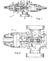
- Blowout preventer 10 is shown having body 12 through which central bore 14 extends with opposed aligned guideways 16 extending outward from bore 14 as shown in FIGURES 1 and 2.
- Ram 18 is moved in guideway 16 by suitable actuator 20 connected to ram 18 by connecting rod 22.
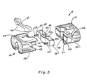
- Ram 18 includes body 24, ram front packing 26 positioned in front recess 28 and packing seal 30 which is positioned in a groove 32 in body 24 that extends along the sides and across the top of body 24 and seal 30 seals against ram front packing 26 as shown in FIGURE 5 and seals against the interior of the guideway 16.
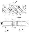
- R am front packing 26 is best seen in FIGURES 3 and 4 and includes backing portion 36 and replaceable insert portion 38.
- Backing portion 36 includes elastomeric material or body 40 with upper and lower reinforcing plates 42 and 44 bonded thereto or integrally formed therein.
- Backing portion 36 includes recess 46 in its forward face 48.
- Recess 46 includes re-entrant portions 50.
- Insert portion 38 includes elastomeric material or body 52 with upper and lower retaining plates 54 and 56 bonded thereto or integrally formed therein.
- insert portion 38 has a shape which fits closely into recess 46 with lips 58 fitting closely into re-entrant portions 50 of recess 46.
- Retaining plates 54 and 56 are substantially flush with reinforcing plates 42 and 44.
- Lugs 60 extend from the rear of packing 26 and are used to secure packing 26 into recess 28 in ram 18.
- Insert portion 38 includes pipe receiving recess 62 of a preselected size in its front face 64. If desired recess 62 may be omitted if packer 26 is to be in the form of a blind ram as indicated by the dashed lines in FIGURE 4.
- packer 26 functions as other ram packers with several advantages not present in other packers.
- front packer 26 can be used as a packer for a blind ram or a pipe ram in a variety of sizes.
- the replacement of insert 38 provides a substantially new ram front packer insert for a fraction of the cost of an entire ram front packer.
- different hardness of elastomeric materials can be used in backing portion 36 and in insert portion 38 to allow better sealing against pipe without sacrificing the strength and integrity of the packer.
- body 52 of insert 38 may be made of a low coefficient of friction material such as Teflon as manufactured by DuPont Company.
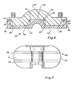
- Packer 66 includes backing portion 68 and replaceable insert portion 70.
- Insert 70 traverses essentially the entire front of packer 66 and includes elastomeric material or body 72 with upper and lower retaining plates 74 and 76 bonded thereto or integrally formed therein.
- Backing portion 68 includes central recess 78, side recesses 80, and 82.
- Central recess 78 is formed in the forward face 84.
- Recess 78 includes re-entrant portion 86 and side recesses 80 and 82 include re-entrant portions 88.
- insert portion 70 has a shape which fits closely into central recess 78, side recesses 80 and 82 of backing portion 68 with lips 90 of central portion 92 and lips 94 of side portions 96 fitting closely into re-entrant portions 86 and 88, respectively.
- Retaining plates 98 and 100 of insert portion 70 are substantially flush with the reinforcing plates of backing portion 68.
- packer 66 is similar to packer 26 except as described above.
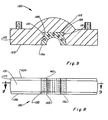
- FIGURES 8 and 9 A modified form of the improved ram front packer of the present invention is shown in FIGURES 8 and 9 as packer 120 which includes backing portion 122 with face recess 124 and insert portions 126.
- Backing portion 122 is substantially the same as backing portion 36.
- Face recess 124 has re-entrant portions 128 and lips 130 of insert portion 126 fit tightly therein.
- Backing portion 122 includes elastomeric body 132 and upper and lower plates 134 and 136.
- Insert portion 126 includes elastomeric body 138 with upper and lower plates 140 and 142 which are spaced apart by stems 144. Stems 144 are secured to plates 140 and 142.
- Stems 144 provide additional stability to insert 126 when its inner surface is spaced substantially inward from the forward portions 106 and 108 of ram body 24. Also if it is desired to close the rams and support a string thereon it is preferable that packer 120 be used so that additional support strength is available to support the string.
Abstract
Description
- Blowout preventers have.long been used in maintaining control of oil and gas wells during drilling. Usually several units are used in one stack. This allows blind rams and different size pipe rams to be available in a single stack. After many uses under pressure blind rams and pipe rams may require that the front packings be changed.
- Most pipe rams are now designed to seal on one specific size of drill pipe, tubing, or casing. When drilling conditions require changing pipe sizes, e.g., from a 4 inch to a 3 1/2 inch drill pipe, standard procedure now is to change the complete set of pipe rams, or change the complete front packings.
- Prior blowout preventers have utilized front packings which are removable from the ram. This allows the ram to be used in a variety of applications. In most cases the major portion of the front packing is undamaged but the entire packing is replaced whenever its central pipe sealing portion is damaged.
- In prior stripping rams, an arcuate insert of reduced friction material has been used between the upper and lower plates to line the pipe receiving recess. A structure of this type is shown in U.S. Pat. No. 4,323,256.
- Another type of insert used in the front face of a ram front pac..er is the resilient retainer which defines a part of a groove into which a plastic sealant is injected as shown in U.S. Pat. No. 4,227,543.
- The present invention relates to an improved ram-type blowout preventer in which the ram front packing includes a backing portion and a replaceable face sealing or insert portion which are inter-engageable with each other so that when installed in the ram packer slot they are held together.
- An object of the present invention is to provide an improved ram-type blowout preventer which can be used as a blind ram blowout preventer or as a pipe ram blowout preventer for different pipe sizes without the expense of carrying a complete stock of ram front packers.
- Another object is to provide an improved ram front packer for a ram-type blowout preventer which after wear or damage can be inexpensively replaced.
- A further object is to provide .an improved ram front packer for a ram-type blowout preventer allowing an improved seal without sacrificing the strength and integrity of the front packer.
- These and other objects and advantages of the present invention are hereinafter set forth and explained with respect to the drawings wherein:
- FIGURE 1 is an elevation view partly in section of the improved ram-type blowout preventer of the present invention.
- FIGURE 2 is an enlarged view, partly in section, of one side of the blowout preventer shown in FIGURE 1.
- FIGURE 3 is a front elevation view of the ram front packing of the improved blowout preventer of the present invention.
- FIGURE 4 is a sectional view of the improved ram front packing taken along line 4-4 in FIGURE 3.
- FIGURE 5.is an exploded view of the complete ram assembly of the improved blowout preventer.
- FIGURE 6 is a sectional view of another embodiment of the improved ram front packing.
- FIGURE 7 is a front view of the ram of the improved blowout preventer with the packing of FIGURE 6 installed.
- FIGURE 8 is a front elevation view of another modified form of the improved ram front packing of the present invention.
- FIGURE 9 is a sectional view taken along line 9-9 in FIGURE 8.
-
Blowout preventer 10 is shown havingbody 12 through whichcentral bore 14 extends with opposedaligned guideways 16 extending outward frombore 14 as shown in FIGURES 1 and 2. Ram 18 is moved inguideway 16 bysuitable actuator 20 connected toram 18 by connectingrod 22. Ram 18 includesbody 24,ram front packing 26 positioned infront recess 28 and packingseal 30 which is positioned in agroove 32 inbody 24 that extends along the sides and across the top ofbody 24 and seal 30 seals againstram front packing 26 as shown in FIGURE 5 and seals against the interior of theguideway 16. - Ram
front packing 26 is best seen in FIGURES 3 and 4 and includesbacking portion 36 andreplaceable insert portion 38.Backing portion 36 includes elastomeric material orbody 40 with upper andlower reinforcing plates Backing portion 36 includesrecess 46 in its forward face 48.Recess 46 includes re-entrantportions 50. Insertportion 38 includes elastomeric material orbody 52 with upper andlower retaining plates 54 and 56 bonded thereto or integrally formed therein. In plan view insertportion 38 has a shape which fits closely intorecess 46 withlips 58 fitting closely intore-entrant portions 50 ofrecess 46. Retainingplates 54 and 56 are substantially flush with reinforcingplates Lugs 60 extend from the rear of packing 26 and are used to secure packing 26 intorecess 28 inram 18. Insertportion 38 includespipe receiving recess 62 of a preselected size in its front face 64. If desiredrecess 62 may be omitted ifpacker 26 is to be in the form of a blind ram as indicated by the dashed lines in FIGURE 4. - With
insert 38 positioned in engagement withrecess 46 inbacking portion 36 and packer 26 secured inrecess 28, packer 26 functions as other ram packers with several advantages not present in other packers. Simply by changinginsert 38,front packer 26 can be used as a packer for a blind ram or a pipe ram in a variety of sizes. Also since most of the wear in a pipe ram is in the portion engaging the pipe, particularly in stripping operations, the replacement ofinsert 38 provides a substantially new ram front packer insert for a fraction of the cost of an entire ram front packer. Additionally different hardness of elastomeric materials can be used inbacking portion 36 and ininsert portion 38 to allow better sealing against pipe without sacrificing the strength and integrity of the packer. Additionally instripping operations body 52 ofinsert 38 may be made of a low coefficient of friction material such as Teflon as manufactured by DuPont Company. - An alternate form of ram front packer is
packer 66 as shown in FIGURES 5 and 6. Packer 66 includesbacking portion 68 andreplaceable insert portion 70. Insert 70 traverses essentially the entire front ofpacker 66 and includes elastomeric material orbody 72 with upper and lower retaining plates 74 and 76 bonded thereto or integrally formed therein.Backing portion 68 includescentral recess 78,side recesses Central recess 78 is formed in the forward face 84.Recess 78 includesre-entrant portion 86 andside recesses re-entrant portions 88. In plan view, as shown in FIGURE 5,insert portion 70 has a shape which fits closely intocentral recess 78,side recesses backing portion 68 withlips 90 ofcentral portion 92 andlips 94 ofside portions 96 fitting closely intore-entrant portions plates insert portion 70 are substantially flush with the reinforcing plates ofbacking portion 68. It is to be understood thatpacker 66 is similar topacker 26 except as described above. - As shown in FIGURE 7, when installed in
ram body 24 ramfront packer 26 andinsert 38 are retained against vertical movement by upper andlower portions ram body 24.Pins 110 of packingseal 30 insert intoslots 112 oflugs 60 to retainram front packer 26 against forward movement. Insert 38 is retained against forward movement bylips 58 fitting closely intore-entrant portions 50. - A modified form of the improved ram front packer of the present invention is shown in FIGURES 8 and 9 as
packer 120 which includesbacking portion 122 withface recess 124 and insertportions 126.Backing portion 122 is substantially the same asbacking portion 36.Face recess 124 hasre-entrant portions 128 andlips 130 ofinsert portion 126 fit tightly therein.Backing portion 122 includeselastomeric body 132 and upper andlower plates 134 and 136.Insert portion 126 includeselastomeric body 138 with upper andlower plates 140 and 142 which are spaced apart by stems 144. Stems 144 are secured toplates 140 and 142. Stems 144 provide additional stability to insert 126 when its inner surface is spaced substantially inward from theforward portions ram body 24. Also if it is desired to close the rams and support a string thereon it is preferable thatpacker 120 be used so that additional support strength is available to support the string.
Claims (12)
Priority Applications (1)
| Application Number | Priority Date | Filing Date | Title |
|---|---|---|---|
| AT83108521T ATE41972T1 (en) | 1982-09-16 | 1983-08-30 | JAW BLOW-OUT PREVENTION. |
Applications Claiming Priority (2)
| Application Number | Priority Date | Filing Date | Title |
|---|---|---|---|
| US419080 | 1982-09-16 | ||
| US06/419,080 US4541639A (en) | 1982-09-16 | 1982-09-16 | Ram-type blowout preventer with improved ram front packer |
Publications (3)
| Publication Number | Publication Date |
|---|---|
| EP0103786A2 true EP0103786A2 (en) | 1984-03-28 |
| EP0103786A3 EP0103786A3 (en) | 1985-06-05 |
| EP0103786B1 EP0103786B1 (en) | 1989-04-05 |
Family
ID=23660715
Family Applications (1)
| Application Number | Title | Priority Date | Filing Date |
|---|---|---|---|
| EP83108521A Expired EP0103786B1 (en) | 1982-09-16 | 1983-08-30 | Ram-type blowout preventer |
Country Status (8)
| Country | Link |
|---|---|
| US (1) | US4541639A (en) |
| EP (1) | EP0103786B1 (en) |
| JP (1) | JPS5972394A (en) |
| AT (1) | ATE41972T1 (en) |
| CA (1) | CA1203159A (en) |
| DE (1) | DE3379549D1 (en) |
| MX (1) | MX156732A (en) |
| NO (1) | NO165309C (en) |
Cited By (1)
| Publication number | Priority date | Publication date | Assignee | Title |
|---|---|---|---|---|
| WO2016122916A1 (en) * | 2015-01-27 | 2016-08-04 | National Oilwell Varco, L.P. | Compound blowout preventer seal and method of using same |
Families Citing this family (17)
| Publication number | Priority date | Publication date | Assignee | Title |
|---|---|---|---|---|
| US4703938A (en) * | 1986-02-10 | 1987-11-03 | Fox Allan J | Seal for ram type blowout preventor |
| US4825948A (en) * | 1987-03-16 | 1989-05-02 | Carnahan David A | Remotely variable multiple bore ram system and method |
| US5127623A (en) * | 1991-10-07 | 1992-07-07 | Petro-Flex Rubber Products, Inc. | Inner seal for ram-type blowout preventer |
| US5251870A (en) * | 1992-05-26 | 1993-10-12 | H & H Rubber, Inc. | Blowout preventer ram packer and wear insert |
| US5333832A (en) * | 1993-10-04 | 1994-08-02 | Bartholomew Leroy E | Blowout preventer with removable packer |
| US5405467A (en) * | 1993-08-09 | 1995-04-11 | Hydril Company | Rubber riveting of molded parts |
| US5622371A (en) * | 1996-01-11 | 1997-04-22 | Angelo; Lawrence F. | Stuffing box with improved packing rings and method |
| US5603481A (en) * | 1996-01-24 | 1997-02-18 | Cooper Cameron Corporation | Front packer for ram-type blowout preventer |
| CA2355002C (en) * | 2001-08-13 | 2009-07-07 | Quinn Holtby | Modular catch pan for wellheads and a method of use of the same |
| US7017881B2 (en) * | 2002-12-04 | 2006-03-28 | Petroleum Elastomers, Inc | Blowout preventer ram packer and wear insert |
| US9777546B2 (en) * | 2011-10-20 | 2017-10-03 | Cameron International Corporation | Ram packer extraction tool |
| US20140183382A1 (en) * | 2012-12-31 | 2014-07-03 | Hydril Usa Manufacturing Llc | Dual compound variable ram packer |
| US9238950B2 (en) * | 2014-01-10 | 2016-01-19 | National Oilwell Varco, L.P. | Blowout preventer with packer assembly and method of using same |
| US10087698B2 (en) * | 2015-12-03 | 2018-10-02 | General Electric Company | Variable ram packer for blowout preventer |
| USD1006593S1 (en) * | 2017-11-16 | 2023-12-05 | Worldwide Oilfield Machine, Inc | Ram packer |
| CN108180012A (en) * | 2017-12-21 | 2018-06-19 | 黄明道 | Deepwater drilling platform IBOP valves and preventer joint pressure test tool and pressure-measuring method |
| US11761285B2 (en) | 2021-07-28 | 2023-09-19 | Benton Frederick Baugh | Method for controlling pressure in blowout preventer ram seals |
Citations (4)
| Publication number | Priority date | Publication date | Assignee | Title |
|---|---|---|---|---|
| US2527068A (en) * | 1946-05-03 | 1950-10-24 | Cameron Iron Works Inc | Ram packing |
| US4323256A (en) * | 1980-04-30 | 1982-04-06 | Hydril Company | Front packer seal for ram blowout preventer |
| US4332367A (en) * | 1980-05-02 | 1982-06-01 | Nl Industries, Inc. | Blowout preventer having a variable ram seal |
| US4398729A (en) * | 1982-12-20 | 1983-08-16 | Bowen Tools, Inc. | Blowout preventer inner ram seal assembly |
Family Cites Families (6)
| Publication number | Priority date | Publication date | Assignee | Title |
|---|---|---|---|---|
| CA594175A (en) * | 1960-03-08 | The Guiberson Corporation | Well blowout preventer | |
| US1466137A (en) * | 1922-05-29 | 1923-08-28 | Ottumwa Iron Works | Bushing for car wheels |
| US2194255A (en) * | 1938-11-23 | 1940-03-19 | Cameron Iron Works Inc | Blowout preventer |
| GB681312A (en) * | 1950-05-23 | 1952-10-22 | Cameron Iron Works Inc | Improvements in or relating to packing assemblies for blow-out preventors |
| US2912214A (en) * | 1954-03-01 | 1959-11-10 | Cameron Iron Works Inc | Blowout preventer |
| US3692316A (en) * | 1970-12-21 | 1972-09-19 | Bowen Tools Inc | Wireline blowout preventer |
-
1982
- 1982-09-16 US US06/419,080 patent/US4541639A/en not_active Expired - Lifetime
-
1983
- 1983-08-30 AT AT83108521T patent/ATE41972T1/en not_active IP Right Cessation
- 1983-08-30 DE DE8383108521T patent/DE3379549D1/en not_active Expired
- 1983-08-30 EP EP83108521A patent/EP0103786B1/en not_active Expired
- 1983-09-07 CA CA000436216A patent/CA1203159A/en not_active Expired
- 1983-09-09 MX MX198667A patent/MX156732A/en unknown
- 1983-09-14 JP JP58170525A patent/JPS5972394A/en active Granted
- 1983-09-15 NO NO833326A patent/NO165309C/en unknown
Patent Citations (4)
| Publication number | Priority date | Publication date | Assignee | Title |
|---|---|---|---|---|
| US2527068A (en) * | 1946-05-03 | 1950-10-24 | Cameron Iron Works Inc | Ram packing |
| US4323256A (en) * | 1980-04-30 | 1982-04-06 | Hydril Company | Front packer seal for ram blowout preventer |
| US4332367A (en) * | 1980-05-02 | 1982-06-01 | Nl Industries, Inc. | Blowout preventer having a variable ram seal |
| US4398729A (en) * | 1982-12-20 | 1983-08-16 | Bowen Tools, Inc. | Blowout preventer inner ram seal assembly |
Cited By (2)
| Publication number | Priority date | Publication date | Assignee | Title |
|---|---|---|---|---|
| WO2016122916A1 (en) * | 2015-01-27 | 2016-08-04 | National Oilwell Varco, L.P. | Compound blowout preventer seal and method of using same |
| US9441443B2 (en) | 2015-01-27 | 2016-09-13 | National Oilwell Varco, L.P. | Compound blowout preventer seal and method of using same |
Also Published As
| Publication number | Publication date |
|---|---|
| JPS5972394A (en) | 1984-04-24 |
| EP0103786B1 (en) | 1989-04-05 |
| DE3379549D1 (en) | 1989-05-11 |
| EP0103786A3 (en) | 1985-06-05 |
| NO833326L (en) | 1984-03-19 |
| US4541639A (en) | 1985-09-17 |
| NO165309B (en) | 1990-10-15 |
| MX156732A (en) | 1988-09-28 |
| CA1203159A (en) | 1986-04-15 |
| ATE41972T1 (en) | 1989-04-15 |
| NO165309C (en) | 1991-01-30 |
| JPH0373712B2 (en) | 1991-11-22 |
Similar Documents
| Publication | Publication Date | Title |
|---|---|---|
| US4541639A (en) | Ram-type blowout preventer with improved ram front packer | |
| US7354026B2 (en) | Unitary blade seal for a shearing blind ram in a ram type blowout preventer | |
| US4341264A (en) | Wellhead shearing apparatus | |
| US6158505A (en) | Blade seal for a shearing blind ram in a ram type blowout preventer | |
| US7243713B2 (en) | Shear/seal ram assembly for a ram-type blowout prevention system | |
| US5515916A (en) | Blowout preventer | |
| US4550895A (en) | Ram construction for oil well blow out preventer apparatus | |
| US4323256A (en) | Front packer seal for ram blowout preventer | |
| EP0140490B1 (en) | Ram-type blowout preventer and packer therefor | |
| US6974135B2 (en) | Variable bore ram | |
| US5603481A (en) | Front packer for ram-type blowout preventer | |
| EP0439896A1 (en) | Variable bore packer for a ram type blowout preventer | |
| EP0902161A2 (en) | Improved variable bore ram packer for a ram type blowout preventer | |
| US5127623A (en) | Inner seal for ram-type blowout preventer | |
| US2746710A (en) | Blowout preventer and ram therefor | |
| US5251870A (en) | Blowout preventer ram packer and wear insert | |
| US20060144586A1 (en) | Shearing blind ram assembly with a fish pocket | |
| US4508312A (en) | Ram-type blowout preventer | |
| US4703938A (en) | Seal for ram type blowout preventor | |
| US5333832A (en) | Blowout preventer with removable packer | |
| US20040079909A1 (en) | Side retainer plate for variable bore ram packer for a ram type blowout preventer | |
| US3897039A (en) | Variable inside diameter blowout preventer | |
| US5180137A (en) | Ram type blowout preventer having improved ram front packings | |
| US9963951B2 (en) | Annular blowout preventer | |
| US3821838A (en) | Apparatus for removing and replacing blowout preventer seals in situ |
Legal Events
| Date | Code | Title | Description |
|---|---|---|---|
| PUAI | Public reference made under article 153(3) epc to a published international application that has entered the european phase |
Free format text: ORIGINAL CODE: 0009012 |
|
| AK | Designated contracting states |
Designated state(s): AT BE CH DE FR GB IT LI LU NL SE |
|
| 17P | Request for examination filed |
Effective date: 19840914 |
|
| PUAL | Search report despatched |
Free format text: ORIGINAL CODE: 0009013 |
|
| AK | Designated contracting states |
Designated state(s): AT BE CH DE FR GB IT LI LU NL SE |
|
| 17Q | First examination report despatched |
Effective date: 19860910 |
|
| GRAA | (expected) grant |
Free format text: ORIGINAL CODE: 0009210 |
|
| AK | Designated contracting states |
Kind code of ref document: B1 Designated state(s): AT BE CH DE FR GB IT LI LU NL SE |
|
| PG25 | Lapsed in a contracting state [announced via postgrant information from national office to epo] |
Ref country code: SE Effective date: 19890405 Ref country code: LI Effective date: 19890405 Ref country code: IT Free format text: LAPSE BECAUSE OF FAILURE TO SUBMIT A TRANSLATION OF THE DESCRIPTION OR TO PAY THE FEE WITHIN THE PRESCRIBED TIME-LIMIT;WARNING: LAPSES OF ITALIAN PATENTS WITH EFFECTIVE DATE BEFORE 2007 MAY HAVE OCCURRED AT ANY TIME BEFORE 2007. THE CORRECT EFFECTIVE DATE MAY BE DIFFERENT FROM THE ONE RECORDED. Effective date: 19890405 Ref country code: CH Effective date: 19890405 Ref country code: BE Effective date: 19890405 Ref country code: AT Effective date: 19890405 |
|
| REF | Corresponds to: |
Ref document number: 41972 Country of ref document: AT Date of ref document: 19890415 Kind code of ref document: T |
|
| REF | Corresponds to: |
Ref document number: 3379549 Country of ref document: DE Date of ref document: 19890511 |
|
| ET | Fr: translation filed | ||
| REG | Reference to a national code |
Ref country code: CH Ref legal event code: PL |
|
| PG25 | Lapsed in a contracting state [announced via postgrant information from national office to epo] |
Ref country code: LU Free format text: LAPSE BECAUSE OF NON-PAYMENT OF DUE FEES Effective date: 19890831 |
|
| PLBE | No opposition filed within time limit |
Free format text: ORIGINAL CODE: 0009261 |
|
| STAA | Information on the status of an ep patent application or granted ep patent |
Free format text: STATUS: NO OPPOSITION FILED WITHIN TIME LIMIT |
|
| 26N | No opposition filed | ||
| PGFP | Annual fee paid to national office [announced via postgrant information from national office to epo] |
Ref country code: GB Payment date: 19910717 Year of fee payment: 9 |
|
| PGFP | Annual fee paid to national office [announced via postgrant information from national office to epo] |
Ref country code: FR Payment date: 19910822 Year of fee payment: 9 |
|
| PGFP | Annual fee paid to national office [announced via postgrant information from national office to epo] |
Ref country code: DE Payment date: 19910828 Year of fee payment: 9 |
|
| PGFP | Annual fee paid to national office [announced via postgrant information from national office to epo] |
Ref country code: NL Payment date: 19910831 Year of fee payment: 9 |
|
| PG25 | Lapsed in a contracting state [announced via postgrant information from national office to epo] |
Ref country code: GB Effective date: 19920830 |
|
| PG25 | Lapsed in a contracting state [announced via postgrant information from national office to epo] |
Ref country code: NL Effective date: 19930301 |
|
| NLV4 | Nl: lapsed or anulled due to non-payment of the annual fee | ||
| GBPC | Gb: european patent ceased through non-payment of renewal fee |
Effective date: 19920830 |
|
| PG25 | Lapsed in a contracting state [announced via postgrant information from national office to epo] |
Ref country code: FR Effective date: 19930430 |
|
| PG25 | Lapsed in a contracting state [announced via postgrant information from national office to epo] |
Ref country code: DE Effective date: 19930501 |
|
| REG | Reference to a national code |
Ref country code: FR Ref legal event code: ST |