EP0241836B1 - Drip irrigation apparatus - Google Patents
Drip irrigation apparatus Download PDFInfo
- Publication number
- EP0241836B1 EP0241836B1 EP87105065A EP87105065A EP0241836B1 EP 0241836 B1 EP0241836 B1 EP 0241836B1 EP 87105065 A EP87105065 A EP 87105065A EP 87105065 A EP87105065 A EP 87105065A EP 0241836 B1 EP0241836 B1 EP 0241836B1
- Authority
- EP
- European Patent Office
- Prior art keywords
- outer tube
- drip irrigation
- irrigation apparatus
- insert
- pathway
- Prior art date
- Legal status (The legal status is an assumption and is not a legal conclusion. Google has not performed a legal analysis and makes no representation as to the accuracy of the status listed.)
- Expired - Lifetime
Links
- 230000002262 irrigation Effects 0.000 title claims abstract description 42
- 238000003973 irrigation Methods 0.000 title claims abstract description 42
- 230000037361 pathway Effects 0.000 claims abstract description 53
- XLYOFNOQVPJJNP-UHFFFAOYSA-N water Substances O XLYOFNOQVPJJNP-UHFFFAOYSA-N 0.000 claims description 52
- 238000004891 communication Methods 0.000 claims description 3
- 230000002452 interceptive effect Effects 0.000 claims description 3
- 238000000034 method Methods 0.000 claims description 3
- 238000000465 moulding Methods 0.000 claims description 2
- 230000008569 process Effects 0.000 claims description 2
- 239000012528 membrane Substances 0.000 description 9
- 239000000463 material Substances 0.000 description 4
- 238000010276 construction Methods 0.000 description 3
- 238000004519 manufacturing process Methods 0.000 description 2
- ZAKOWWREFLAJOT-CEFNRUSXSA-N D-alpha-tocopherylacetate Chemical compound CC(=O)OC1=C(C)C(C)=C2O[C@@](CCC[C@H](C)CCC[C@H](C)CCCC(C)C)(C)CCC2=C1C ZAKOWWREFLAJOT-CEFNRUSXSA-N 0.000 description 1
- 244000292411 Excoecaria agallocha Species 0.000 description 1
- 238000005452 bending Methods 0.000 description 1
- 230000015572 biosynthetic process Effects 0.000 description 1
- 230000007423 decrease Effects 0.000 description 1
- 238000001125 extrusion Methods 0.000 description 1
- 230000003993 interaction Effects 0.000 description 1
- 238000012986 modification Methods 0.000 description 1
- 230000004048 modification Effects 0.000 description 1
- 230000000717 retained effect Effects 0.000 description 1
- 238000007789 sealing Methods 0.000 description 1
Images
Classifications
-
- A—HUMAN NECESSITIES
- A01—AGRICULTURE; FORESTRY; ANIMAL HUSBANDRY; HUNTING; TRAPPING; FISHING
- A01G—HORTICULTURE; CULTIVATION OF VEGETABLES, FLOWERS, RICE, FRUIT, VINES, HOPS OR SEAWEED; FORESTRY; WATERING
- A01G25/00—Watering gardens, fields, sports grounds or the like
- A01G25/02—Watering arrangements located above the soil which make use of perforated pipe-lines or pipe-lines with dispensing fittings, e.g. for drip irrigation
- A01G25/023—Dispensing fittings for drip irrigation, e.g. drippers
-
- A—HUMAN NECESSITIES
- A01—AGRICULTURE; FORESTRY; ANIMAL HUSBANDRY; HUNTING; TRAPPING; FISHING
- A01G—HORTICULTURE; CULTIVATION OF VEGETABLES, FLOWERS, RICE, FRUIT, VINES, HOPS OR SEAWEED; FORESTRY; WATERING
- A01G25/00—Watering gardens, fields, sports grounds or the like
- A01G25/006—Tubular drip irrigation dispensers mounted coaxially within water feeding tubes
-
- Y—GENERAL TAGGING OF NEW TECHNOLOGICAL DEVELOPMENTS; GENERAL TAGGING OF CROSS-SECTIONAL TECHNOLOGIES SPANNING OVER SEVERAL SECTIONS OF THE IPC; TECHNICAL SUBJECTS COVERED BY FORMER USPC CROSS-REFERENCE ART COLLECTIONS [XRACs] AND DIGESTS
- Y02—TECHNOLOGIES OR APPLICATIONS FOR MITIGATION OR ADAPTATION AGAINST CLIMATE CHANGE
- Y02A—TECHNOLOGIES FOR ADAPTATION TO CLIMATE CHANGE
- Y02A40/00—Adaptation technologies in agriculture, forestry, livestock or agroalimentary production
- Y02A40/10—Adaptation technologies in agriculture, forestry, livestock or agroalimentary production in agriculture
- Y02A40/22—Improving land use; Improving water use or availability; Controlling erosion
Definitions
- the present invention relates to a drip irrigation apparatus comprising a continuous outer tube extending along a longitudinal axis and a plurality of flow rate determining inserts fixedly joined to said outer tube at desired locations therealong interiorly of said outer tube, said flow rate determining inserts each defining a water inlet communicating with the interior of said outer tube, flow rate determining means, flow controlling means, and a water outlet chamber in engagement with said outer tube, a water exit from said outlet chamber being defined by perforation of said outer tube at said water outlet chamber, wherein said flow-controlling means is responsive to pressure within said outer tube.
- the drip irrigation apparatus of the invention can be formed within a continuous extruded tube.
- a number of types of continuous tube type drippers are known.
- One type comprises a cylindrical body having a pressure reducing pathway formed on the outer surface thereof, which pathway engages the inner surface of a continuous tube extruded thereabout. It has also been proposed to insert an intermediate layer of material interposed between the pressure reducing pathway of the cylindrical body and the continuous tube.
- Another type of continuous tube dripper employs self-contained flow controlled dripper elements which are attached to the inner wall of a continuous tube and provided with outlet apertures therethrough.
- Drip irrigation apparatus comprising a continuous outer tube extending along a longitudinal axis and a plurality of flow rate determining inserts fixedly joined to the outer tube at desired locations therealong interiorly of the outer tube, the flow rate determining inserts each defining a water inlet communicating with the interior of the outer tube, flow rate determining means, flow controlling means, a water outlet chamber which extends over a significant portion of the circumference of the outer tube in engagement therewith, and a water exit from the outlet chamber being defined by perforation of the outer tube at the water outlet chamber are known from DE-B-2 902 007 and also from DE-A-2 548 670.
- the flow rate determining means and the flow controlling means in these apparatus is provided by a restricted pathway which only acts as passive controlling means insofar as its constant flow resistance only causes a generally reduced flow rate, i.e., if the pressure increases this known flow rate determining means and flow controlling means provides a correspondingly increased flow rate. However, it is desired to maintain a substantially constant flow rate when the pressure increases.
- an irrigation pipe water outlet which has two membranes forming two chambers connected to water and air supplies.
- This irrigation pipe water outlet consists of a first membrane displaceable into the pipe for restricting the cross section thereof and a casing with a membrane control element for actuating the first membrane.
- the membrane control element is equipped with a second membrane dividing the inside of the casing into two chambers.
- One of these chambers is connected by a pipe to the irrigation pipe, while the other chamber is connected by a tube to an air supply pipe with a non-return valve.
- This type of water flow control has the disadvantage that it requires a source of pressurized air and a control apparatus for controlling the pressure of the air supplied to the aforesaid air chamber of the irrigation pipe water outlet.
- a drip irrigation apparatus of the type mentioned in the beginning is known from US-A-4 210 287.
- This drip irrigation apparatus has a flow controlling means which is responsive to the pressure within the outer tube.
- This flow controlling means comprises a resiliently flexible membrane of generally rectangular shape which is arranged on one side of a generally flat and rectangular base structure and which defines one side of the flow rate determining means and a cavity like recess into which the flow rate determining means opens.
- the flow rate determining means and the cavity like recess there is provided the water outlet chamber which defined on its one side by the inner wall of the outer tube. This water outlet chamber communicates by a bore with the cavity like recess.
- the shape of the water outlet chamber is that of a shallow elongated well which has an elongated nearly rectangular shape and is coextensive with the membrane. This has the disadvantage that the accuracy of the perforation location, i.e. the location of the water exit from the outlet chamber can affect the operation of the flow controlling means.
- the present invention seeks to overcome disadvantages of prior art continuous tube type drip irrigation apparatus and to provide a continuous tube type drip irrigation device which is relatively easy and inexpensive to manufacture.
- a drip irrigation apparatus of the type mentioned in the beginning, which is characterized in that the water outlet chamber is axially displaced from said flow controlling means, whereby accuracy of perforation location within said water outlet chamber cannot affect operation of said flow controllin means.
- a preferred embodiment of this drip irrigation apparatus is characterized in that the flow rate determining means comprises a flow rate determining pathway located on a portion of a surface, which surface does not extend along the entire circumference of the inner surface of said outer tube and the water outlet chamber extends over a signifcant portion of the circumference of the outer tube in engagement therewith.
- the flow rate determining insert comprises bendable fingers associated with the insert for assisting positioning thereof in the outer tube without interfering with substantial flattening thereof for shipping purposes.
- the pressure reducing pathway surface is configured as a cylindrical section having a different radius than the corresponding inner surface of the outer tube.
- annular rib associated with said insert and disposed in sealing engagement with the inner surface of the outer tube along at least most of its circumference.
- Another embodiment is characterized in that the water outlet chamber extends over at least half of the circumference of the outer tube or that the water outlet chamber extends over the entire circumference of the outer tube or that the water outlet chamber extends over at least one third of the circumference of the outer tube.
- the flow rate determining pathway is defined solely by the insert and according to another embodiment the flow rate determining pathway is defined jointly by the insert and by the inner wall of the outer tube.
- the flow rate determining means and the flow controlling means comprise a resilient element mounted onto the insert to define therewith a flow rate determining and flow controlling chamber in communication with the water inlet and the water outlet chamber and including a pressure reducing pathway defined by at least one of the resilient element and the insert.
- a flow controlling pathway communicating with the pressure reducing pathway.
- the flow controlling means comprise resilient means which are held in place by cooperation between the insert and the continuous outer tube.
- the flow controlling means comprise resilient means and means for prestressing said resilient means.
- the flow controlling means comprise resilient means and cover means covering part of said resilient means.
- the flow determining means or pathway comprises a pressure reducing pathway which is defined on a curved surface which forms part of a cylindrical surface.
- Said curved surface can have a radius greater than the inner radius of said outer tube intermediate the inserts.
- a further preferred embodiment is characterized in that said flow controlling means are formed entirely integrally with said insert as a single unit in a single molding process.
- the flow controlled pressure reducing insert comprises a generally cylindrical element having pressure reducing means formed along a portion of the circumference thereof and a water inlet to the pressure reducing means, securing means associated with the cylindrical element on either side of the water inlet, a pressure responsive element disposed in the securing means and separating the volume adjacent the water inlet from the remainder of the interior of the cylindrical element, thereby defining a pressure controlled water passageway communicating with the water inlet.
- the securing means comprise slits formed in the cylindrical element.
- the pressure reducing pathway defines a portion of a surface of revolution which is arranged for attachment onto the interior wail or an outer tube, the insert spanning less than half of the circumference of the outer tube, thereby permitting substantial flattening of the tube for shipping purposes.
- the insert may also comprise bendable extension fingers for assisting in proper placement of the insert but without interfering with the flattening of the tube.
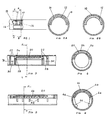
- the illustrated drip irrigation comprises a continuous outer tube 10, typically formed by extrusion and in which are disposed at predetermined intervals inserts 12 which provide output flow control as desired ,such that the high pressure water supply within the tube 10 results in a relatively low pressure output at a desired flow rate.
- the insert 12 comprises a pressure reducing pathway 14 comprising a plurality of back and forth bends and sub paths or any other suitable configuration and a water outlet chamber 16 communicating with the outlet of the pressure reducing pathway 14. It is a particular feature of the present invention that the water outlet chamber 16 extends across a significant portion of the circumference of the outer tube 10. This feature enables outlet holes 18 to be formed in the outer tube 10 without precise attention to the rotational orientation of the insert therein. It may be appreciated that if chamber 16 extends over at least one-half of the circumference of the tube, as illustrated, the hole making apparatus need have only 50% radial accuracy in order to provide a properly positioned hole. Thus many of the advantages of a full cylindrical insert are provided without the costs for materials that would be required in such a case.
- the insert illustrated in Figs. 1, 2A and 2B defines the pressure reducing pathway in cooperation with the inner wall of the outer tube, this need not necessarily be the case.
- the pressure reducing pathway may be defined solely by the insert, and thus not in cooperation with the outer tube.
- Figs. 3 and 4 illustrate drip irrigation apparatus having features of another embodiment of the invention in which a pressure reducing path 20 is associated with a plurality of annular ribs 22 which support the path 20 within an outer tube 24.
- an insert 26 comprises the pressure reducing path 20 integrally formed with annular ribs 22 along each side thereof.
- Transverse slits 28 formed in each of the ribs define an outlet conduit communicating between the outlet of the pressure reducing path to a pair of outlet chambers 30 which extend around the entire circumference of the insert and in engagement with the entire circumference of the inner surface of the outer tube 24.
- This construction which uses somewhat more material than that illustrated in Fig. 1, provides a whole circumference water outlet chamber 30 as well as secure positioning of the insert in the tube 24 by means of ribs 22.
- a single rib 22 and only a single water outer chamber 30 may be provided.
- inlets to the pressure reducing pathways illustrated in Figs. 1, 2A , 2B, 3 and 4 are not seen in the Figures but may be positioned where desired for supply of water from the interior of the outer tube to the pressure reducing pathway.
- pressure reducing pathway is employed herein, the invention also encompasses the use of a flow reducing pathway or other device which need not necessarily reduce pressure, or not reduce pressure as its major objective. Nevertheless all of these devices shall be collectively referred to herein as "pressure reducing pathways”.
- Figs. 5 and 6 illustrate drip irrigation apparatus of the type described hereinabove in connection with Fig. 1 with certain modifications.
- the insert 40 shown in Figs. 5 and 6 extends along less than half of the circumference of the outer tube.
- bendable extension fingers 42 along both sides of the insert 40 for assisting in positioning of the insert in the outer tube 44.
- Transverse nicks or cuts 46 may be made in the fingers 42 at their junction with the insert 40 to encourage bending thereof when the outer tube is compressed for flattening thereof. It is appreciated that extension fingers 42 may also be applied to the insert illustrated in Figs. 1, 2A and 2B.
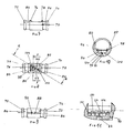
- Figs. 7 to 11 illustrate an insert constructed and operative in accordance with an embodiment of the invention, which insert is designed to be disposed at predetermined intervals in a continuous outer tube, such as tube 10, described hereinabove in connection with Fig. 1.
- the pressure reducing pathway is defined in cooperation with the inner wall of the outer tube 10
- the pressure reducing pathway is defined in cooperation with a pressure responsive element.
- Figs. 7 to 11 thus illustrate an insert 70 of generally cylindrical configuration and defining first and second outer annular ribs 72 and 74 and first and second inner ribs 76 and 78. Ribs 76 and 78 are joined along all but the top of the insert and define longitudinal edges 80 and 82. Disposed between respective first inner and outer ribs 72 and 76 is an annular recess which defines an outlet chamber 84. A similar outlet chamber 86 is defined between second inner and outer ribs 74 and 78 in a similar annular recess.
- Outlet chambers 84 and 86 receive a water output via a recessed conduit 88 which is formed on the underside of insert 70 and which communicates with a transverse aperture 90 extending from a pressure controlled pressure and/or flow controlling chamber 92.
- Pressure controlled pressure and/or flow controlling chamber 92 is separated from the remainder of the interior of the insert 70 by means of an elastic element 94, typically formed of rubber or a similar material, which functions as a pressure responsive element and is retained in slots 96 and 98 formed in the interior of the insert as seen in Fig. 10.
- a pressure controlled pressure and/or flow reducing pathway 100 is defined as part of chamber 92 in the surface 102 of the insert which faces the elastic element 94. This pathway may be of any desired shape and configuration, as desired and suitable. It is noted that the pathway 100 extends from a water inlet 101 extending from the edge of chamber 92 into a pressure and/or flow controlling volume 104, into communication with an aperture 90.
- the chamber 92 including pathway 100 may be wholly or partially defined by the elastic element 94.
- elastic element 94 effectively seals chamber 92 from the remainder of the interior of the insert, which is maintained at line pressure, except at inlet 101. Elastic element 94 thus acts as a pressure sensitive controller of the flow through pathway 100. As the line pressure increases, element 94 is displaced increasingly onto pathway 100 and volume 104, thus reducing its cross sectional area and limiting the flow therethrough. As the line pressure decreases, element 94 is increasingly separated from pathway 100 and volume 104, defining a greater effective cross sectional area for water flow through pathway 100.
- the elastic element 94 may be rigidify where it overlies the pathway 100, or to provide a cover over this portion, in order to reduce or eliminate the influence of the line pressure on the cross sectional area of the pathway 100.
- the pathway 100 may be located away from the elastic element.
- the apparatus of Figs. 7 to 11 may alterantively be connected to the outlet of the pressure reducing pathway.
- the pressure reducing pathway may comprise a small aperture, typically of a radius of between one tenth to one hundredth of a millimeter, formed in the elastic element 94.
- the interaction between the elastic element 94 and the pathway 100 may be reduced or eliminated in one of a number of ways.
- a cover member (not shown) may be provided overlying the elastic element 94 where it overlies the pathway 100.
- the elastic clement 94 may not extend over the pathway 100. Where a cover member is provided it may serve to provide prestressing of the elastic element 94 in the area of volume 104.
- the elastic element 94 may be prestressed over its entire area covering both the pathway 100 and the volume 104.
- the elastic element 94 as well as any securing member or cover member associated therewith may be held in place by means of the outer tube which surrounds the insert.
Landscapes
- Life Sciences & Earth Sciences (AREA)
- Engineering & Computer Science (AREA)
- Water Supply & Treatment (AREA)
- Environmental Sciences (AREA)
- Soil Sciences (AREA)
- Catching Or Destruction (AREA)
- Infusion, Injection, And Reservoir Apparatuses (AREA)
Priority Applications (1)
| Application Number | Priority Date | Filing Date | Title |
|---|---|---|---|
| AT87105065T ATE70945T1 (de) | 1981-07-15 | 1982-07-14 | Tropfbewaesserungsvorrichtung. |
Applications Claiming Priority (2)
| Application Number | Priority Date | Filing Date | Title |
|---|---|---|---|
| IL63341 | 1981-07-15 | ||
| IL6334181A IL63341A (en) | 1981-07-15 | 1981-07-15 | Drip irrigation apparatus |
Related Parent Applications (1)
| Application Number | Title | Priority Date | Filing Date |
|---|---|---|---|
| EP82106308.8 Division | 1982-07-14 |
Publications (2)
| Publication Number | Publication Date |
|---|---|
| EP0241836A1 EP0241836A1 (en) | 1987-10-21 |
| EP0241836B1 true EP0241836B1 (en) | 1992-01-02 |
Family
ID=11052778
Family Applications (2)
| Application Number | Title | Priority Date | Filing Date |
|---|---|---|---|
| EP87105065A Expired - Lifetime EP0241836B1 (en) | 1981-07-15 | 1982-07-14 | Drip irrigation apparatus |
| EP19820106308 Expired EP0070036B1 (en) | 1981-07-15 | 1982-07-14 | Drip irrigation apparatus |
Family Applications After (1)
| Application Number | Title | Priority Date | Filing Date |
|---|---|---|---|
| EP19820106308 Expired EP0070036B1 (en) | 1981-07-15 | 1982-07-14 | Drip irrigation apparatus |
Country Status (10)
| Country | Link |
|---|---|
| US (2) | US4519546A (pt) |
| EP (2) | EP0241836B1 (pt) |
| AT (2) | ATE70945T1 (pt) |
| AU (3) | AU555471B2 (pt) |
| DE (2) | DE3279094D1 (pt) |
| ES (1) | ES272916Y (pt) |
| GR (1) | GR76188B (pt) |
| IL (1) | IL63341A (pt) |
| PT (1) | PT75243B (pt) |
| ZA (1) | ZA825043B (pt) |
Families Citing this family (43)
| Publication number | Priority date | Publication date | Assignee | Title |
|---|---|---|---|---|
| IL63341A (en) * | 1981-07-15 | 1996-09-12 | Naan Mech Works | Drip irrigation apparatus |
| IL76553A (en) * | 1985-10-03 | 1993-01-31 | Naan Mech Works | Drip irrigation apparatus |
| CH678476A5 (pt) * | 1986-04-11 | 1991-09-30 | Maillefer Sa | |
| FR2605492B1 (fr) * | 1986-10-28 | 1989-05-26 | Testa Jean Pierre | Distributeur d'eau sans pression pour arrosage goutte a goutte |
| US4846406A (en) * | 1987-12-04 | 1989-07-11 | Wade Manufacturing Co. | Micro flow control valve for irrigation systems and method |
| US4850531A (en) * | 1988-02-01 | 1989-07-25 | James Hardie Irrigation, Inc. | Drip emitter |
| DK722388A (da) * | 1988-12-23 | 1990-06-24 | Dgt Volmatic As | Drypvandingsanlaeg og drypdyse |
| IL93255A (en) * | 1990-02-02 | 1997-03-18 | Plastro Gvat | Drip irrigation lines |
| IL95972A (en) * | 1990-10-12 | 1993-03-15 | Naan Irrigation Systems | Method and apparatus for producing pipes for drip irrigation |
| US5236130A (en) * | 1991-03-15 | 1993-08-17 | Lego M. Lemelshtrich Ltd. | Drip irrigation apparatus |
| IL101071A (en) * | 1992-02-26 | 1997-09-30 | Naan Irrigation Systems | Drip irrigation apparatus |
| US5400973A (en) * | 1993-07-30 | 1995-03-28 | Cohen; Amir | Pressure responsive regulated flow restrictor useful for drip irrigation |
| US5688072A (en) * | 1995-12-14 | 1997-11-18 | Micro Irrigation Technologies, Inc. | Agricultural drip tape |
| US5836326A (en) * | 1997-05-08 | 1998-11-17 | Clearly Canadian Beverage Corporation | Bead cleansing system |
| IL121967A (en) | 1997-10-14 | 2001-06-14 | Hydro Plan Eng Ltd | Irrigation output unit |
| IL129817A (en) * | 1999-05-06 | 2002-12-01 | Plassim Tech Plastics Works | Method for producing an irrigation pipeline with inner emitters |
| US6736337B2 (en) | 2002-02-08 | 2004-05-18 | The Toro Company | Pressure compensating drip irrigation hose |
| US20060151363A1 (en) * | 2005-01-07 | 2006-07-13 | Claudiu-Ioan Ratiu | Modular disc filter with integrated and automated self-flushing operator |
| IL167015A (en) | 2005-02-21 | 2013-01-31 | Plastro Irrigation Systems Ltd | In-line system of mini sprinklers and method and apparatus for making same |
| US8302887B2 (en) * | 2005-03-31 | 2012-11-06 | Rain Bird Corporation | Drip emitter |
| US7648085B2 (en) * | 2006-02-22 | 2010-01-19 | Rain Bird Corporation | Drip emitter |
| US8628032B2 (en) * | 2008-12-31 | 2014-01-14 | Rain Bird Corporation | Low flow irrigation emitter |
| US20100282873A1 (en) * | 2009-05-06 | 2010-11-11 | Mattlin Jeffrey L | Drip Emitter and Methods of Assembly and Mounting |
| US10440903B2 (en) | 2012-03-26 | 2019-10-15 | Rain Bird Corporation | Drip line emitter and methods relating to same |
| US9485923B2 (en) | 2012-03-26 | 2016-11-08 | Rain Bird Corporation | Elastomeric emitter and methods relating to same |
| US9877440B2 (en) | 2012-03-26 | 2018-01-30 | Rain Bird Corporation | Elastomeric emitter and methods relating to same |
| US20130248622A1 (en) | 2012-03-26 | 2013-09-26 | Jae Yung Kim | Drip line and emitter and methods relating to same |
| US9872444B2 (en) | 2013-03-15 | 2018-01-23 | Rain Bird Corporation | Drip emitter |
| USD811179S1 (en) | 2013-08-12 | 2018-02-27 | Rain Bird Corporation | Emitter part |
| US10285342B2 (en) | 2013-08-12 | 2019-05-14 | Rain Bird Corporation | Elastomeric emitter and methods relating to same |
| US10631473B2 (en) | 2013-08-12 | 2020-04-28 | Rain Bird Corporation | Elastomeric emitter and methods relating to same |
| US9883640B2 (en) | 2013-10-22 | 2018-02-06 | Rain Bird Corporation | Methods and apparatus for transporting elastomeric emitters and/or manufacturing drip lines |
| US10330559B2 (en) | 2014-09-11 | 2019-06-25 | Rain Bird Corporation | Methods and apparatus for checking emitter bonds in an irrigation drip line |
| US10375904B2 (en) | 2016-07-18 | 2019-08-13 | Rain Bird Corporation | Emitter locating system and related methods |
| WO2018140772A1 (en) | 2017-01-27 | 2018-08-02 | Rain Bird Corporation | Pressure compensation members, emitters, drip line and methods relating to same |
| US10232388B2 (en) | 2017-03-08 | 2019-03-19 | NaanDanJain Irrigation Ltd. | Multiple orientation rotatable sprinkler |
| US10626998B2 (en) | 2017-05-15 | 2020-04-21 | Rain Bird Corporation | Drip emitter with check valve |
| EP3706554B1 (en) * | 2017-11-08 | 2024-07-24 | N-Drip Ltd. | Method and system for irrigation at stabilized pressure |
| USD883048S1 (en) | 2017-12-12 | 2020-05-05 | Rain Bird Corporation | Emitter part |
| US11985924B2 (en) | 2018-06-11 | 2024-05-21 | Rain Bird Corporation | Emitter outlet, emitter, drip line and methods relating to same |
| CN109699456B (zh) * | 2019-02-26 | 2021-02-19 | 任华红 | 一种具有水压调节功能的便捷型滴灌设备 |
| US11452269B2 (en) | 2019-06-14 | 2022-09-27 | The Toro Company | Rail tuned pressure responsive irrigation emitter |
| US12207599B2 (en) | 2021-10-12 | 2025-01-28 | Rain Bird Corporation | Emitter coupler and irrigation system |
Citations (1)
| Publication number | Priority date | Publication date | Assignee | Title |
|---|---|---|---|---|
| US4210287A (en) * | 1977-11-24 | 1980-07-01 | Hydro-Plan Engineering Ltd. | Drip irrigation system |
Family Cites Families (12)
| Publication number | Priority date | Publication date | Assignee | Title |
|---|---|---|---|---|
| US3873030A (en) * | 1972-07-17 | 1975-03-25 | Jaime Suhagun Barragan | One-piece drip irrigation device |
| US3779468A (en) * | 1972-07-21 | 1973-12-18 | L Spencer | Trickle irrigation system |
| US3870236A (en) * | 1973-03-14 | 1975-03-11 | Sahagun Barragan Jaime | Dripping irrigation tubing |
| US3797754A (en) * | 1973-06-21 | 1974-03-19 | L Spencer | Continuous tube trickle irrigation |
| IL45211A (en) * | 1974-07-08 | 1976-11-30 | Eckstein Gershon | Irrigation pipe with dripper units and method of its manufacture |
| US4058257A (en) * | 1974-12-05 | 1977-11-15 | Lloyd Spencer | Irrigation emitter |
| US3981452A (en) * | 1975-02-10 | 1976-09-21 | Gershon Eckstein | Irrigation pipes with dripper units and method of its manufacture |
| US4385727A (en) * | 1975-04-22 | 1983-05-31 | Lloyd Spencer | Irrigation emitter tube |
| US4022384A (en) * | 1975-12-08 | 1977-05-10 | Hancor, Inc. | Irrigation tubing |
| DE2902007C2 (de) * | 1979-01-19 | 1980-12-11 | Reifenhaeuser Kg, 5210 Troisdorf | Kunststoff-Rohrleitung mit einer Einrichtung für die Tropfbewässerung |
| IL56948A0 (en) * | 1979-03-26 | 1979-05-31 | Bron D | Flow rate regulator |
| IL63341A (en) * | 1981-07-15 | 1996-09-12 | Naan Mech Works | Drip irrigation apparatus |
-
1981
- 1981-07-15 IL IL6334181A patent/IL63341A/en active IP Right Review Request
-
1982
- 1982-07-08 US US06/396,409 patent/US4519546A/en not_active Expired - Lifetime
- 1982-07-12 GR GR68723A patent/GR76188B/el unknown
- 1982-07-14 DE DE8282106308T patent/DE3279094D1/de not_active Expired
- 1982-07-14 AT AT87105065T patent/ATE70945T1/de not_active IP Right Cessation
- 1982-07-14 EP EP87105065A patent/EP0241836B1/en not_active Expired - Lifetime
- 1982-07-14 PT PT75243A patent/PT75243B/pt unknown
- 1982-07-14 AT AT82106308T patent/ATE37765T1/de not_active IP Right Cessation
- 1982-07-14 DE DE8787105065T patent/DE3280387D1/de not_active Expired - Lifetime
- 1982-07-14 EP EP19820106308 patent/EP0070036B1/en not_active Expired
- 1982-07-14 AU AU86012/82A patent/AU555471B2/en not_active Expired
- 1982-07-14 ES ES1982272916U patent/ES272916Y/es not_active Expired
- 1982-07-15 ZA ZA825043A patent/ZA825043B/xx unknown
-
1985
- 1985-05-01 US US06/729,194 patent/US4728042A/en not_active Expired - Lifetime
-
1986
- 1986-12-24 AU AU67007/86A patent/AU6700786A/en not_active Abandoned
-
1990
- 1990-12-14 AU AU68072/90A patent/AU639513B2/en not_active Ceased
Patent Citations (1)
| Publication number | Priority date | Publication date | Assignee | Title |
|---|---|---|---|---|
| US4210287A (en) * | 1977-11-24 | 1980-07-01 | Hydro-Plan Engineering Ltd. | Drip irrigation system |
Non-Patent Citations (1)
| Title |
|---|
| Derwent Publications Ltd., London P 13 * |
Also Published As
| Publication number | Publication date |
|---|---|
| EP0070036B1 (en) | 1988-10-12 |
| GR76188B (pt) | 1984-08-03 |
| AU6700786A (en) | 1987-04-30 |
| ZA825043B (en) | 1983-05-25 |
| EP0241836A1 (en) | 1987-10-21 |
| AU6807290A (en) | 1991-02-21 |
| IL63341A (en) | 1996-09-12 |
| US4519546A (en) | 1985-05-28 |
| DE3279094D1 (en) | 1988-11-17 |
| ES272916U (es) | 1983-11-01 |
| EP0070036A2 (en) | 1983-01-19 |
| AU8601282A (en) | 1984-01-19 |
| DE3280387D1 (de) | 1992-02-13 |
| AU639513B2 (en) | 1993-07-29 |
| ATE70945T1 (de) | 1992-01-15 |
| IL63341A0 (en) | 1995-07-31 |
| PT75243B (en) | 1984-10-29 |
| US4728042A (en) | 1988-03-01 |
| ATE37765T1 (de) | 1988-10-15 |
| EP0070036A3 (en) | 1984-09-12 |
| PT75243A (en) | 1982-08-01 |
| ES272916Y (es) | 1984-05-01 |
| AU555471B2 (en) | 1986-09-25 |
Similar Documents
| Publication | Publication Date | Title |
|---|---|---|
| EP0241836B1 (en) | Drip irrigation apparatus | |
| US4210287A (en) | Drip irrigation system | |
| EP0467386B1 (en) | Drip irrigation emitters | |
| US4502631A (en) | Trickle irrigation unit | |
| US10455780B2 (en) | In line button drip emitter | |
| US4613080A (en) | Multiple outlet trickle irrigation unit | |
| US5111996A (en) | Incremental pressure-compensating drip irrigation emitter | |
| US5294058A (en) | Regulated drip irrigation emitter | |
| US4209133A (en) | Drip level irrigation emitter unit | |
| US4430020A (en) | Drip irrigation hose | |
| US4366926A (en) | Irrigation emitter unit | |
| US5400973A (en) | Pressure responsive regulated flow restrictor useful for drip irrigation | |
| EP0268418B1 (en) | Flow regulating device | |
| US4077883A (en) | Reverse osmosis system with automatic pressure relief valve | |
| EP0024670A2 (en) | A self-regulating constant output nozzle for a supply line | |
| EP0160299A2 (en) | Continuous tube emitter | |
| GB2133860A (en) | Fluid flow control device particularly useful as a drip irrigation emitter | |
| EP0081529B1 (en) | Pressure-regulated drip feed device | |
| US4193711A (en) | Flow control valve for subsurface irrigation system | |
| US4074434A (en) | Pressure-responsive speed control for dental handpieces | |
| JPS62524B2 (pt) | ||
| AU8580482A (en) | Pressure-regulated drip feed device | |
| JPS61141871U (pt) |
Legal Events
| Date | Code | Title | Description |
|---|---|---|---|
| PUAI | Public reference made under article 153(3) epc to a published international application that has entered the european phase |
Free format text: ORIGINAL CODE: 0009012 |
|
| AC | Divisional application: reference to earlier application |
Ref document number: 70036 Country of ref document: EP |
|
| AK | Designated contracting states |
Kind code of ref document: A1 Designated state(s): AT BE CH DE FR GB IT LI NL SE |
|
| 17P | Request for examination filed |
Effective date: 19871203 |
|
| 17Q | First examination report despatched |
Effective date: 19890620 |
|
| RAP3 | Party data changed (applicant data changed or rights of an application transferred) |
Owner name: NAAN IRRIGATION SYSTEMS |
|
| GRAA | (expected) grant |
Free format text: ORIGINAL CODE: 0009210 |
|
| AC | Divisional application: reference to earlier application |
Ref document number: 70036 Country of ref document: EP |
|
| AK | Designated contracting states |
Kind code of ref document: B1 Designated state(s): AT BE CH DE FR GB IT LI NL SE |
|
| REF | Corresponds to: |
Ref document number: 70945 Country of ref document: AT Date of ref document: 19920115 Kind code of ref document: T |
|
| ITF | It: translation for a ep patent filed | ||
| REF | Corresponds to: |
Ref document number: 3280387 Country of ref document: DE Date of ref document: 19920213 |
|
| ET | Fr: translation filed | ||
| PGFP | Annual fee paid to national office [announced via postgrant information from national office to epo] |
Ref country code: CH Payment date: 19920603 Year of fee payment: 11 |
|
| PGFP | Annual fee paid to national office [announced via postgrant information from national office to epo] |
Ref country code: DE Payment date: 19920629 Year of fee payment: 11 |
|
| PGFP | Annual fee paid to national office [announced via postgrant information from national office to epo] |
Ref country code: GB Payment date: 19920630 Year of fee payment: 11 |
|
| PGFP | Annual fee paid to national office [announced via postgrant information from national office to epo] |
Ref country code: SE Payment date: 19920702 Year of fee payment: 11 |
|
| PGFP | Annual fee paid to national office [announced via postgrant information from national office to epo] |
Ref country code: AT Payment date: 19920727 Year of fee payment: 11 |
|
| PGFP | Annual fee paid to national office [announced via postgrant information from national office to epo] |
Ref country code: NL Payment date: 19920731 Year of fee payment: 11 |
|
| PGFP | Annual fee paid to national office [announced via postgrant information from national office to epo] |
Ref country code: BE Payment date: 19920805 Year of fee payment: 11 |
|
| PLBE | No opposition filed within time limit |
Free format text: ORIGINAL CODE: 0009261 |
|
| STAA | Information on the status of an ep patent application or granted ep patent |
Free format text: STATUS: NO OPPOSITION FILED WITHIN TIME LIMIT |
|
| 26N | No opposition filed | ||
| PG25 | Lapsed in a contracting state [announced via postgrant information from national office to epo] |
Ref country code: GB Effective date: 19930714 Ref country code: AT Effective date: 19930714 |
|
| PG25 | Lapsed in a contracting state [announced via postgrant information from national office to epo] |
Ref country code: SE Effective date: 19930715 |
|
| PG25 | Lapsed in a contracting state [announced via postgrant information from national office to epo] |
Ref country code: LI Effective date: 19930731 Ref country code: CH Effective date: 19930731 Ref country code: BE Effective date: 19930731 |
|
| BERE | Be: lapsed |
Owner name: NAAN IRRIGATION SYSTEMS Effective date: 19930731 |
|
| PG25 | Lapsed in a contracting state [announced via postgrant information from national office to epo] |
Ref country code: NL Effective date: 19940201 |
|
| GBPC | Gb: european patent ceased through non-payment of renewal fee |
Effective date: 19930714 |
|
| NLV4 | Nl: lapsed or anulled due to non-payment of the annual fee | ||
| REG | Reference to a national code |
Ref country code: CH Ref legal event code: PL |
|
| PG25 | Lapsed in a contracting state [announced via postgrant information from national office to epo] |
Ref country code: DE Effective date: 19940401 |
|
| EUG | Se: european patent has lapsed |
Ref document number: 87105065.4 Effective date: 19940210 |
|
| PGFP | Annual fee paid to national office [announced via postgrant information from national office to epo] |
Ref country code: FR Payment date: 20000727 Year of fee payment: 19 |
|
| PG25 | Lapsed in a contracting state [announced via postgrant information from national office to epo] |
Ref country code: FR Free format text: LAPSE BECAUSE OF NON-PAYMENT OF DUE FEES Effective date: 20020329 |
|
| REG | Reference to a national code |
Ref country code: FR Ref legal event code: ST |