EP0241782B1 - Methode und Vorrichtung für die Messung des Unterschiedes der Geschwindigkeit beim Bandgiessen - Google Patents
Methode und Vorrichtung für die Messung des Unterschiedes der Geschwindigkeit beim Bandgiessen Download PDFInfo
- Publication number
- EP0241782B1 EP0241782B1 EP87104486A EP87104486A EP0241782B1 EP 0241782 B1 EP0241782 B1 EP 0241782B1 EP 87104486 A EP87104486 A EP 87104486A EP 87104486 A EP87104486 A EP 87104486A EP 0241782 B1 EP0241782 B1 EP 0241782B1
- Authority
- EP
- European Patent Office
- Prior art keywords
- activated
- measuring
- measuring region
- speed
- casting drum
- Prior art date
- Legal status (The legal status is an assumption and is not a legal conclusion. Google has not performed a legal analysis and makes no representation as to the accuracy of the status listed.)
- Expired
Links
- 238000005266 casting Methods 0.000 title claims description 71
- 238000000034 method Methods 0.000 title claims description 12
- 238000005259 measurement Methods 0.000 title claims description 4
- 230000002093 peripheral effect Effects 0.000 claims description 29
- 239000004020 conductor Substances 0.000 claims description 13
- 230000003287 optical effect Effects 0.000 claims description 12
- 239000000155 melt Substances 0.000 description 6
- 230000001419 dependent effect Effects 0.000 description 5
- 238000012545 processing Methods 0.000 description 3
- 238000011161 development Methods 0.000 description 2
- 230000018109 developmental process Effects 0.000 description 2
- 230000001105 regulatory effect Effects 0.000 description 2
- 239000000956 alloy Substances 0.000 description 1
- 229910045601 alloy Inorganic materials 0.000 description 1
- 238000005275 alloying Methods 0.000 description 1
- 230000015572 biosynthetic process Effects 0.000 description 1
- 238000001816 cooling Methods 0.000 description 1
- 230000008878 coupling Effects 0.000 description 1
- 238000010168 coupling process Methods 0.000 description 1
- 238000005859 coupling reaction Methods 0.000 description 1
- 238000006073 displacement reaction Methods 0.000 description 1
- 238000004519 manufacturing process Methods 0.000 description 1
- 239000000203 mixture Substances 0.000 description 1
- 238000012856 packing Methods 0.000 description 1
- 238000003825 pressing Methods 0.000 description 1
- 238000007711 solidification Methods 0.000 description 1
- 230000008023 solidification Effects 0.000 description 1
Images
Classifications
-
- G—PHYSICS
- G01—MEASURING; TESTING
- G01P—MEASURING LINEAR OR ANGULAR SPEED, ACCELERATION, DECELERATION, OR SHOCK; INDICATING PRESENCE, ABSENCE, OR DIRECTION, OF MOVEMENT
- G01P3/00—Measuring linear or angular speed; Measuring differences of linear or angular speeds
- G01P3/42—Devices characterised by the use of electric or magnetic means
- G01P3/56—Devices characterised by the use of electric or magnetic means for comparing two speeds
Definitions
- the invention relates to a method for speed difference measurement in strip casting according to the precharacterising part of Claim 1.
- the invention also refers to a device for carrying out the method.
- strip casting is meant the production of a cast strip or sheet by pressing a melt between an endless travelling belt and a casting drum, which belt, via the solidifying melt, makes contact with part of the periphery of the casting drum rotating along with the belt. Said part of the periphery represents the casting region. This casting region is continuously moved relative to an around the periphery of the drum during the casting process.
- Melt is fed continuously into the V-shaped cleft formed between the casting drum and the travelling belt tangentially entering the casting region.
- the belt leaves the casting drum tangentially at the end of the casting region and supports the cast strip.
- the thickness of the cast strip is determined by several factors, the most important being the following:
- the quality characteristics of the cast strip are also largely dependent on the above-mentioned factors.
- the quality of the cast strip is to a very large extent dependent on whether the peripheral speed of the casting drum and the speed of the belt are equal. There must be no slipping between the strip to be cast and the casting drum and between the strip and the travelling belt, respectively. If the respective speeds are different, the cast strip during the casting and solidification process will be subjected to internal stresses between the layer which makes contact with the drum and the layer which makes contact with the belt. The direction of this stress is dependent upon which speed is greater, the speed of the belt or the peripheral speed of the drum.
- the invention aims at developing a method and device for speed difference measurement in a strip casting process which makes possible a highly accurate measuring of the relative angular velocity between the casting drum and that part of the travelling belt which makes contact with the strip to be cast.
- a device for carrying out the method according to the invention is characterized by the features of Claim 4.
- the invention enables to detect and measure a possible speed difference between the peripheral speed of the casting drum and the speed of the travelling belt.
- the measuring values can hence be employed for regulating purposes, for example for obtaining an equality of speeds.
- the invention comprises the use of the travelling belt which, on one edge on its side facing the casting drum, is provided with a raster with a fixed width in the direction of travel of the belt.
- a number of measuring zones having the same widths as the rater on the travelling belt.
- Each measuring zone consists of or comprises one transducer mounted close to the periphery of the casting drum and directed towards the travelling belt.
- Each transducer consists of a plurality of optical conductors, radially opening out into the periphery of the casting drum, and a corresponding number of photocells.
- a peripheral measuring region with an extension equal to a fixed multiple of the width of the measuring zone is defined, for example as that part of the periphery of the casting drum which is covered by the travelling belt, that is, the casting region.
- a change of the number of activated photocells, increased or reduced, indicates that there is a relative speed between the belt and the periphery of the casting drum.
- the direction of the relative speed is determined by whether the number of active photocells has increased or reduced and whether the first or the last photocell is activated, and by an additional number of boundary conditions where are to be described below.
- the information obtained can then be utilized for regulating the respective drive means so that a practical, acceptable speed equality is attained.
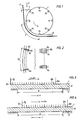
- Figure 1 shows schematically a device for strip casting. Between a casting drum 1 and an endless travelling belt 2 a melt 4 is continuously supplied at 3, solidifies in the casting region 5, and is cast into a strip 6.
- each measuring zone 7a-7h is evenly distributed along the periphery of the casting drum, each measuring zone comprising a transducer.
- the belt 2 On that side of the travelling belt 2 facing the casting drum 1 and on the edge of the belt positioned opposite of the edge of the casting drum 1 on which the measuring zones and the transducers are located, the belt 2 is provided with a raster pattern having alternately darker and lighter stripes.
- the extension of the raster strips in the travelling direction of the belt 2 is equal to the peripheral extension or width of the measuring zones.
- each transducer consists of a number of optical conductors and a corresponding number of photocells and covers the entire extension of the measuring zone. From a purely practical point of view, the transducer can be formed according to Figure 2. To obtain the desired resolution capacity, a relatively large number of photocells must be included in the transducer of each measuring zone. A good resolution capacity also requires that the peripheral extension of the measuring zones must be restricted. In practice this means that, from the view point of space, the photocells cannot be located directly at the periphery of the casting drum 1.
- optical conductors are therefore used which open out into the periphery of the casting drum 1 in the measuring zone, thus obtaining a considerably higher packing density of the light-sensitive elements.
- Figure 2 showing the transducer for measuring zone 7g according to Figure 1, a great number of optical conductors 8a ... 8n are placed in each measuring zone. Via these conductors, current signals are transmitted to the photocells 9a ... 9n, located inside the casting drum 1, for further signal processing.
- the belt 2 may be rastered with alternatively light and dark stripes with an extension in the travelling direction of the belt 2 of, for example, 1 mm.
- the peripheral extension of each measuring zone shall have the same width, that is, also 1 mm.
- Each measuring zone may, for example, be covered by 20 optical conductors, each one then having an extension of 0.05 mm in the peripheral direction.
- an overlap configuration between the measuring zone and the rastered belt 2 may have an appearance as illustrated in Figure 3.
- the first 17 photocells 9a-9n indicate, via the optical conductors, an overlap of 17/20 of 1 mm.
- the overlap configuration between the same transducer and the same raster stripe may have an appearance according to Figure 4. From this it is clear that the peripheral speed or angular speed of the casting drum 1 is somewhat greater than the corresponding speed of the belt 2, since the photocells of the transducer, via the optical conductors, will now determine that only the last 18 photocells are activated. Therefore, in total terms, a displacement amount to (3+2)/20 of the measuring zone, or in this case 0.25 mm, has taken place within the measuring region.
- a simple and classical device for determining which of the speeds-the speed of the belt or the peripheral speed of the drum-is the greater may consist of a tachometer mounted on a deflector roll for the travelling belt and a tachometer mounted on a shaft of the casting drum, possibly a tachometer mounted via a friction or other coupling connected to the periphery of the drum.
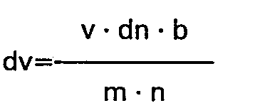
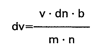
- dn is valid for the immediately preceding raster stripe upon entering the measuring region and for the immediately succeeding raster stripe when leaving the measuring region, respectively.
- the peripheral speed of the drum 1 is greater than the speed of the belt 2, that is, V drum >V belt when the following conditions, expressed in Boolean algebra, exist:
Landscapes
- Physics & Mathematics (AREA)
- General Physics & Mathematics (AREA)
- Continuous Casting (AREA)
Claims (6)

und daß die Umfangsgeschwindigkeit der Gießtrommel als kleiner als die Geschwindigkeit des umlaufenden Bandes angegeben wird, d.h., vbelt>vdrum, wenn die folgenden Bedingungen,, ausgedrückt in Bool'scher Algebra, bestehen:
und
Applications Claiming Priority (2)
| Application Number | Priority Date | Filing Date | Title |
|---|---|---|---|
| SE8601491 | 1986-04-03 | ||
| SE8601491A SE452806B (sv) | 1986-04-03 | 1986-04-03 | Forfarande och anordning for hastighetsdifferensmetning vid bandgjutning |
Publications (2)
| Publication Number | Publication Date |
|---|---|
| EP0241782A1 EP0241782A1 (de) | 1987-10-21 |
| EP0241782B1 true EP0241782B1 (de) | 1990-07-04 |
Family
ID=20364032
Family Applications (1)
| Application Number | Title | Priority Date | Filing Date |
|---|---|---|---|
| EP87104486A Expired EP0241782B1 (de) | 1986-04-03 | 1987-03-26 | Methode und Vorrichtung für die Messung des Unterschiedes der Geschwindigkeit beim Bandgiessen |
Country Status (5)
| Country | Link |
|---|---|
| US (1) | US4849917A (de) |
| EP (1) | EP0241782B1 (de) |
| JP (1) | JPS62238048A (de) |
| DE (1) | DE3763509D1 (de) |
| SE (1) | SE452806B (de) |
Families Citing this family (3)
| Publication number | Priority date | Publication date | Assignee | Title |
|---|---|---|---|---|
| US5338283A (en) * | 1992-10-09 | 1994-08-16 | E. I. Du Pont De Nemours And Company | Centrifuge rotor identification system |
| US20100131232A1 (en) * | 2008-11-21 | 2010-05-27 | Taylor Timothy M | Belt slip meter |
| JP5694481B1 (ja) * | 2013-10-30 | 2015-04-01 | ファナック株式会社 | 主軸とモータとの間の動力伝達部の異常を検出するモータ制御装置 |
Family Cites Families (4)
| Publication number | Priority date | Publication date | Assignee | Title |
|---|---|---|---|---|
| US3694712A (en) * | 1970-05-01 | 1972-09-26 | Xerox Corp | Speed control apparatus |
| CH637047A5 (de) * | 1978-12-29 | 1983-07-15 | Lauener W F Ag | Verfahren zur geschwindigkeitssteuerung einer bandgiess- und walzanlage und gemaess diesem verfahren gesteuerte anlage. |
| US4523624A (en) * | 1981-10-22 | 1985-06-18 | International Telephone And Telegraph Corporation | Cast ingot position control process and apparatus |
| JPH07108434B2 (ja) * | 1983-10-11 | 1995-11-22 | フオ−レスト エム パ−マ− | 金属ストリツプの連続鋳造方法および装置 |
-
1986
- 1986-04-03 SE SE8601491A patent/SE452806B/sv not_active IP Right Cessation
-
1987
- 1987-03-26 EP EP87104486A patent/EP0241782B1/de not_active Expired
- 1987-03-26 DE DE8787104486T patent/DE3763509D1/de not_active Expired - Fee Related
- 1987-03-27 US US07/030,447 patent/US4849917A/en not_active Expired - Fee Related
- 1987-04-01 JP JP62080851A patent/JPS62238048A/ja active Pending
Also Published As
| Publication number | Publication date |
|---|---|
| SE452806B (sv) | 1987-12-14 |
| DE3763509D1 (de) | 1990-08-09 |
| SE8601491D0 (sv) | 1986-04-03 |
| EP0241782A1 (de) | 1987-10-21 |
| SE8601491L (sv) | 1987-10-04 |
| US4849917A (en) | 1989-07-18 |
| JPS62238048A (ja) | 1987-10-19 |
Similar Documents
| Publication | Publication Date | Title |
|---|---|---|
| US5096044A (en) | Method and apparatus for monitoring the run of a belt | |
| US5978724A (en) | Vehicle control system | |
| KR930001545B1 (ko) | 회전 검출장치 | |
| US5125303A (en) | Combined jump conveyor and slicing machine | |
| EP0241782B1 (de) | Methode und Vorrichtung für die Messung des Unterschiedes der Geschwindigkeit beim Bandgiessen | |
| US4761610A (en) | Apparatus for determining the position of surface defects of a test objects with respect to an edge thereof | |
| US4727757A (en) | Ferro-magnetic foil for a torque sensor | |
| JPH11123952A (ja) | 先行車追従制御装置 | |
| US4309902A (en) | Method for continuously measuring steepness of defective flatness of metal strip during rolling | |
| US5356575A (en) | Method for controlling the trend of the change-over point | |
| US6313625B1 (en) | Magnetic rotary position sensing | |
| EP0068731B1 (de) | Überwachungs- und Steuereinrichtung für eine Schopfschere | |
| US5101880A (en) | Flaskless casting line | |
| US4179958A (en) | Method for shearing hot strips and device therefor | |
| US4790196A (en) | Sampler of particulate material on a moving belt | |
| JPS63302334A (ja) | 捻りトルク測定用軸 | |
| SU1295200A1 (ru) | Устройство дл измерени ширины движущегос материала | |
| JPH08298123A (ja) | 帯状電極板の連続切断方法 | |
| JPH0349817A (ja) | 帯状板材のサイドトリミング方法 | |
| JPS5744851A (en) | Eddy current type flaw detecting method and probe thereof | |
| SU596421A1 (ru) | Способ измерени устойчивости положени оси вращени круглых столов металлорежущих станков | |
| SU1041184A1 (ru) | Устройство дл сортировки листов по толщине в потоке | |
| JP4203799B2 (ja) | シート状物質のプロファイル測定方法 | |
| SU1036383A1 (ru) | Способ фотометрической сепарации кусковых материалов | |
| JPS57203961A (en) | Sensor for rotation velocity |
Legal Events
| Date | Code | Title | Description |
|---|---|---|---|
| PUAI | Public reference made under article 153(3) epc to a published international application that has entered the european phase |
Free format text: ORIGINAL CODE: 0009012 |
|
| AK | Designated contracting states |
Kind code of ref document: A1 Designated state(s): DE FR GB IT SE |
|
| 17P | Request for examination filed |
Effective date: 19880116 |
|
| 17Q | First examination report despatched |
Effective date: 19890407 |
|
| GRAA | (expected) grant |
Free format text: ORIGINAL CODE: 0009210 |
|
| AK | Designated contracting states |
Kind code of ref document: B1 Designated state(s): DE FR GB IT SE |
|
| REF | Corresponds to: |
Ref document number: 3763509 Country of ref document: DE Date of ref document: 19900809 |
|
| ET | Fr: translation filed | ||
| ITF | It: translation for a ep patent filed | ||
| ITTA | It: last paid annual fee | ||
| PLBE | No opposition filed within time limit |
Free format text: ORIGINAL CODE: 0009261 |
|
| STAA | Information on the status of an ep patent application or granted ep patent |
Free format text: STATUS: NO OPPOSITION FILED WITHIN TIME LIMIT |
|
| 26N | No opposition filed | ||
| PGFP | Annual fee paid to national office [announced via postgrant information from national office to epo] |
Ref country code: FR Payment date: 19911223 Year of fee payment: 6 |
|
| PGFP | Annual fee paid to national office [announced via postgrant information from national office to epo] |
Ref country code: GB Payment date: 19920316 Year of fee payment: 6 |
|
| PGFP | Annual fee paid to national office [announced via postgrant information from national office to epo] |
Ref country code: SE Payment date: 19920319 Year of fee payment: 6 |
|
| PGFP | Annual fee paid to national office [announced via postgrant information from national office to epo] |
Ref country code: DE Payment date: 19920430 Year of fee payment: 6 |
|
| PG25 | Lapsed in a contracting state [announced via postgrant information from national office to epo] |
Ref country code: GB Effective date: 19930326 |
|
| PG25 | Lapsed in a contracting state [announced via postgrant information from national office to epo] |
Ref country code: SE Effective date: 19930327 |
|
| GBPC | Gb: european patent ceased through non-payment of renewal fee |
Effective date: 19930326 |
|
| PG25 | Lapsed in a contracting state [announced via postgrant information from national office to epo] |
Ref country code: FR Effective date: 19931130 |
|
| PG25 | Lapsed in a contracting state [announced via postgrant information from national office to epo] |
Ref country code: DE Effective date: 19931201 |
|
| REG | Reference to a national code |
Ref country code: FR Ref legal event code: ST |
|
| EUG | Se: european patent has lapsed |
Ref document number: 87104486.3 Effective date: 19931008 |
|
| PG25 | Lapsed in a contracting state [announced via postgrant information from national office to epo] |
Ref country code: IT Free format text: LAPSE BECAUSE OF NON-PAYMENT OF DUE FEES Effective date: 20050326 |