EP0241684A2 - Procedure and arrangement for the adjusted assembly of optical components - Google Patents
Procedure and arrangement for the adjusted assembly of optical components Download PDFInfo
- Publication number
- EP0241684A2 EP0241684A2 EP87102821A EP87102821A EP0241684A2 EP 0241684 A2 EP0241684 A2 EP 0241684A2 EP 87102821 A EP87102821 A EP 87102821A EP 87102821 A EP87102821 A EP 87102821A EP 0241684 A2 EP0241684 A2 EP 0241684A2
- Authority
- EP
- European Patent Office
- Prior art keywords
- mounting
- solidifying substance
- chassis
- optical component
- thin intermediate
- Prior art date
- Legal status (The legal status is an assumption and is not a legal conclusion. Google has not performed a legal analysis and makes no representation as to the accuracy of the status listed.)
- Withdrawn
Links
Images


Classifications
-
- G—PHYSICS
- G01—MEASURING; TESTING
- G01J—MEASUREMENT OF INTENSITY, VELOCITY, SPECTRAL CONTENT, POLARISATION, PHASE OR PULSE CHARACTERISTICS OF INFRARED, VISIBLE OR ULTRAVIOLET LIGHT; COLORIMETRY; RADIATION PYROMETRY
- G01J3/00—Spectrometry; Spectrophotometry; Monochromators; Measuring colours
- G01J3/28—Investigating the spectrum
- G01J3/2803—Investigating the spectrum using photoelectric array detector
-
- C—CHEMISTRY; METALLURGY
- C09—DYES; PAINTS; POLISHES; NATURAL RESINS; ADHESIVES; COMPOSITIONS NOT OTHERWISE PROVIDED FOR; APPLICATIONS OF MATERIALS NOT OTHERWISE PROVIDED FOR
- C09J—ADHESIVES; NON-MECHANICAL ASPECTS OF ADHESIVE PROCESSES IN GENERAL; ADHESIVE PROCESSES NOT PROVIDED FOR ELSEWHERE; USE OF MATERIALS AS ADHESIVES
- C09J5/00—Adhesive processes in general; Adhesive processes not provided for elsewhere, e.g. relating to primers
-
- G—PHYSICS
- G02—OPTICS
- G02B—OPTICAL ELEMENTS, SYSTEMS OR APPARATUS
- G02B7/00—Mountings, adjusting means, or light-tight connections, for optical elements
- G02B7/003—Alignment of optical elements
-
- Y—GENERAL TAGGING OF NEW TECHNOLOGICAL DEVELOPMENTS; GENERAL TAGGING OF CROSS-SECTIONAL TECHNOLOGIES SPANNING OVER SEVERAL SECTIONS OF THE IPC; TECHNICAL SUBJECTS COVERED BY FORMER USPC CROSS-REFERENCE ART COLLECTIONS [XRACs] AND DIGESTS
- Y10—TECHNICAL SUBJECTS COVERED BY FORMER USPC
- Y10S—TECHNICAL SUBJECTS COVERED BY FORMER USPC CROSS-REFERENCE ART COLLECTIONS [XRACs] AND DIGESTS
- Y10S359/00—Optical: systems and elements
- Y10S359/90—Methods
Definitions
- the present invention relates to a method and arrangements for the adjusted assembly of an optical component in accordance with the preamble of claim 1.
- EP-A1-0 090 218 discloses a method and a device for adjusting and mounting optical components in optical devices.
- the optical component is connected to the device during the adjustment process only with an adjustment device not belonging to the device.
- the optical component or its holder is connected to the device by a liquid or pasty substance, which solidifies with a small change in volume.
- the optical component or its holder and the device are designed in such a way that a positive, non-positive or adhesive connection is formed between them.
- the adjustment device is removed.
- the optical component is sufficiently movable for the adjustment process, there must be sufficient distances between it or its holder and the device where the connection with the solidifying substance takes place.
- the resulting relatively large volumes or layer thicknesses mean that slight misalignments can again occur during the solidification process and that slight misalignments can occur in the fixed state due to the thermal expansion coefficients which are not exactly the same due to thermal influences.
- the known method therefore has the disadvantage that it does not meet very high requirements for adjustment accuracy and long-term stability with sufficient reliability.
- the present invention is therefore based on the object of improving the known method in such a way that, despite great freedom of movement during the adjustment, even extremely high demands on the adjustment accuracy and long-term stability are achieved.
- the object is achieved in that the fixation by the solidifying substance is divided into at least two mutually independent fixations and that the parts used for the fixations are designed and dimensioned such that optimum values for the volumes or Result in layer thicknesses.
- Optimal values result from the facts that in the case of very small volumes or layer thicknesses there are no sufficiently strong connections and that in the case of large volumes or layer thicknesses the temporal and thermal stability is not sufficiently reliable.
- the division of the fixation into several mutually independent fixations can correspond to the different translational and rotational movements during the adjustment. However, this does not have to be the case since the coordinate directions for adjustment and fixing are largely independent of one another.
- an optical component which itself or its mount or carrier plate has a round cross section, is arranged in a cylindrical cutout of a mounting plate with a joint for the solidifying substance, and the mounting plate is made of a thin intermediate layer on a support surface the solidifying substance.
- the arrangement of the optical component, which itself or its mount or carrier plate has a circular cross section, in the cylindrical cutout of the mounting plate can deviate conditions in the third direction. A rotation around all three spatial directions is also possible.
- the optical component or its mount or carrier plate is formed on its outer edge with a spherical surface, the radius of which is chosen to be the same as the radius of the cylindrical cutout in the mounting plate by the thickness of the joint for the solidifying substance and whose center lies in the middle of the optical component or its mount or carrier plate. This ensures that the cross section of the joint is independent of the rotations around those two spatial directions in which the mounting plate is displaceable.
- the cutout in the mounting plate and the outer border of the optical component or its mount or carrier plate can be formed in a spherical shell, whereby a rotation around all three spatial directions is possible with a uniform and constant cross-section of the joint for the solidifying substance.
- an optical component which itself or its mount or carrier plate has two mounting surfaces preferably arranged parallel to one another, is arranged between two mounting blocks with thin intermediate layers made of the solidifying substance and the mounting blocks are made with thin intermediate layers from the solidifying substance arranged on a support.
- the one Optical component which either itself or its mount or carrier plate has two mounting surfaces preferably arranged parallel to one another, is arranged between two first mounting blocks with thin intermediate layers made of the solidifying substance, in which the end faces of the first mounting blocks between two second mounting blocks with thin intermediate layers of the solidifying substance are arranged and in which the second mounting cuboids are arranged on a support surface or a chassis with thin intermediate layers of the solidifying substance.
- an optical component which either itself or its mount or carrier plate has a rear mounting surface, is arranged on a first cuboid mounting plate with a thin intermediate layer made of the solidifying substance; the first mounting plate is arranged with a side surface on a second cuboid mounting plate with a thin intermediate layer made of the solidifying substance and the second mounting plate is arranged with a side surface on a base plate or a chassis with a thin intermediate layer made of the solidifying substance.
- deviations of any size in all three spatial directions and rotations around all three spatial directions can be compensated for while maintaining the optimum layer thickness for the solidifying substance.
- the rotation around a spatial direction can be dispensed with and the optical component has a side mounting surface, as is the case with plane mirrors, for example, it is sufficient if the side mounting surface is arranged on a cuboid mounting plate with a thin intermediate layer made of the solidifying substance and if the mounting plate is arranged with a side surface on a base plate or a chassis with a thin intermediate layer made of the solidifying substance.
- compacted ceramic as the material for sockets, carrier plates, mounting cuboids, mounting plates and / or support surfaces or chassis, the composition of which is selected so that its coefficient of thermal expansion is equal to or approximately the same as that of the glass which the optical components are made.
- a diode line spectrometer consisting of the chassis (11), gap (12), concave grating (14) and diode line (13) exists.
- the gap, concave grating and diode row must be precisely adjusted to each other and permanently fixed.
- the adjustment (and exaggerated drawing) of the gap (12) is carried out in a known manner by adjusting the gap, for example etched into a metal plate, under observation with a measuring microscope, for example to the base of the chassis (11), and gluing it into a recess in the chassis.
- the concave grating (14) and the diode array (13) are initially only connected to the chassis (11) via manipulators and are precisely adjusted using these manipulators, as is known from EP-A1-0 090 218.
- the concave grating (14) and diode array (13) are then fixed using the arrangements shown in FIGS. 2 and 3.
- the concave grating is also designated (14). It has a pin (14a) on its back with which it is held by the manipulator.
- the outer border (14b) of the concave grating (14) sits with a narrow joint (22) in a cylindrical cutout of the mounting plate (23).
- This mounting plate is freely displaceable on the support surface (25) of the chassis (11) and therefore allows the concave grating (14) to be displaced in practically any size in the x and y directions.
- the concave grating (14) can be displaced in the z direction within the cylindrical cutout in the mounting plate (23). It can also be rotated as desired about the z direction and - depending on the width of the gap (22) - can also be rotated more or less about the x and y direction.
- the joint (22) between the concave grid (14) and the mounting plate (23) and the intermediate layer (24) between the mounting plate (23) and the support surface (25) are filled with the solidifying substance. This can be done before the adjustment if it is ensured that the adjustment process is complete before the solidification process begins. Otherwise, the mounting plate (23) with the appropriate amount of the solidifying substance is pushed over the outer border (14b) and pressed onto the support surface (25) when the adjustment of the concave grating (14).
- the volume or layer thickness can be brought to an optimal value by suitable dimensioning of the cylindrical cutout in the mounting plate (23) and by using suitable amounts of the solidifying substance.
- the outer border (14b) of the concave grating a curvature in the z direction, so that the outer border becomes a spherical cutout, the center of which also lies in the center of the concave grating (14) in the z direction.
- relatively large rotations of the concave grating (14) about the y and x axes are possible without the dimensions of the joint being changed.
- FIG 3 the assembly of the diode row is shown, which is glued to the support plate (31) below the plane of the drawing.
- the (not shown) connection pins of the diode line go through two slots (32), so that the first part of the electronics, which is expediently to be arranged as close as possible to the diode line, is arranged above the plane of the drawing.
- two threaded bushes (33) are glued into the support plate (31), into which stud bolts are screwed, which are also used for fastening the support plate (31) to the manipulator during adjustment and fixation.
- the carrier plate (31) has mounting surfaces (31a), on which, after adjustment, thin mounting layers (35) made of the solidifying substance are used to mount mounting blocks (36).
- the mounting cuboids (36) are also placed on the bearing surface (38) of the chassis (11) with thin intermediate layers (37) made of the solidifying substance.
- the carrier plate (31) does not lie on the support surface (38), but has a distance from it, so that it is not only shifted in the x and y directions and rotated about the z direction, but also in the z -Direction can be shifted and rotated around the x-direction. That way is one optimal adjustment possible to different areas of the spectrum generated by the concave grating (14).
- FIG. 4 shows an exemplary embodiment of an optical component (41), e.g. a mirror that can be moved in all three spatial directions and rotated around all three spatial directions.
- the optical component (41) connected to the manipulator via the pin (42) has two mounting surfaces (41a), on which, after adjustment with thin intermediate layers (43) made of the solidifying substance, first mounting cuboids (44) are placed.
- Second assembly cuboids (46) are placed on the end faces of these first assembly cuboids (44) with thin intermediate layers (45) made of the solidifying substance, which at the same time are placed on the support surface (48) with thin intermediate layers (47) made of the solidifying substance.
- FIGS. 5 and 6 show two further exemplary embodiments for the assembly of adjusted optical components.
- the optical component (51) of FIG. 5 can be, for example, a reflection grating, the rear surface of which is used as a mounting surface. It is held at its cylindrical boundary surface by a manipulator.
- a first cuboid mounting plate (53) is placed on the mounting surface with a thin intermediate layer (52) made of the solidifying substance.
- a second cuboid mounting plate (55) is placed, which at the same time has a side surface with a thin intermediate layer (56) made of the solidifying substance on the Base plate (57) is placed.
- the thin surface can be applied to the side surface (58) of the first mounting plate (53)
- a third mounting plate (not shown) is placed on the intermediate layer made of the solidifying substance, which is simultaneously placed on the base plate (57) with a side surface with an intermediate layer made of the solidifying substance.
- the optical component (51) can be moved in all three spatial directions x, y and z during the adjustment and rotated around all three spatial directions.
- a rotation around the z direction is not necessary in many cases, e.g. with plane mirrors.
- FIG. 6 a simpler embodiment is shown in which a side surface of the optical component (61) serves as a mounting surface.
- the cuboid mounting plate (65) is attached to this side surface, which at the same time has a side surface with a thin intermediate layer (66) made of the solidifying substance onto the base plate (67). is put on.
- a further mounting plate (not shown) can be attached to the side surface (68) of the optical component (61) with a thin intermediate layer made of the solidifying substance, which also has a side surface with a thin intermediate layer the solidifying substance is placed on the base plate (67).
- optical components do not have to be connected directly to the mounting blocks or mounting plate by the solidifying substance, but in all exemplary embodiments they can also first be used in sockets or mounted on mounting plates, in which case the sockets or mounting plates with the mounting blocks or Mounting plates are connected by the solidifying substance.
- carrier plates (31), mounting cuboids (36, 44, 46), mounting plate (23, 53, 55, 65) and / or contact surfaces (25, 38, 48, 57, 67) or chassis (11) compacted ceramic the composition of which is selected so that its coefficient of thermal expansion is equal to or approximately equal to that of the glass from which the optical components are made.
- UHU plus (R) can be used as the material for the solidifying substance, which is preferably processed in a layer thickness of approximately 0.1 mm.
Landscapes
- Physics & Mathematics (AREA)
- General Physics & Mathematics (AREA)
- Spectroscopy & Molecular Physics (AREA)
- Optics & Photonics (AREA)
- Chemical & Material Sciences (AREA)
- Organic Chemistry (AREA)
- Mounting And Adjusting Of Optical Elements (AREA)
- Prostheses (AREA)
Abstract
Für eine dauerhafte und beständige Fixierung von justierten optischen Bauteilen durch eine sich verfestigende Substanz wird die Fixierung auf mindestens zwei voneinander unabhängige Fixierungen (22, 24) aufgeteilt, wobei die für die Fixierungen verwendeten Teile (23) derart ausgebildet und dimensioniert sind, daß sich für die verfestigende Substanz optimale Volumina bzw. Schichtdicken ergeben. 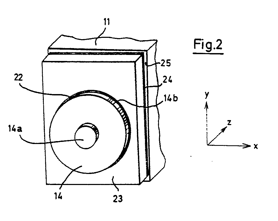
Description
Die vorliegende Erfindung betrifft ein Verfahren und Anordnungen zur justierten Montage eines optischen Bauteiles entsprechend dem Oberbegriff des Anspruches 1.The present invention relates to a method and arrangements for the adjusted assembly of an optical component in accordance with the preamble of claim 1.
Aus der EP-A1-0 090 218 ist ein Verfahren und eine Vorrichtung zum Justieren und Montieren von optischen Bauteilen in optischen Geräten bekannt. Dabei ist das optische Bauteil während des Justiervorganges mit dem Gerät nur mit einer nicht zum Gerät gehörenden Justiervorrichtung verbunden. Nach dem Justiervorgang wird das optische Bauteil oder seine Fassung mit dem Gerät durch eine flüssige oder pastenförmige Substanz verbunden, welche sich mit geringer Volumenänderung verfestigt. Das optische Bauteil oder seine Fassung und das Gerät sind hierfür derart ausgebildet, daß zwischen ihnen eine form-, kraft- oder haftschlüssige feste Verbindung entsteht. Nach der dauerhaften Fixierung des optischen Bauteiles wird die Justiervorrichtung entfernt.EP-A1-0 090 218 discloses a method and a device for adjusting and mounting optical components in optical devices. The optical component is connected to the device during the adjustment process only with an adjustment device not belonging to the device. After the adjustment process, the optical component or its holder is connected to the device by a liquid or pasty substance, which solidifies with a small change in volume. For this purpose, the optical component or its holder and the device are designed in such a way that a positive, non-positive or adhesive connection is formed between them. After the optical component has been permanently fixed, the adjustment device is removed.
Damit das optische Bauteil für den Justiervorgang ausreichend beweglich ist, müssen zwischen ihm bzw. seiner Fassung und dem Gerät genügend große Abstände auch dort sein, wo die Verbindung mit der sich verfestigenden Substanz erfolgt. Die dadurch bedingten relativ großen Volumina bzw. Schichtdicken führen dazu, daß beim Verfestigungsvorgang bereits wieder geringe Dejustierungen eintreten können und daß im fixierten Zustand infolge der nicht exakt gleichen thermischen Ausdehungskoeffizienten durch thermische Einflüsse geringe Dejustierungen entstehen können. Das bekannte Verfahren hat daher den Nachteil, daß es sehr hohen Anforderungen an Justiergenauigkeit und Langzeitstabilität nicht mit ausreichender Zuverlässigkeit entspricht.So that the optical component is sufficiently movable for the adjustment process, there must be sufficient distances between it or its holder and the device where the connection with the solidifying substance takes place. The resulting relatively large volumes or layer thicknesses mean that slight misalignments can again occur during the solidification process and that slight misalignments can occur in the fixed state due to the thermal expansion coefficients which are not exactly the same due to thermal influences. The known method therefore has the disadvantage that it does not meet very high requirements for adjustment accuracy and long-term stability with sufficient reliability.
Der vorliegenden Erfindung liegt daher die Aufgabe zugrunde, das bekannte Verfahren so zu verbessern, daß trotz großer Bewegungsfreiheit bei der Justierung selbst extrem hohe Anforderungen an die Justiergenauigkeit und Langzeitstabilität erreicht werden.The present invention is therefore based on the object of improving the known method in such a way that, despite great freedom of movement during the adjustment, even extremely high demands on the adjustment accuracy and long-term stability are achieved.
Die gestellte Aufgabe wird erfindungsgemäß dadurch gelöst, daß die Fixierung durch die sich verfestigende Substanz auf mindestens zwei voneinander unabhängige Fixierungen aufgeteilt wird und daß die für die Fixierungen verwendeten Teile derart ausgebildet und dimensioniert werden, daß sich für die verfestigende Substanz optimale Werte fur die Volumina bzw. Schichtdicken ergeben. Optimale Werte resultieren aus den Tatsachen, daß bei sehr geringen Volumina bzw. Schichtdicken keine ausreichend festen Verbindungen entstehen und daß bei großen Volumina bzw. Schichtdicken die zeitliche und thermische Stabilität nicht ausreichend zuverlässig ist. Die Aufteilung der Fixierung auf mehrere voneinander unabhängige Fixierungen kann den unterschiedlichen Translations- und Rotationsbewegungen bei der Justierung entsprechen. Das muß jedoch nicht der Fall sein, da die Koordinatenrichtungen für Justierung und Fixierung weitgehend unabhängig voneinander sind.The object is achieved in that the fixation by the solidifying substance is divided into at least two mutually independent fixations and that the parts used for the fixations are designed and dimensioned such that optimum values for the volumes or Result in layer thicknesses. Optimal values result from the facts that in the case of very small volumes or layer thicknesses there are no sufficiently strong connections and that in the case of large volumes or layer thicknesses the temporal and thermal stability is not sufficiently reliable. The division of the fixation into several mutually independent fixations can correspond to the different translational and rotational movements during the adjustment. However, this does not have to be the case since the coordinate directions for adjustment and fixing are largely independent of one another.
In einer vorteilhaften Ausführungsform ist ein optisches Bauteil, welches entweder selbst oder dessen Fassung bzw. Trägerplatte einen runden Querschnitt hat, in einem zylinderförmigen Ausschnitt einer Montageplatte mit einer Fuge für die sich verfestigende Substanz angeordnet und die Montageplatte ist auf einer Auflagefläche mit einer dünnen Zwischenschicht aus der sich verfestigenden Substanz angeordnet. Durch die Verschiebung der Montageplatte auf der Auflagefläche können große Abweichungen in zwei zueinander senkrechten Richtungen ausgeglichen werden, ohne daß die optimale Schichtdicke für die sich verfestigende Substanz verändert wird. Durch die Anordnung des optischen Bauelementes, welches selbst oder dessen Fassung bzw. Trägerplatte einen kreisförmigen Querschnitt hat, in dem zylinderförmigen Ausschnitt der Montageplatte können Abweichun gen in der dritten Richtung ausgeglichen werden. Außerdem ist eine Drehung um alle drei Raumrichtungen möglich.In an advantageous embodiment, an optical component, which itself or its mount or carrier plate has a round cross section, is arranged in a cylindrical cutout of a mounting plate with a joint for the solidifying substance, and the mounting plate is made of a thin intermediate layer on a support surface the solidifying substance. By shifting the mounting plate on the support surface, large deviations in two mutually perpendicular directions can be compensated for without changing the optimum layer thickness for the solidifying substance. The arrangement of the optical component, which itself or its mount or carrier plate has a circular cross section, in the cylindrical cutout of the mounting plate can deviate conditions in the third direction. A rotation around all three spatial directions is also possible.
In einer besonders vorteilhaften Ausgestaltung dieser Ausführungsform wird das optische Bauteil oder seine Fassung bzw. Trägerplatte an seiner äußeren Umrandung mit einer kugelförmigen Oberfläche ausgebildet, deren Radius gleich dem Radius des zylinderförmigen Ausschnittes in der Montageplatte vermindert um die Dicke der Fuge für die sich verfestigende Substanz gewählt wird und deren Mittelpunkt in der Mitte des optischen Bauteiles oder seiner Fassung bzw. Trägerplatte liegt. Dadurch wird erreicht, daß der Querschnitt der Fuge unabhängig von den Drehungen auch um diejenigen beiden Raumrichtungen wird, in denen die Montageplatte verschiebbar ist. Wenn keine Verschiebung in der zur Montageplatte senkrechten Richtung notwendig ist (weil diese durch die Bewegung von anderen optischen Elementen übernommen werden kann), dann kann der Ausschnitt in der Montageplatte und die äußere Umrandung des optischen Bauteiles oder seiner Fassung bzw. Trägerplatte kugelschalenförmig ausgebildet werden, wodurch eine Drehung um alle drei Raumrichtungen bei einem gleichmäßigen und gleichbleibenden Querschnitt der Fuge für die sich verfestigende Substanz möglich ist.In a particularly advantageous embodiment of this embodiment, the optical component or its mount or carrier plate is formed on its outer edge with a spherical surface, the radius of which is chosen to be the same as the radius of the cylindrical cutout in the mounting plate by the thickness of the joint for the solidifying substance and whose center lies in the middle of the optical component or its mount or carrier plate. This ensures that the cross section of the joint is independent of the rotations around those two spatial directions in which the mounting plate is displaceable. If no displacement in the direction perpendicular to the mounting plate is necessary (because this can be taken over by the movement of other optical elements), the cutout in the mounting plate and the outer border of the optical component or its mount or carrier plate can be formed in a spherical shell, whereby a rotation around all three spatial directions is possible with a uniform and constant cross-section of the joint for the solidifying substance.
In einer anderen vorteilhaften Ausführungsform der Erfindung ist ein optisches Bauteil, welches entweder selbst oder dessen Fassung bzw. Trägerplatte zwei vorzugsweise parallel zueinander angeordnete Montageflächen hat, zwischen zwei Montagequadern mit dünnen Zwischenschichten aus der sich verfestigenden Substanz angeordnet und die Montagequader sind mit dünnen Zwischenschichten aus der sich verfestigendn Subststanz auf einer Auflage angeordnet. Mit einer derartigen Anordnung ist eine Verschiebung in allen drei Raumrichtungen und ine Drehung um zwei Raumrichtungen möglich.In another advantageous embodiment of the invention, an optical component, which itself or its mount or carrier plate has two mounting surfaces preferably arranged parallel to one another, is arranged between two mounting blocks with thin intermediate layers made of the solidifying substance and the mounting blocks are made with thin intermediate layers from the solidifying substance arranged on a support. With such an arrangement, a shift in all three spatial directions and a rotation around two spatial directions is possible.
Eine Verschiebung und Drehung um alle drei Raumrichtungen ist mit einer weiteren Ausfuhrungsform möglich, be der ein optisches Bauteil, welches entweder selbst oder dessen Fassung bzw. Trägerplatte zwei vorzugsweise parallel zueinander angeordnete Montageflächen hat, zwischen zwei ersten Montagequadern mit dünnen Zwischenschichten aus der sich verfestigenden Substanz angeordnet ist, bei der die Stirnflächen der ersten Montagequader zwischen zwei zweiten Montagequadern mit dünnen Zwischenschichten aus der sich verfestigenden Substanz angeordnet sind und bei der die zweiten Montagequader auf einer Auflagefläche bzw. einem Chassis mit dünnen Zwischenschichten aus der sich verfestigenden Substanz angeordnet sind.A shift and rotation around all three spatial directions is possible with a further embodiment, the one Optical component, which either itself or its mount or carrier plate has two mounting surfaces preferably arranged parallel to one another, is arranged between two first mounting blocks with thin intermediate layers made of the solidifying substance, in which the end faces of the first mounting blocks between two second mounting blocks with thin intermediate layers of the solidifying substance are arranged and in which the second mounting cuboids are arranged on a support surface or a chassis with thin intermediate layers of the solidifying substance.
In einer weiteren vorteilhaften Ausführungsform der Erfindung ist ein optisches Bauteil, welches entweder selbst oder dessen Fassung bzw. Trägerplatte eine rückseitige Montagefläche hat, auf einer ersten quaderförmigen Montageplatte mit einer dünnen Zwischenschicht aus der sich verfestigenden Substanz angeordnet; die erste Montageplatte ist mit einer Seitenfläche auf einer zweiten quaderförmigen Montageplatte mit einer dünnen Zwischenschicht aus der sich verfestigenden Substanz angeordnet und die zweite Montageplatte ist mit einer Seitenfläche auf einer Grundplatte oder einem Chassis mit einer dünnen Zwischenschicht aus der sich verfestigenden Substanz angeordnet. In diesem Fall können beliebig große Abweichungen in allen drei Raumrichtungen und Drehungen um alle drei Raumrichtungen ausgeglichen werden bei Einhaltung der optimalen Schichtdicke für die sich verfestigende Substanz.In a further advantageous embodiment of the invention, an optical component, which either itself or its mount or carrier plate has a rear mounting surface, is arranged on a first cuboid mounting plate with a thin intermediate layer made of the solidifying substance; the first mounting plate is arranged with a side surface on a second cuboid mounting plate with a thin intermediate layer made of the solidifying substance and the second mounting plate is arranged with a side surface on a base plate or a chassis with a thin intermediate layer made of the solidifying substance. In this case, deviations of any size in all three spatial directions and rotations around all three spatial directions can be compensated for while maintaining the optimum layer thickness for the solidifying substance.
Wenn auf die Drehung um eine Raumrichtung verzichtet werden kann und das optische Bauteil eine seitliche Montagefläche hat, wie das z.B. bei Planspiegeln der Fall ist, dann reicht es, wenn die seitliche Montagefläche auf einer quaderförmigen Montageplatte mit einer dünnen Zwischenschicht aus der sich verfestigenden Substanz angeordnet ist und wenn die Montageplatte mit einer Seitenfläche auf einer Grundplatte bzw. einem Chassis mit einer dünnen Zwischenschicht aus der sich verfestigenden Substanz angeordnet ist.If the rotation around a spatial direction can be dispensed with and the optical component has a side mounting surface, as is the case with plane mirrors, for example, it is sufficient if the side mounting surface is arranged on a cuboid mounting plate with a thin intermediate layer made of the solidifying substance and if the mounting plate is arranged with a side surface on a base plate or a chassis with a thin intermediate layer made of the solidifying substance.
Bei allen Ausführungsformen ist es besonders vorteilhaft, als Material für Fassungen, Trägerplatten, Montagequader, Montageplatten und/oder Auflageflächen bzw. Chassis verdichtete Keramik zu verwenden, deren Zusammensetzung so gewählt ist, daß ihr thermischer Ausdehnungskoeffizient gleich oder annähernd gleich demjenigen des Glases ist, aus dem die optischen Bauteile hergestellt sind.In all embodiments, it is particularly advantageous to use compacted ceramic as the material for sockets, carrier plates, mounting cuboids, mounting plates and / or support surfaces or chassis, the composition of which is selected so that its coefficient of thermal expansion is equal to or approximately the same as that of the glass which the optical components are made.
Weitere vorteilhafte Ausgestaltungen der Erfindung gehen aus den abhängigen Ansprüchen hervor.Further advantageous embodiments of the invention emerge from the dependent claims.
Die Erfindung wird im folgenden anhand von in den Figuren 1 bis 6 dargestellten Ausführungsbeispielen näher erläutert. Dabei zeigen:
- Fig. 1 den Aufbau eines Spektrometers als Beispiel für ein optisches Gerät, bei dem sich die Erfindung vorteilhaft anwenden läßt;
- Fig. 2 eine Anordnung für die Befestigung eines optischen Bauteiles mit rundem Querschnitt;
- Fig. 3 eine Anordnung für die Befestigung einer Trägerplatte fur ein optisches Bauteil;
- Fig. 4 eine weitere Anordnung für die Befestigung eines optischen Bauteiles an einem Chassis;
- Fig. 5 eine Anordnung fur die Befestigung eines optischen Bauteiles mit rückseitiger Montagefläche und
- Fig. 6 eine Anordnung für die Befestigung eines optischen Bauteiles mit seitlicher Montagefläche.
- Figure 1 shows the structure of a spectrometer as an example of an optical device in which the invention can be advantageously used.
- 2 shows an arrangement for fastening an optical component with a round cross section;
- 3 shows an arrangement for fastening a carrier plate for an optical component;
- 4 shows a further arrangement for fastening an optical component to a chassis;
- Fig. 5 shows an arrangement for the attachment of an optical component with a rear mounting surface and
- Fig. 6 shows an arrangement for fastening an optical component with a lateral mounting surface.
In Figur 1 ist ein Diodenzeilenspektrometer dargestellt, das aus Chassis (11), Spalt (12), Konkavgitter (14) und Diodenzeile (13) besteht. Spalt, Konkavgitter und Diodenzeile müssen genau zueinander justiert und dauerhaft fest fixiert sein. Die Justage und Montage des (übertrieben groß gezeichneten) Spaltes (12) erfolgt in bekannter Weise, indem der z.B. in eine Metallplatte eingeätzte Spalt unter Beobachtung mit einem Meßmikroskop z.B. zur Grundfläche des Chassis (11) justiert und in eine Vertiefung des Chassis geklebt wird. Das Konkavgitter (14) und die Diodenzeile (13) sind zunächst nur über Manipulatoren mit dem Chassis (11) verbunden und werden mit diesen Manipulatoren genau justiert, wie das aus der EP-A1- 0 090 218 bekannt ist. Die Fixierung von Konkavgitter (14) und Diodenzeile (13) erfolgt dann mit den in den Figuren 2 und 3 dargestellten Anordnungen.In Figure 1, a diode line spectrometer is shown, consisting of the chassis (11), gap (12), concave grating (14) and diode line (13) exists. The gap, concave grating and diode row must be precisely adjusted to each other and permanently fixed. The adjustment (and exaggerated drawing) of the gap (12) is carried out in a known manner by adjusting the gap, for example etched into a metal plate, under observation with a measuring microscope, for example to the base of the chassis (11), and gluing it into a recess in the chassis. The concave grating (14) and the diode array (13) are initially only connected to the chassis (11) via manipulators and are precisely adjusted using these manipulators, as is known from EP-A1-0 090 218. The concave grating (14) and diode array (13) are then fixed using the arrangements shown in FIGS. 2 and 3.
In Figur 2 ist das Konkavgitter ebenfalls mit (14) bezeichnet. Es hat auf seiner Rückseite einen Zapfen (14a), mit dem es vom Manipulator gehalten wird. Die äußere Umrandung (14b) des Konkavgitters (14) sitzt mit einer schmalen Fuge (22) in einem zylinderförmigen Ausschnitt der Montageplatte (23). Diese Montageplatte ist auf der Auflagefläche (25) des Chassis (11) frei verschiebbar und erlaubt daher eine praktisch beliebig große Verschiebung des Konkavgitters (14) in x- und y-Richtung. Innerhalb des zylinderförmigen Ausschnittes in der Montageplatte (23) ist das Konkavgitter (14) in z-Richtung verschiebbar. Es ist außerdem beliebig um die z-Richtung drehbar und kann - je nach Breite des Spaltes (22) - auch mehr oder weniger um die x- und y-Richtung gedreht werden.In Figure 2, the concave grating is also designated (14). It has a pin (14a) on its back with which it is held by the manipulator. The outer border (14b) of the concave grating (14) sits with a narrow joint (22) in a cylindrical cutout of the mounting plate (23). This mounting plate is freely displaceable on the support surface (25) of the chassis (11) and therefore allows the concave grating (14) to be displaced in practically any size in the x and y directions. The concave grating (14) can be displaced in the z direction within the cylindrical cutout in the mounting plate (23). It can also be rotated as desired about the z direction and - depending on the width of the gap (22) - can also be rotated more or less about the x and y direction.
Die Fuge (22) zwischen Konkavgitter (14) und der Montageplatte (23) sowie die Zwischenschicht (24) zwischen der Montageplatte (23) und der Auflagefläche (25) wird mit der sich verfestigenden Substanz ausgefüllt. Dies kann vor der Justierung erfolgen, wenn sichergestellt ist, daß der Justiervorgang abgeschlossen ist, bevor der Verfestigungsvorgang beginnt. Andernfalls wird die Montageplatte (23) mit der geeigneten Menge der sich verfestigenden Substanz über die äußere Umrandung (14b) geschoben und auf die Auflagefläche (25) gedrückt, wenn die Justierung des Konkavgitters (14) erfolgt ist. Durch geeignete Dimensionierung des zylinderförmigen Ausschnittes in der Montageplatte (23) und durch Verwendung von geeigneten Mengen der sich verfestigenden Substanz kann deren Volumen bzw. Schichtdicke auf einen optimalen Wert gebracht werden.The joint (22) between the concave grid (14) and the mounting plate (23) and the intermediate layer (24) between the mounting plate (23) and the support surface (25) are filled with the solidifying substance. This can be done before the adjustment if it is ensured that the adjustment process is complete before the solidification process begins. Otherwise, the mounting plate (23) with the appropriate amount of the solidifying substance is pushed over the outer border (14b) and pressed onto the support surface (25) when the adjustment of the concave grating (14). The volume or layer thickness can be brought to an optimal value by suitable dimensioning of the cylindrical cutout in the mounting plate (23) and by using suitable amounts of the solidifying substance.
Besonders günstig ist es, der äußeren Umrandung (14b) des Konkavgitters auch noch eine Krümmung in z-Richtung zu geben, so daß die äußere Umrandung ein Kugelausschnitt wird, dessen Mittelpunkt auch in z-Richtung in der Mitte des Konkavgitters (14) liegt. In diesem Fall sind relativ große Drehungen des Konkavgitters (14) um die y- und die x-Achse möglich, ohne daß die Abmessungen der Fuge verändert werden.It is particularly favorable to also give the outer border (14b) of the concave grating a curvature in the z direction, so that the outer border becomes a spherical cutout, the center of which also lies in the center of the concave grating (14) in the z direction. In this case, relatively large rotations of the concave grating (14) about the y and x axes are possible without the dimensions of the joint being changed.
In Figur 3 ist die Montage der Diodenzeile dargestellt, die auf die Trägerplatte (31) unterhalb der Zeichenebene aufgeklebt ist. Die (nicht gezeichneten) Anschlußstifte der Diodenzeile gehen durch zwei Schlitze (32), so daß der zweckmäßigerweise möglichst nahe an der Diodenzeile anzuordnende erste Teil der Elektronik oberhalb der Zeichenebene angeordnet wird. Für die Montage der hierfür notwendigen Leiterplatte sind in der Trägerplate (31) zwei Gewindebuchsen (33) eingeklebt, in welche Stehbolzen eingeschraubt werden, die zugleich auch für die Befestigung der Trägerplatte (31) am Manipulator während der Justage und Fixierung dienen.In Figure 3, the assembly of the diode row is shown, which is glued to the support plate (31) below the plane of the drawing. The (not shown) connection pins of the diode line go through two slots (32), so that the first part of the electronics, which is expediently to be arranged as close as possible to the diode line, is arranged above the plane of the drawing. For the assembly of the circuit board required for this purpose, two threaded bushes (33) are glued into the support plate (31), into which stud bolts are screwed, which are also used for fastening the support plate (31) to the manipulator during adjustment and fixation.
Die Trägerplatte (31) hat Montageflächen (31a), auf welche nach der Justage mit dünnen Zwischenschichten (35) aus der sich verfestigenden Substanz Montagequader (36) aufgesetzt werden. Dabei werden die Montagequader (36) zugleich mit dünnen Zwischenschichten (37) aus der sich verfestigenden Substanz auch auf die Auflagefläche (38) des Chassis (11) aufgesetzt. Die Trägerplatte (31) liegt also nicht auf der Auflagefläche (38) auf, sondern hat einen Abstand von ihr, so daß sie nicht nur in den x- und y-Richtungen verschoben und um die z-Richtung gedreht, sondern auch in der z-Richtung verschoben und um die x-Richtung gedreht werden kann. Auf diese Weise ist eine optimale Justierung auch auf verschiedene Bereiche des von dem Konkavgitter (14) erzeugten Spektrums möglich.The carrier plate (31) has mounting surfaces (31a), on which, after adjustment, thin mounting layers (35) made of the solidifying substance are used to mount mounting blocks (36). The mounting cuboids (36) are also placed on the bearing surface (38) of the chassis (11) with thin intermediate layers (37) made of the solidifying substance. The carrier plate (31) does not lie on the support surface (38), but has a distance from it, so that it is not only shifted in the x and y directions and rotated about the z direction, but also in the z -Direction can be shifted and rotated around the x-direction. That way is one optimal adjustment possible to different areas of the spectrum generated by the concave grating (14).
Mit der in Figur 3 gezeigten Anordnung kann die Diodenzeile lediglich nicht um die y-Richtung gedreht werden, was in dem beschriebenen Ausführungsbeispiel auch nicht notwendig ist. Für andere Anwendungsfälle, bei denen auch eine Drehung um die y-Richtung notwendig ist, zeigt Figur 4 ein Ausführungsbeispiel für ein optisches Bauteil (41), z.B. einen Spiegel, der in allen drei Raumrichtungen verschiebbar und um alle drei Raumrichtungen drehbar ist. Das uber den Zapfen (42) mit dem Manipulator verbundene optische Bauteil (41) hat zwei Montageflächen (41a), auf welche nach der Justierung mit dünnen Zwischenschichten (43) aus der sich verfestigenden Substanz erste Montagequader (44) aufgesetzt werden. Auf die Stirnflächen dieser ersten Montagequader (44) werden mit dünnen Zwischenschichten (45) aus der sich verfestigenden Substanz zweite Montagequader (46) aufgesetzt, die zugleich mit dünnen Zwischenschichten (47) aus der sich verfestigenden Substanz auf die Auflagefläche (48) aufgesetzt werden.With the arrangement shown in FIG. 3, the diode row can simply not be rotated about the y direction, which is also not necessary in the exemplary embodiment described. For other applications, in which a rotation about the y direction is also necessary, FIG. 4 shows an exemplary embodiment of an optical component (41), e.g. a mirror that can be moved in all three spatial directions and rotated around all three spatial directions. The optical component (41) connected to the manipulator via the pin (42) has two mounting surfaces (41a), on which, after adjustment with thin intermediate layers (43) made of the solidifying substance, first mounting cuboids (44) are placed. Second assembly cuboids (46) are placed on the end faces of these first assembly cuboids (44) with thin intermediate layers (45) made of the solidifying substance, which at the same time are placed on the support surface (48) with thin intermediate layers (47) made of the solidifying substance.
In den Figuren 5 und 6 sind zwei weitere Ausführungsbeispiele für die Montage justierter optischer Bauelemente dargestellt. Das optische Bauteil (51) der Figur 5 kann z.B. ein Reflexionsgitter sein, dessen rückseitige Fläche als Montagefläche verwendet wird. Es wird an seiner zylinderförmigen Begrenzungsfläche von einem Manipulator gehalten. Nach erfolgter Justage wird auf die Montagefläche mit einer dünnen Zwischenschicht (52) aus der sich verfestigenden Substanz eine erste quaderförmige Montageplatte (53) aufgesetzt. Auf eine Seitenfläche der ersten Montageplatte (53) wird mit einer dünnen Zwischenschicht (54) aus der sich verfestigenden Substanz eine zweite quaderförmige Montageplatte (55) aufgesetzt, die zugleich mit einer Seitenfläche mit einer dünnen Zwischenschicht (56) aus der sich verfestigenden Substanz auf die Grundplatte (57) aufgesetzt wird. Zur Erhöhung der Stabilität kann auf die Seitenfläche (58) der ersten Montageplatte (53) mit einer dünnen Zwischenschicht aus der sich verfestigenden Substanz eine (nicht gezeichnete) dritte Montageplatte aufgesetzt werden, die zugleich mit einer Seitenfläche mit einer Zwischenschicht aus der sich verfestigenden Substanz auf die Grundplatte (57) aufgesetzt wird.FIGS. 5 and 6 show two further exemplary embodiments for the assembly of adjusted optical components. The optical component (51) of FIG. 5 can be, for example, a reflection grating, the rear surface of which is used as a mounting surface. It is held at its cylindrical boundary surface by a manipulator. After adjustment, a first cuboid mounting plate (53) is placed on the mounting surface with a thin intermediate layer (52) made of the solidifying substance. On a side surface of the first mounting plate (53) with a thin intermediate layer (54) from the solidifying substance, a second cuboid mounting plate (55) is placed, which at the same time has a side surface with a thin intermediate layer (56) made of the solidifying substance on the Base plate (57) is placed. To increase the stability, the thin surface can be applied to the side surface (58) of the first mounting plate (53) A third mounting plate (not shown) is placed on the intermediate layer made of the solidifying substance, which is simultaneously placed on the base plate (57) with a side surface with an intermediate layer made of the solidifying substance.
Bei dem in Figur 5 dargestellten Ausführungsbeispiel kann das optische Bauelement (51) während der Justage in allen drei Raumrichtungen x, y und z bewegt werden und um alle drei Raumrichtungen gedreht werden. Eine Drehung um die z-Richtung ist in vielen Fällen nicht erforderlich, z.B. bei Planspiegeln. Für diesen Fall ist in der Figur 6 eine einfachere Ausführungsform dargestellt, bei dem eine Seitenfläche des optischen Bauelementes (61) als Montagefläche dient. An diese Seitenfläche wird nach der Justage mit einer dünnen Zwischenschicht (64) aus der sich verfestigenden Substanz die quaderförmige Montageplatte (65) angesetzt, die zugleich mit einer Seitenfläche mit einer dunnen Zwischenschicht (66) aus der sich verfestigenden Substanz auf die Grundplatte (67) aufgesetzt wird. Auch in diesem Fall kann zur Erhöhung der Stabilität auf die Seitenfläche (68) des optischen Bauteiles (61) mit einer dünnen Zwischenschicht aus der sich verfestigenden Substanz eine weitere (nicht gezeichnete) Montageplatte angesetzt werden, die zugleich mit einer Seitenfläche mit einer dünnen Zwischenschicht aus der sich verfestigenden Substanz auf die Grundplatte (67) aufgesetzt wird.In the exemplary embodiment shown in FIG. 5, the optical component (51) can be moved in all three spatial directions x, y and z during the adjustment and rotated around all three spatial directions. A rotation around the z direction is not necessary in many cases, e.g. with plane mirrors. For this case, a simpler embodiment is shown in FIG. 6, in which a side surface of the optical component (61) serves as a mounting surface. After adjustment with a thin intermediate layer (64) made of the solidifying substance, the cuboid mounting plate (65) is attached to this side surface, which at the same time has a side surface with a thin intermediate layer (66) made of the solidifying substance onto the base plate (67). is put on. In this case too, a further mounting plate (not shown) can be attached to the side surface (68) of the optical component (61) with a thin intermediate layer made of the solidifying substance, which also has a side surface with a thin intermediate layer the solidifying substance is placed on the base plate (67).
Selbstverständlich müssen die optischen Bauteile nicht direkt mit den Montagequadern bzw. Montageplatte durch die sich verfestigende Substanz verbunden werden, sondern sie können in allen Ausführungsbeispielen auch zunächst in Fassungen eingesetzt bzw. auf Trägerplatten montiert werden, wobei dann die Fassungen bzw. Trägerplatten mit den Montagequadern bzw. Montageplatten durch die sich verfestigende Substanz verbunden werden.Of course, the optical components do not have to be connected directly to the mounting blocks or mounting plate by the solidifying substance, but in all exemplary embodiments they can also first be used in sockets or mounted on mounting plates, in which case the sockets or mounting plates with the mounting blocks or Mounting plates are connected by the solidifying substance.
Es ist besonders vorteilhaft, als Material für die Fassungen, Trägerplatten (31), Montagequader (36, 44, 46), Montageplatte (23, 53, 55, 65) und/oder Auflageflächen (25, 38, 48, 57, 67) bzw. Chassis (11) verdichtete Keramik zu verwenden, wobei deren Zusammensetzung so gewählt wird, daß ihr thermischer Ausdehnungskoeffizient gleich oder annähernd gleich demjenigen des Glases ist, aus dem die optischen Bauteile hergestellt sind. Als Material für die sich verfestigende Substanz kann in diesem Fall z.B. UHU plus (R) endfest verwendet werden, das vorzugsweise in einer Schichtdicke von etwa 0,1 mm verarbeitet wird.It is particularly advantageous as a material for the frames, To use carrier plates (31), mounting cuboids (36, 44, 46), mounting plate (23, 53, 55, 65) and / or contact surfaces (25, 38, 48, 57, 67) or chassis (11) compacted ceramic, the composition of which is selected so that its coefficient of thermal expansion is equal to or approximately equal to that of the glass from which the optical components are made. In this case, UHU plus (R), for example, can be used as the material for the solidifying substance, which is preferably processed in a layer thickness of approximately 0.1 mm.
Es ist auch möglich, als Material für die Fassungen, Trägerplatten, Montagequader, Montageplatten und/oder Auflageflächen bzw. Chassis Glas zu verwenden.It is also possible to use glass as the material for the sockets, carrier plates, mounting cuboids, mounting plates and / or support surfaces or chassis.
Das mit den obigen Ausführungsbeispielen erläuterte Verfahren läßt sich bei allen optischen Geräten anwenden, die aus mindestens zwei optischen Bauelementen bestehen, welche zueinander justiert werden.The method explained with the above exemplary embodiments can be applied to all optical devices which consist of at least two optical components which are adjusted relative to one another.
Claims (10)
Applications Claiming Priority (2)
| Application Number | Priority Date | Filing Date | Title |
|---|---|---|---|
| DE3608484A DE3608484C2 (en) | 1986-03-14 | 1986-03-14 | Arrangement for the adjusted assembly of optical components |
| DE3608484 | 1986-03-14 |
Publications (2)
| Publication Number | Publication Date |
|---|---|
| EP0241684A2 true EP0241684A2 (en) | 1987-10-21 |
| EP0241684A3 EP0241684A3 (en) | 1990-01-31 |
Family
ID=6296312
Family Applications (1)
| Application Number | Title | Priority Date | Filing Date |
|---|---|---|---|
| EP87102821A Withdrawn EP0241684A3 (en) | 1986-03-14 | 1987-02-27 | Procedure and arrangement for the adjusted assembly of optical components |
Country Status (4)
| Country | Link |
|---|---|
| US (1) | US4805993A (en) |
| EP (1) | EP0241684A3 (en) |
| JP (1) | JPS62220914A (en) |
| DE (1) | DE3608484C2 (en) |
Cited By (1)
| Publication number | Priority date | Publication date | Assignee | Title |
|---|---|---|---|---|
| EP0591758A1 (en) * | 1992-09-26 | 1994-04-13 | Forschungszentrum Karlsruhe GmbH | Multi-components analysing device |
Families Citing this family (7)
| Publication number | Priority date | Publication date | Assignee | Title |
|---|---|---|---|---|
| JPH0580268A (en) * | 1991-06-28 | 1993-04-02 | Toshiba Corp | Optical device and fixing method thereof |
| DE19504834C1 (en) | 1995-02-14 | 1996-06-13 | Hewlett Packard Gmbh | Diode line spectrophotometer |
| DE19504835C1 (en) | 1995-02-14 | 1996-03-21 | Hewlett Packard Gmbh | Diode line spectral photometer |
| JP3228862B2 (en) * | 1995-11-27 | 2001-11-12 | 松下電器産業株式会社 | Optical voltage sensor |
| JPH1090576A (en) * | 1996-09-17 | 1998-04-10 | Fuji Photo Film Co Ltd | Fixing structure of optical member |
| US20040047571A1 (en) * | 2002-09-06 | 2004-03-11 | Boord Warren Timothy | Hermetically sealed ferrule |
| US20060082771A1 (en) * | 2004-10-14 | 2006-04-20 | Agilent Technologies, Inc. | Mount of optical components |
Family Cites Families (11)
| Publication number | Priority date | Publication date | Assignee | Title |
|---|---|---|---|---|
| BE593911A (en) * | 1959-08-17 | |||
| DE1472190A1 (en) * | 1965-07-07 | 1969-01-09 | Rodenstock Optik G | Adjustable bracket for mirror and the like. |
| US4357072A (en) * | 1978-01-28 | 1982-11-02 | Plessey Handel Und Investments Ag | Sealing optical fibres into packages |
| US4237474A (en) * | 1978-10-18 | 1980-12-02 | Rca Corporation | Electroluminescent diode and optical fiber assembly |
| US4227950A (en) * | 1979-04-05 | 1980-10-14 | Corning Glass Works | Direct casting method for producing low-stress glass/plastic composite lenses |
| JPS5778004A (en) * | 1980-10-31 | 1982-05-15 | Fuji Photo Film Co Ltd | Method for precise positioning |
| DE3138296A1 (en) * | 1981-09-25 | 1983-04-28 | Siemens AG, 1000 Berlin und 8000 München | METHOD FOR POSITIONING AND FIXING OPTICAL COMPONENTS RELATIVELY TO OTHER |
| DE3211868A1 (en) * | 1982-03-31 | 1983-05-26 | Fa. Carl Zeiss, 7920 Heidenheim | CHASSIS FOR OPTICAL DEVICES |
| DE3211867A1 (en) * | 1982-03-31 | 1983-06-01 | Fa. Carl Zeiss, 7920 Heidenheim | METHOD AND DEVICE FOR ADJUSTING AND ASSEMBLING OPTICAL COMPONENTS IN OPTICAL DEVICES |
| JPS6043889A (en) * | 1983-08-22 | 1985-03-08 | Hitachi Ltd | Light-emitting device |
| JPS61116306A (en) * | 1984-10-19 | 1986-06-03 | Fuji Photo Film Co Ltd | Holding device of image-forming lens |
-
1986
- 1986-03-14 DE DE3608484A patent/DE3608484C2/en not_active Expired - Lifetime
-
1987
- 1987-02-27 EP EP87102821A patent/EP0241684A3/en not_active Withdrawn
- 1987-03-13 JP JP62056974A patent/JPS62220914A/en active Pending
- 1987-03-13 US US07/025,718 patent/US4805993A/en not_active Expired - Lifetime
Cited By (1)
| Publication number | Priority date | Publication date | Assignee | Title |
|---|---|---|---|---|
| EP0591758A1 (en) * | 1992-09-26 | 1994-04-13 | Forschungszentrum Karlsruhe GmbH | Multi-components analysing device |
Also Published As
| Publication number | Publication date |
|---|---|
| EP0241684A3 (en) | 1990-01-31 |
| JPS62220914A (en) | 1987-09-29 |
| DE3608484C2 (en) | 2001-07-05 |
| DE3608484A1 (en) | 1987-09-17 |
| US4805993A (en) | 1989-02-21 |
Similar Documents
| Publication | Publication Date | Title |
|---|---|---|
| EP0090218B1 (en) | Method and apparatus for adjusting and mounting optical components in optical instruments | |
| DE69320762T2 (en) | Platform movable with high accuracy | |
| DE3509131A1 (en) | METHOD FOR ADJUSTING THE OPTICAL COMPONENTS OF AN OPTICAL DEVICE | |
| DE4436176A1 (en) | Sputtering source with a target arrangement and holder | |
| EP0463297A1 (en) | Arrangement comprising substrate and component and method of making the same | |
| DE4042431C2 (en) | Device for setting the optical axes in a TV camera | |
| EP1046938A2 (en) | Connection device | |
| EP0241684A2 (en) | Procedure and arrangement for the adjusted assembly of optical components | |
| EP0353436A1 (en) | Adjusting device, especially for tools | |
| DE60303891T2 (en) | Camera unit and method for its production | |
| DE69230222T2 (en) | METHOD FOR FIXING AN OPTICAL IMAGE SENSOR ALIGNING THE IMAGE SURFACE OF A LENS ARRANGEMENT | |
| DE102018125709A1 (en) | Fastening system of a head-up display of a motor vehicle, head-up display for a motor vehicle, assembly template for a head-up display of a motor vehicle and teaching method for a head-up display of a motor vehicle | |
| EP1390792B9 (en) | Positioning device | |
| EP1006564A1 (en) | Process of fabrication of semiconductor wafer boat and wafer boat | |
| DE102022211399A1 (en) | Camera module and method for constructing a camera module | |
| DE102020134653B3 (en) | Adjustable optics holder for an optical element | |
| EP0068493A1 (en) | Contact probe assembly for integrated circuits | |
| EP1329095B1 (en) | Guidance for microscanning | |
| DE102021107327B3 (en) | Dome device and method of aligning a top member with respect to a bottom member for a positioner and positioner | |
| EP0374298A1 (en) | Light distributor for an X-ray diagnosis apparatus | |
| CH672276A5 (en) | ||
| DE102007029725A1 (en) | Device for producing liquid layers of predetermined thickness on a carrier | |
| CH670320A5 (en) | ||
| DD222431B1 (en) | HOLDING DEVICE FOR MICROSCOPE OBJECT | |
| EP1734743A2 (en) | Carrier for sensor boards |
Legal Events
| Date | Code | Title | Description |
|---|---|---|---|
| PUAI | Public reference made under article 153(3) epc to a published international application that has entered the european phase |
Free format text: ORIGINAL CODE: 0009012 |
|
| 17P | Request for examination filed |
Effective date: 19870227 |
|
| AK | Designated contracting states |
Kind code of ref document: A2 Designated state(s): CH DE FR GB LI NL |
|
| PUAL | Search report despatched |
Free format text: ORIGINAL CODE: 0009013 |
|
| AK | Designated contracting states |
Kind code of ref document: A3 Designated state(s): CH DE FR GB LI NL |
|
| STAA | Information on the status of an ep patent application or granted ep patent |
Free format text: STATUS: THE APPLICATION IS DEEMED TO BE WITHDRAWN |
|
| 18D | Application deemed to be withdrawn |
Effective date: 19900801 |
|
| RIN1 | Information on inventor provided before grant (corrected) |
Inventor name: BLUMENTRITT, MARTIN Inventor name: SCHNEIDER, HORST Inventor name: GLUECK, FRANZ Inventor name: GERLINGER, HERMANN, DR. |