EP0241629A2 - Schieber mit Dichtung - Google Patents
Schieber mit Dichtung Download PDFInfo
- Publication number
- EP0241629A2 EP0241629A2 EP86830283A EP86830283A EP0241629A2 EP 0241629 A2 EP0241629 A2 EP 0241629A2 EP 86830283 A EP86830283 A EP 86830283A EP 86830283 A EP86830283 A EP 86830283A EP 0241629 A2 EP0241629 A2 EP 0241629A2
- Authority
- EP
- European Patent Office
- Prior art keywords
- valve
- plates
- shutter
- valve shutter
- drum
- Prior art date
- Legal status (The legal status is an assumption and is not a legal conclusion. Google has not performed a legal analysis and makes no representation as to the accuracy of the status listed.)
- Withdrawn
Links
Images
Classifications
-
- F—MECHANICAL ENGINEERING; LIGHTING; HEATING; WEAPONS; BLASTING
- F16—ENGINEERING ELEMENTS AND UNITS; GENERAL MEASURES FOR PRODUCING AND MAINTAINING EFFECTIVE FUNCTIONING OF MACHINES OR INSTALLATIONS; THERMAL INSULATION IN GENERAL
- F16K—VALVES; TAPS; COCKS; ACTUATING-FLOATS; DEVICES FOR VENTING OR AERATING
- F16K3/00—Gate valves or sliding valves, i.e. cut-off apparatus with closing members having a sliding movement along the seat for opening and closing
- F16K3/02—Gate valves or sliding valves, i.e. cut-off apparatus with closing members having a sliding movement along the seat for opening and closing with flat sealing faces; Packings therefor
- F16K3/16—Gate valves or sliding valves, i.e. cut-off apparatus with closing members having a sliding movement along the seat for opening and closing with flat sealing faces; Packings therefor with special arrangements for separating the sealing faces or for pressing them together
- F16K3/18—Gate valves or sliding valves, i.e. cut-off apparatus with closing members having a sliding movement along the seat for opening and closing with flat sealing faces; Packings therefor with special arrangements for separating the sealing faces or for pressing them together by movement of the closure members
- F16K3/184—Gate valves or sliding valves, i.e. cut-off apparatus with closing members having a sliding movement along the seat for opening and closing with flat sealing faces; Packings therefor with special arrangements for separating the sealing faces or for pressing them together by movement of the closure members by means of cams
Definitions
- the present invention relates to a gate valve with improved sealing which, when closed, can sealingly intercept and completely separate, ducts positioned upstream and downstream of the valve and connected thereto.
- Conventional gate valves are usually provided with a shutter having parallel or inclined opposite faces, which can be introduced between facing valve seats formed upstream and downstream of the valve shutter position in a valve chamber. Movement of the shutter or gate is effected by means of an operating screw threadedly engaged in the housing.
- This known construction obviously requires very accurate and close tolerance machining to ensure an adequate seal between the valve shutter gate and the valve body, and this consequently leads to relatively high costs.
- the technical problem which the present invention seeks to solve is that of eliminating the above-described disadvantages, by providing a gate valve which is able to guarantee a perfect seal on both sides.
- a gate valve comprising a valve body within which a valve shutter is slidable transversely of the axis of a passage through the valve body characterised in that the valve shutter comprises a valve shutter body on which are carried two parallel valve shutter plates each carrying a toroidal seal, the shutter plates being urged by resilient biasing means towards one another and being displaceable with respect to one another parallel to the axis of the passage through the valve body against the action of the said resilient biasing means whereby to press the said toroidal seals into sealing contact with the valve seats of the valve body, and in that the relative displacement of the valve shutter plates parallel to the axis of the passage through the valve body is achieved by means of a partial rotation of a drum positioned between the said two valve shutter plates and having means for engaging inclined planes on the facing surfaces of the valve shutter plates such that turning movement of the drum in one direction or the other with respect to the valve shutter body and the valve shutter plates causes relative separation or approach of the two valve shutter plates.
- a particular advantage of the present invention is that it provides a gate valve which is provided with a shutter device carrying easily replaceable sealing members.
- Another advantage of the present invention is that it provides a gate valve which is constructionally simple and of high reliability.
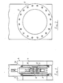
- the gate valve shown comprises a body 1, provided with counterposed coaxial flanges 2. Within the body 1 slides a shutter body 3 movable transversely of the axis of the passage 4 through the valve body 1. The movement of the valve shutter body 3 is effected by a control mechanism (not shown) acting on a connector 9 which will be described in more detail below.
- the valve shutter body 3 carries two coaxial shutter plates 5 mo vable towards and away from one another, and which during transverse translation of the said shutter body 3, and when the valve is open, are held in their positions of closest approach by a biasing spring 6.
- the separation of the said shutter plates 5 is con trolled by means of a drum 7 which can turn about an axis which coincides with that of the plates 5 themselves.
- This drum is mounted between the plates and is turned by a cranked link 8 which mechanically is equivalent to a crank and connecting rod system capable of transforming a small rectilinear movement into a small angular rotation.
- valve shutter position control member (not illustrated) is also connected to one end of the cranked link 8 of the mechanical body for causing separation of the said valve shutter plates 5.
- These latter are mounted on a ball joint 10 secured by a roller cage 11 and carry, at the perimeter of their outwardly directed faces, respective toroidal sealing rings 12 which, when the plates 5 are forced apart in the closed position of the valve shutter body, press on the facing valve seats to achieve a secure fluid-tight seal.
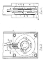
- the drum 7 is provided with at least two pairs of balls 13 captive in seats formed in its lateral faces: these balls are engageable with co-operating inclined planes 14 fixed in corresponding positions on the said shutter plates 5 of the valve shutter body 3.
- these balls 13 In the open position of the valve shutter the balls 13 contact only that part of associated inclined plane surface furthest from the median plane of the shutter body 3.
- the drum 7 is turned, however, (in a manner which will be described below) the balls 13 move along the corresponding inclined planes and since the balls 13 are captive and cannot move inwardly, the inclined planes 14, and therefore the valve shutter plates 5 are forced to move apart against the action of the spring 6.
- valve shutter plates 5 can take place only when the valve body 3 of which they form part is located in the valve closed position obstructing the passage passing through the valve body.
- the position control member continues to move for a further short distance, which is possible because the connector 9 is carried at the end of a plunger rod 17, which is guided in a housing 18, in which it is retained by a collar 19 and biased by a spring 15 which is thus compressed by this further movement off the connector 9.
- This movement of the plunger rod 17 is transmitted, via the cranked link 8, to the drum 7 causing it to turn through a small angle to displace the balls 13 along the corresponding inclined planes 14.
- valve plates 5 are mounted on a ball joint they can position themselves automatically, so as to be perfectly co-planar with the associated valve seats, thus ensuring a perfect bi-lateral seal.
- valve body upon opening the valve, the biasing springs 6 and 15 which are compressed upon closure of the valve, release stored energy, the valve body thus remains in the closed position until the two valve shutter plates 5 have been dawn together thereby disengaging the associated sealing rings 12 from the associated valve seats 16 before the valve-opening displacement of the valve shutter body 3 commences.
Landscapes
- Engineering & Computer Science (AREA)
- General Engineering & Computer Science (AREA)
- Mechanical Engineering (AREA)
- Sliding Valves (AREA)
Applications Claiming Priority (2)
| Application Number | Priority Date | Filing Date | Title |
|---|---|---|---|
| IT20113/86A IT1190310B (it) | 1986-04-17 | 1986-04-17 | Valvola a saracinesca,per alto vuoto,atta a garantire una perfetta tenuta,rispetto ai due tronchi di tubo,posti a monte ed a valle della stessa |
| IT2011386 | 1986-04-17 |
Publications (2)
| Publication Number | Publication Date |
|---|---|
| EP0241629A2 true EP0241629A2 (de) | 1987-10-21 |
| EP0241629A3 EP0241629A3 (de) | 1988-03-30 |
Family
ID=11163900
Family Applications (1)
| Application Number | Title | Priority Date | Filing Date |
|---|---|---|---|
| EP86830283A Withdrawn EP0241629A3 (de) | 1986-04-17 | 1986-10-03 | Schieber mit Dichtung |
Country Status (2)
| Country | Link |
|---|---|
| EP (1) | EP0241629A3 (de) |
| IT (1) | IT1190310B (de) |
Cited By (6)
| Publication number | Priority date | Publication date | Assignee | Title |
|---|---|---|---|---|
| RU2211977C2 (ru) * | 2001-09-26 | 2003-09-10 | Экрам Абульфас оглы Исмиев | Задвижка |
| CN101629636B (zh) * | 2009-08-18 | 2012-09-26 | 吴晓磊 | 一种阀门 |
| CN107013696A (zh) * | 2017-06-16 | 2017-08-04 | 洪德隆 | 无磨损撑开式球面闸阀 |
| CN110195784A (zh) * | 2019-06-28 | 2019-09-03 | 郑州金诚信筛网设备有限公司 | 一种全自动气密性插板阀 |
| CN114526348A (zh) * | 2020-11-23 | 2022-05-24 | 中核苏阀科技实业股份有限公司 | 一种楔式闸阀密封副的制造方法及其楔式闸阀密封副 |
| CN116412260A (zh) * | 2022-01-05 | 2023-07-11 | 新莱应材科技有限公司 | 利用弹力启闭的闸阀 |
Family Cites Families (8)
| Publication number | Priority date | Publication date | Assignee | Title |
|---|---|---|---|---|
| US1636297A (en) * | 1920-08-13 | 1927-07-19 | Fischbach Richard | Stop valve |
| FR698228A (fr) * | 1930-06-30 | 1931-01-28 | Vanne | |
| US1990762A (en) * | 1933-01-16 | 1935-02-12 | Leon J Vetrano | Valve mechanism |
| US2863629A (en) * | 1956-08-02 | 1958-12-09 | Hydril Co | Valve |
| FR1179088A (fr) * | 1957-07-18 | 1959-05-20 | Nantaise De Fonderies Reunies | Perfectionnement aux vannes à sièges parallèles |
| US3575377A (en) * | 1969-02-20 | 1971-04-20 | Willamette Iron And Steel Co | Closure seal for gate valve and method |
| FR2216492A1 (de) * | 1973-02-02 | 1974-08-30 | Bouchon Gaston | |
| US4291861A (en) * | 1980-08-04 | 1981-09-29 | Thermionics Laboratory, Inc. | Gate valve with slideable closure expandable upon oscillation |
-
1986
- 1986-04-17 IT IT20113/86A patent/IT1190310B/it active
- 1986-10-03 EP EP86830283A patent/EP0241629A3/de not_active Withdrawn
Cited By (6)
| Publication number | Priority date | Publication date | Assignee | Title |
|---|---|---|---|---|
| RU2211977C2 (ru) * | 2001-09-26 | 2003-09-10 | Экрам Абульфас оглы Исмиев | Задвижка |
| CN101629636B (zh) * | 2009-08-18 | 2012-09-26 | 吴晓磊 | 一种阀门 |
| CN107013696A (zh) * | 2017-06-16 | 2017-08-04 | 洪德隆 | 无磨损撑开式球面闸阀 |
| CN110195784A (zh) * | 2019-06-28 | 2019-09-03 | 郑州金诚信筛网设备有限公司 | 一种全自动气密性插板阀 |
| CN114526348A (zh) * | 2020-11-23 | 2022-05-24 | 中核苏阀科技实业股份有限公司 | 一种楔式闸阀密封副的制造方法及其楔式闸阀密封副 |
| CN116412260A (zh) * | 2022-01-05 | 2023-07-11 | 新莱应材科技有限公司 | 利用弹力启闭的闸阀 |
Also Published As
| Publication number | Publication date |
|---|---|
| IT1190310B (it) | 1988-02-16 |
| IT8620113A1 (it) | 1987-10-17 |
| IT8620113A0 (it) | 1986-04-17 |
| EP0241629A3 (de) | 1988-03-30 |
Similar Documents
| Publication | Publication Date | Title |
|---|---|---|
| EP0020688B1 (de) | Einstellbarer absperrschieber zur regulierung einer materialströmung | |
| US9739380B2 (en) | Butterfly pressure control valve | |
| US8424843B2 (en) | Shuttle valve having two drives | |
| US4103712A (en) | Positive isolation disconnect | |
| GB2116680A (en) | Slide valve | |
| US4546953A (en) | Ball valve | |
| US4231549A (en) | Valve stem and valve disc connection for a diaphragm valve | |
| US3185435A (en) | Valve construction | |
| US4285493A (en) | Valve operator | |
| EP0241629A2 (de) | Schieber mit Dichtung | |
| EP0565786A1 (de) | Vakuumschieber | |
| US4206900A (en) | Valve operator | |
| US2718372A (en) | Gate valve | |
| DE68903791T2 (de) | Ventil-uebersteuerungsmechanismus. | |
| US4356760A (en) | Ram locking device | |
| US5029809A (en) | Valve-control device and valve having such a control device | |
| US4195813A (en) | Valve | |
| US4932631A (en) | Apparatus to transmit drive force between two components | |
| DE2523202B2 (de) | Leckagefrei schaltendes doppeldichtendes Ventil mit Leckkontrollöffnung | |
| US2763290A (en) | Preselectable valve actuator | |
| DE3205155A1 (de) | "durch ein gasfoermiges stroemungsmedium betaetigbare servoeinrichtung zum schalten von aggregaten" | |
| EP0296330A2 (de) | Dreiwegverteilerventil | |
| DE2208453C3 (de) | Antriebseinrichtung zur Betätigung eines Absperrventils | |
| US4682621A (en) | Modulator valve | |
| GB929192A (en) | Improvements in or relating to valves for controlling the flow of steam, air, gases,or other fluids |
Legal Events
| Date | Code | Title | Description |
|---|---|---|---|
| PUAI | Public reference made under article 153(3) epc to a published international application that has entered the european phase |
Free format text: ORIGINAL CODE: 0009012 |
|
| AK | Designated contracting states |
Kind code of ref document: A2 Designated state(s): AT BE CH DE FR GB LI NL SE |
|
| PUAL | Search report despatched |
Free format text: ORIGINAL CODE: 0009013 |
|
| AK | Designated contracting states |
Kind code of ref document: A3 Designated state(s): AT BE CH DE FR GB LI NL SE |
|
| STAA | Information on the status of an ep patent application or granted ep patent |
Free format text: STATUS: THE APPLICATION IS DEEMED TO BE WITHDRAWN |
|
| 18D | Application deemed to be withdrawn |
Effective date: 19881003 |
|
| RIN1 | Information on inventor provided before grant (corrected) |
Inventor name: CHIUPPI, ROLANDONOVATEC S.R.L. |