EP0241440A2 - System zur Überwachung des elektrochemischen Schutzes von versenkbaren metallischen Strukturen - Google Patents
System zur Überwachung des elektrochemischen Schutzes von versenkbaren metallischen Strukturen Download PDFInfo
- Publication number
- EP0241440A2 EP0241440A2 EP87850053A EP87850053A EP0241440A2 EP 0241440 A2 EP0241440 A2 EP 0241440A2 EP 87850053 A EP87850053 A EP 87850053A EP 87850053 A EP87850053 A EP 87850053A EP 0241440 A2 EP0241440 A2 EP 0241440A2
- Authority
- EP
- European Patent Office
- Prior art keywords
- steel structure
- conductor
- detected
- transducer
- values
- Prior art date
- Legal status (The legal status is an assumption and is not a legal conclusion. Google has not performed a legal analysis and makes no representation as to the accuracy of the status listed.)
- Granted
Links
- 239000002184 metal Substances 0.000 title claims abstract description 6
- 229910052751 metal Inorganic materials 0.000 title claims abstract description 6
- 239000004020 conductor Substances 0.000 claims abstract description 29
- 229910000831 Steel Inorganic materials 0.000 claims abstract description 23
- 239000010959 steel Substances 0.000 claims abstract description 23
- 238000012544 monitoring process Methods 0.000 claims abstract description 13
- 238000000034 method Methods 0.000 claims abstract description 9
- XLYOFNOQVPJJNP-UHFFFAOYSA-N water Substances O XLYOFNOQVPJJNP-UHFFFAOYSA-N 0.000 claims abstract description 7
- 230000005540 biological transmission Effects 0.000 claims description 4
- 238000007689 inspection Methods 0.000 description 5
- 230000007797 corrosion Effects 0.000 description 4
- 238000005260 corrosion Methods 0.000 description 4
- 239000010410 layer Substances 0.000 description 3
- 239000010426 asphalt Substances 0.000 description 2
- 230000005684 electric field Effects 0.000 description 2
- OKTJSMMVPCPJKN-UHFFFAOYSA-N Carbon Chemical compound [C] OKTJSMMVPCPJKN-UHFFFAOYSA-N 0.000 description 1
- HCHKCACWOHOZIP-UHFFFAOYSA-N Zinc Chemical compound [Zn] HCHKCACWOHOZIP-UHFFFAOYSA-N 0.000 description 1
- 230000007175 bidirectional communication Effects 0.000 description 1
- 238000004210 cathodic protection Methods 0.000 description 1
- 238000010276 construction Methods 0.000 description 1
- 230000007850 degeneration Effects 0.000 description 1
- 238000001514 detection method Methods 0.000 description 1
- 239000012530 fluid Substances 0.000 description 1
- 239000010439 graphite Substances 0.000 description 1
- 229910002804 graphite Inorganic materials 0.000 description 1
- 238000009434 installation Methods 0.000 description 1
- 239000007788 liquid Substances 0.000 description 1
- 238000004519 manufacturing process Methods 0.000 description 1
- -1 platina Substances 0.000 description 1
- 239000011241 protective layer Substances 0.000 description 1
- 230000001360 synchronised effect Effects 0.000 description 1
- 238000011179 visual inspection Methods 0.000 description 1
- 229910052725 zinc Inorganic materials 0.000 description 1
- 239000011701 zinc Substances 0.000 description 1
Images
Classifications
-
- C—CHEMISTRY; METALLURGY
- C23—COATING METALLIC MATERIAL; COATING MATERIAL WITH METALLIC MATERIAL; CHEMICAL SURFACE TREATMENT; DIFFUSION TREATMENT OF METALLIC MATERIAL; COATING BY VACUUM EVAPORATION, BY SPUTTERING, BY ION IMPLANTATION OR BY CHEMICAL VAPOUR DEPOSITION, IN GENERAL; INHIBITING CORROSION OF METALLIC MATERIAL OR INCRUSTATION IN GENERAL
- C23F—NON-MECHANICAL REMOVAL OF METALLIC MATERIAL FROM SURFACE; INHIBITING CORROSION OF METALLIC MATERIAL OR INCRUSTATION IN GENERAL; MULTI-STEP PROCESSES FOR SURFACE TREATMENT OF METALLIC MATERIAL INVOLVING AT LEAST ONE PROCESS PROVIDED FOR IN CLASS C23 AND AT LEAST ONE PROCESS COVERED BY SUBCLASS C21D OR C22F OR CLASS C25
- C23F13/00—Inhibiting corrosion of metals by anodic or cathodic protection
- C23F13/02—Inhibiting corrosion of metals by anodic or cathodic protection cathodic; Selection of conditions, parameters or procedures for cathodic protection, e.g. of electrical conditions
- C23F13/04—Controlling or regulating desired parameters
-
- G—PHYSICS
- G01—MEASURING; TESTING
- G01N—INVESTIGATING OR ANALYSING MATERIALS BY DETERMINING THEIR CHEMICAL OR PHYSICAL PROPERTIES
- G01N17/00—Investigating resistance of materials to the weather, to corrosion, or to light
- G01N17/02—Electrochemical measuring systems for weathering, corrosion or corrosion-protection measurement
Definitions
- the invention relates to a method and device for automatic surveillance of electrochemical protection on submersible metal structures, wherein the difference in electric potential between the steel structure and at least one electrode in contact with the ambient water, is detected with a supply of electric alternating current.
- a major problem here is corrosion and anodic or cathodic protection is used as corrosion protection on oil and gas pipes, onshore or offshore and also on stressed steel structures, offshore. Either this corrosion protection is produced by an electric current or by sacrificial anodes, it is vital that the protection does not degenerate as time pass. Causes for degeneration may be damages to the mechanically applied surface protection, faults in sacrificial anode systems etc.
- the object of the present invention is to provide such a monitoring system, which is adapted to the special conditions existing, e.g. when laying pipe lines offshore.
- the method according to the invention is characterized in that the current is supplied via the steel structure and as parallell, insulated conductor, that said difference in electric potential is detected by means of a transducer at each of said electrodes, which transforms said value from its electrode to a first pulse coded signal component to which is added a second pulse coded address signal, which is unique for each transducer and is used to identify the position of said value along the steel structure, and that the detected values are transmitted to a central monitoring unit recording said values, via said steel structure and said conductor, as a pulse coded signal, superposed upon the supply current, which acts as a system clock.
- the transducers are selectively activated by means of an address signal from the central monitoring unit for individual report of present potential value.
- the transducers are activated when the potential value surpasses a present limit value, for report to the central unit.
- An apparatus is characterized in that a number of electrodes are placed at intervals along the surface of the steel structure, so that they are in contact with the water and are interconnected to each other via a transducer, which communicates with a central monitoring unit via the steel structure and a parallell, insulated conductor for transmission of supply current to the transducers and detected values to said central unit, said values having their source from the difference in electric potential between the respective electrode and said surface.
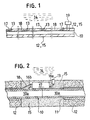
- FIGS. 1 and 2 indicate the steel pipe which surface protection will be detected.
- the pipe is made of several welded sections 10a. Over a large part of their length, they are covered by a protective layer 11 of asphalt and over said layer an outer heavy layer 12 of concrete for negative buoyancy.
- An electrode 13 from other metal than steel, e.g. platina, graphite or zinc is placed in contact with the ambient water 14. A preferable location for the electrode is in the gap existing between the concrete of two adjacent sections before this gap has been filled by a mass 15.
- An electric field force is created between the steel pipe 10 and the electrode 13, which can be detected by means of a highohmic detector device.
- the measured field force is directly proportional to the electrochemical protection of the pipe.
- FIG. 2 is shown how the electrode 13 is connected via a short conductor 16a to an electronic transducer 17, which also is connected to the pipe 10 via a short conductor 16b.
- the transducer transforms the electric field force into a pulse coded modulated digital signal, wherein the pulse code has a mathematic relationship with said field force.
- the transducer 17 is also connected in series with a conductor 18 which runs along the entire length of the pipe. By this single conductor 18, having the pipe 10 as the second terminal, the power is supplied to the transducer 17 and the above described pulse code is transmitted to a central monitoring unit 19 (see FIG. 1) at one end of the conductor 18.
- the transducer 17 is designed to receive signals from the conductor 18 and act to these signals by sending its pulse coded signal. The operation of the complete system having any number of transducers and electrodes will now be described in the following.
- one conductor section will be moulded in along one pipe section, preferably in the asphalt layer.
- the conductor sections are also welded together. Since there is only one conductor to splice, the time required for splicing this conductor and installing the electrodes and transducers will be minimized.
- the energy transmitted by the long conductor 18 mainly is composed of alternating current signals.
- Direct current would imply a risk for galvanic corrosion on the conductor if it cannot be guaranteed that the conductor will be completely free from moisture. In the type of environment that the invention mainly will be used in, such freedom of moisture can hardly be maintained.
- FIG. 1 shows an arrangement for bidirectional communication and simultaneous supply of energy along the longitudinal conductor 18 having the steep pipe 10 as a second terminal.
- One end of the conductor 18 is connected to the central monitoring unit 19, which emits an alternating current.
- the unit 19 wants to communicate with any of the transducers connected to the conductor 18, the voltage wave of the alternating current is pulse modulated in such way that a certain address and a message is formed.
- FIG. 1 also show how a number of transducers 17 are connected to the conductor 18.
- Each transducer 17 has its own pulse code combination which serves both as identification sign when a message is transmitted and an address when messages are received. All message signals, either transmitted or received, are synchronized by means of said alternating current signal, which acts as a system clock.
- the transducers normally are standing by; i.e. they are not sending any messages, only listening drawing a minimum of energy. They can be activated either by a question signal from the central 19 with a specific address to one of the transducers in the system; or they can activate themselves in case the limit value from the steel pipe 10 and the electrode 13 falls beyond a preset area of acceptable readings.
- a transducer When a transducer is activated in any of the above or other ways, it sends a message to the central 19 via the conductor 18. The message starts with the specific address code of the transducer 17 and continues with a report of the present status of the electric potential. This report may trigger an alarm in the central 19 and the message from the transducer 17 will be recorded.
- the device may be modified for use at an offshore steel construction, e.g. a fixed or floating platform for development of oil or gas. Therefore monitoring circuits may run along stressed struts or beams, and several electrodes may be connected to the same transducer, so that a medium value for the electric potential at a certain part of the structure may be detected.
- the control system according to the invention can be used for transmission of other information, e.g. pressure or temperature.
- the conductor may comprise several electric cords, running in parallel between two points for increased safety against a rupture.
Landscapes
- Chemical & Material Sciences (AREA)
- Life Sciences & Earth Sciences (AREA)
- General Health & Medical Sciences (AREA)
- General Physics & Mathematics (AREA)
- Environmental Sciences (AREA)
- Physics & Mathematics (AREA)
- Health & Medical Sciences (AREA)
- Ecology (AREA)
- Analytical Chemistry (AREA)
- Biochemistry (AREA)
- Biodiversity & Conservation Biology (AREA)
- Environmental & Geological Engineering (AREA)
- Immunology (AREA)
- Pathology (AREA)
- Engineering & Computer Science (AREA)
- Materials Engineering (AREA)
- Mechanical Engineering (AREA)
- Metallurgy (AREA)
- Organic Chemistry (AREA)
- Prevention Of Electric Corrosion (AREA)
- Preventing Corrosion Or Incrustation Of Metals (AREA)
- Pipeline Systems (AREA)
Applications Claiming Priority (2)
| Application Number | Priority Date | Filing Date | Title |
|---|---|---|---|
| SE8600741 | 1986-02-19 | ||
| SE8600741A SE456191B (sv) | 1986-02-19 | 1986-02-19 | Forfarande och anordning for automatisk overvakning av elektrokemiskt korrosionsskydd vid en i vatten befintlig stalkonstruktion |
Publications (3)
| Publication Number | Publication Date |
|---|---|
| EP0241440A2 true EP0241440A2 (de) | 1987-10-14 |
| EP0241440A3 EP0241440A3 (en) | 1989-07-19 |
| EP0241440B1 EP0241440B1 (de) | 1993-01-13 |
Family
ID=20363523
Family Applications (1)
| Application Number | Title | Priority Date | Filing Date |
|---|---|---|---|
| EP19870850053 Expired - Lifetime EP0241440B1 (de) | 1986-02-19 | 1987-02-13 | System zur Überwachung des elektrochemischen Schutzes von versenkbaren metallischen Strukturen |
Country Status (5)
| Country | Link |
|---|---|
| EP (1) | EP0241440B1 (de) |
| DE (1) | DE3783500T2 (de) |
| DK (1) | DK78387A (de) |
| NO (1) | NO870640L (de) |
| SE (1) | SE456191B (de) |
Cited By (7)
| Publication number | Priority date | Publication date | Assignee | Title |
|---|---|---|---|---|
| AT396175B (de) * | 1987-12-11 | 1993-06-25 | Vaillant Gmbh | In die wandung eines warmwasserspeichers ragende schutzanode |
| WO2001004381A1 (en) * | 1999-07-13 | 2001-01-18 | Flight Refuelling Limited | Anode monitoring systems and methods |
| WO2001086256A1 (fr) * | 2000-05-11 | 2001-11-15 | Institut Francais Du Petrole | Methode et dispositif de detection de la corrosion induite microbiologiquement |
| WO2002053804A1 (en) * | 2001-01-03 | 2002-07-11 | Flight Refuelling Limited | Subsea pipeline power transmission |
| US6788075B2 (en) | 1999-07-13 | 2004-09-07 | Flight Refuelling Limited | Anode monitoring |
| US6809506B2 (en) * | 2001-03-26 | 2004-10-26 | The United States Of America As Represented By The Secretary Of The Navy | Corrosion sensor loudspeaker for active noise control |
| WO2014088656A1 (en) * | 2012-12-04 | 2014-06-12 | Itron, Inc. | Pipeline communications |
Family Cites Families (3)
| Publication number | Priority date | Publication date | Assignee | Title |
|---|---|---|---|---|
| FR2359413A1 (fr) * | 1976-07-21 | 1978-02-17 | Coprelec | Procede d'evaluation du degre de protection cathodique d'une piece metallique enterree, notamment une canalisation, et dispositifs pour la mise en oeuvre de ce procede |
| FR2423776A1 (fr) * | 1978-04-19 | 1979-11-16 | Exper Rech Etu Batiment Centre | Procede et appareillage de detection de fissures dans une paroi de beton immergee |
| JPS56123383A (en) * | 1980-02-29 | 1981-09-28 | Nec Corp | Information transmission system for controlling corrosion prevention |
-
1986
- 1986-02-19 SE SE8600741A patent/SE456191B/sv not_active IP Right Cessation
-
1987
- 1987-02-13 DE DE19873783500 patent/DE3783500T2/de not_active Expired - Fee Related
- 1987-02-13 EP EP19870850053 patent/EP0241440B1/de not_active Expired - Lifetime
- 1987-02-17 DK DK78387A patent/DK78387A/da not_active Application Discontinuation
- 1987-02-18 NO NO870640A patent/NO870640L/no unknown
Cited By (11)
| Publication number | Priority date | Publication date | Assignee | Title |
|---|---|---|---|---|
| AT396175B (de) * | 1987-12-11 | 1993-06-25 | Vaillant Gmbh | In die wandung eines warmwasserspeichers ragende schutzanode |
| WO2001004381A1 (en) * | 1999-07-13 | 2001-01-18 | Flight Refuelling Limited | Anode monitoring systems and methods |
| AU765041B2 (en) * | 1999-07-13 | 2003-09-04 | Flight Refuelling Limited | Anode monitoring systems and methods |
| US6788075B2 (en) | 1999-07-13 | 2004-09-07 | Flight Refuelling Limited | Anode monitoring |
| US6835291B2 (en) | 1999-07-13 | 2004-12-28 | Expro North Sea Limited | Anode monitoring and subsea pipeline power transmission |
| WO2001086256A1 (fr) * | 2000-05-11 | 2001-11-15 | Institut Francais Du Petrole | Methode et dispositif de detection de la corrosion induite microbiologiquement |
| FR2808881A1 (fr) * | 2000-05-11 | 2001-11-16 | Inst Francais Du Petrole | Methode et dispositif de detection de la corrosion induite microbiologiquement |
| WO2002053804A1 (en) * | 2001-01-03 | 2002-07-11 | Flight Refuelling Limited | Subsea pipeline power transmission |
| US6809506B2 (en) * | 2001-03-26 | 2004-10-26 | The United States Of America As Represented By The Secretary Of The Navy | Corrosion sensor loudspeaker for active noise control |
| WO2014088656A1 (en) * | 2012-12-04 | 2014-06-12 | Itron, Inc. | Pipeline communications |
| US9005423B2 (en) | 2012-12-04 | 2015-04-14 | Itron, Inc. | Pipeline communications |
Also Published As
| Publication number | Publication date |
|---|---|
| NO870640D0 (no) | 1987-02-18 |
| NO870640L (no) | 1987-08-20 |
| DK78387A (da) | 1987-08-20 |
| SE8600741D0 (sv) | 1986-02-19 |
| SE456191B (sv) | 1988-09-12 |
| EP0241440B1 (de) | 1993-01-13 |
| DE3783500D1 (de) | 1993-02-25 |
| DK78387D0 (da) | 1987-02-17 |
| SE8600741L (sv) | 1987-08-20 |
| DE3783500T2 (de) | 1993-08-05 |
| EP0241440A3 (en) | 1989-07-19 |
Similar Documents
| Publication | Publication Date | Title |
|---|---|---|
| US4826577A (en) | Control system for electrochemical protection on submersible metal structures | |
| US4503710A (en) | Crack detection by electrical resistance | |
| US5378991A (en) | Detecting degradation of non-conductive inert wall layers in fluid containers | |
| KR101098528B1 (ko) | 관로 감시 시스템 및 방법 | |
| EP1739423A2 (de) | Überwachungsvorrichtung | |
| CA1083528A (en) | Method and apparatus for monitoring a cathodically protected corrodible hollow member | |
| EP0495259B1 (de) | Vorrichtung und Verfahren zum kontinuierlichen Überwachen von zufällig auftretenden Beschädigungen an Schutzverkleidungen von unterirdischen oder unter-Wasser angeordneten metallischen Konstruktionen oder Rohrleitungen | |
| US4090170A (en) | Process and apparatus for investigating the activity of a cathodic protection unit | |
| US12601452B2 (en) | Pipeline integrity monitoring system (PIMS) for oil, gas and other pipelines | |
| EP0241440B1 (de) | System zur Überwachung des elektrochemischen Schutzes von versenkbaren metallischen Strukturen | |
| US4644285A (en) | Method and apparatus for direct measurement of current density | |
| EP2425228B1 (de) | Vorrichtung zur anzeige kritischer korrosionen einer metallischen struktur | |
| US4489277A (en) | Cathodic protection monitoring system | |
| WO2011051570A1 (en) | Device and method for leak indication | |
| Fitzgerald III | Corrosion as a Primary Cause of Cast‐Iron Main Breaks | |
| US4639677A (en) | Cathodic protection monitoring system | |
| KR20080109455A (ko) | 파손 감지 및 관로 위치 파악이 용이한 감지관 | |
| WO2017039017A1 (ja) | ケーブル被覆損傷位置検出方法、およびケーブル被覆損傷位置検出装置 | |
| US4143540A (en) | Method of preventing corrosion of joints of steel structures submerged in corrosive media | |
| KR102737047B1 (ko) | 센서가 장착된 플랜지용 개스킷형 희생양극 및 그를 이용한 누설 탐지 시스템 | |
| GB2124382A (en) | Determining the level of protection provided by a submarine cathodic protection system | |
| GB2521864A (en) | Pipe integrity survey | |
| Leeds et al. | Cathodic protection | |
| Thodi et al. | Real-time Arctic pipeline integrity and leak monitoring | |
| KR102701571B1 (ko) | 피복배관의 내외피 결함 탐지시스템 |
Legal Events
| Date | Code | Title | Description |
|---|---|---|---|
| PUAI | Public reference made under article 153(3) epc to a published international application that has entered the european phase |
Free format text: ORIGINAL CODE: 0009012 |
|
| AK | Designated contracting states |
Kind code of ref document: A2 Designated state(s): DE FR GB IT NL |
|
| PUAL | Search report despatched |
Free format text: ORIGINAL CODE: 0009013 |
|
| AK | Designated contracting states |
Kind code of ref document: A3 Designated state(s): DE FR GB IT NL |
|
| 17P | Request for examination filed |
Effective date: 19891120 |
|
| 17Q | First examination report despatched |
Effective date: 19910620 |
|
| GRAA | (expected) grant |
Free format text: ORIGINAL CODE: 0009210 |
|
| RAP1 | Party data changed (applicant data changed or rights of an application transferred) |
Owner name: BAC BERGSOEE ANTI CORROSION AB |
|
| AK | Designated contracting states |
Kind code of ref document: B1 Designated state(s): DE FR GB IT NL |
|
| PG25 | Lapsed in a contracting state [announced via postgrant information from national office to epo] |
Ref country code: IT Free format text: LAPSE BECAUSE OF FAILURE TO SUBMIT A TRANSLATION OF THE DESCRIPTION OR TO PAY THE FEE WITHIN THE PRESCRIBED TIME-LIMIT;WARNING: LAPSES OF ITALIAN PATENTS WITH EFFECTIVE DATE BEFORE 2007 MAY HAVE OCCURRED AT ANY TIME BEFORE 2007. THE CORRECT EFFECTIVE DATE MAY BE DIFFERENT FROM THE ONE RECORDED. Effective date: 19930113 |
|
| REF | Corresponds to: |
Ref document number: 3783500 Country of ref document: DE Date of ref document: 19930225 |
|
| PGFP | Annual fee paid to national office [announced via postgrant information from national office to epo] |
Ref country code: NL Payment date: 19930228 Year of fee payment: 7 |
|
| PGFP | Annual fee paid to national office [announced via postgrant information from national office to epo] |
Ref country code: GB Payment date: 19930316 Year of fee payment: 7 |
|
| RIN2 | Information on inventor provided after grant (corrected) |
Free format text: LANGE, GOESTA |
|
| K2C1 | Correction of patent specification (title page) published |
Effective date: 19930113 |
|
| PGFP | Annual fee paid to national office [announced via postgrant information from national office to epo] |
Ref country code: DE Payment date: 19930415 Year of fee payment: 7 |
|
| PGFP | Annual fee paid to national office [announced via postgrant information from national office to epo] |
Ref country code: FR Payment date: 19930423 Year of fee payment: 7 |
|
| ET | Fr: translation filed | ||
| PLBE | No opposition filed within time limit |
Free format text: ORIGINAL CODE: 0009261 |
|
| STAA | Information on the status of an ep patent application or granted ep patent |
Free format text: STATUS: NO OPPOSITION FILED WITHIN TIME LIMIT |
|
| 26N | No opposition filed | ||
| PG25 | Lapsed in a contracting state [announced via postgrant information from national office to epo] |
Ref country code: GB Effective date: 19940213 |
|
| PG25 | Lapsed in a contracting state [announced via postgrant information from national office to epo] |
Ref country code: NL Effective date: 19940901 |
|
| GBPC | Gb: european patent ceased through non-payment of renewal fee |
Effective date: 19940213 |
|
| NLV4 | Nl: lapsed or anulled due to non-payment of the annual fee | ||
| PG25 | Lapsed in a contracting state [announced via postgrant information from national office to epo] |
Ref country code: FR Effective date: 19941031 |
|
| PG25 | Lapsed in a contracting state [announced via postgrant information from national office to epo] |
Ref country code: DE Effective date: 19941101 |
|
| REG | Reference to a national code |
Ref country code: FR Ref legal event code: ST |