EP0241437B1 - Distributeur pneumatique duplex pour système de freinage de véhicules automobiles - Google Patents
Distributeur pneumatique duplex pour système de freinage de véhicules automobiles Download PDFInfo
- Publication number
- EP0241437B1 EP0241437B1 EP87830121A EP87830121A EP0241437B1 EP 0241437 B1 EP0241437 B1 EP 0241437B1 EP 87830121 A EP87830121 A EP 87830121A EP 87830121 A EP87830121 A EP 87830121A EP 0241437 B1 EP0241437 B1 EP 0241437B1
- Authority
- EP
- European Patent Office
- Prior art keywords
- piston
- extension
- reaction
- valves
- reaction member
- Prior art date
- Legal status (The legal status is an assumption and is not a legal conclusion. Google has not performed a legal analysis and makes no representation as to the accuracy of the status listed.)
- Expired
Links
- 230000006835 compression Effects 0.000 claims abstract description 5
- 238000007906 compression Methods 0.000 claims abstract description 5
- 230000000644 propagated effect Effects 0.000 description 1
Images


Classifications
-
- B—PERFORMING OPERATIONS; TRANSPORTING
- B60—VEHICLES IN GENERAL
- B60T—VEHICLE BRAKE CONTROL SYSTEMS OR PARTS THEREOF; BRAKE CONTROL SYSTEMS OR PARTS THEREOF, IN GENERAL; ARRANGEMENT OF BRAKING ELEMENTS ON VEHICLES IN GENERAL; PORTABLE DEVICES FOR PREVENTING UNWANTED MOVEMENT OF VEHICLES; VEHICLE MODIFICATIONS TO FACILITATE COOLING OF BRAKES
- B60T15/00—Construction arrangement, or operation of valves incorporated in power brake systems and not covered by groups B60T11/00 or B60T13/00
- B60T15/02—Application and release valves
- B60T15/04—Driver's valves
- B60T15/043—Driver's valves controlling service pressure brakes
- B60T15/045—Driver's valves controlling service pressure brakes in multiple circuit systems, e.g. dual circuit systems
- B60T15/046—Driver's valves controlling service pressure brakes in multiple circuit systems, e.g. dual circuit systems with valves mounted in tandem
Definitions
- the present invention relates to a pneumatic distributor of the duplex type for motor vehicle braking systems.
- the invention provides a pneumatic distributor of the type comprising a body with first and second inlet connectors for connection to respective pressure sources, and first and second outlet connectors for connection to two separate brake circuits; first and second valves being formed coaxially in the body and arranged to put the first inlet connector into communication with the first outlet connector and the second inlet connector into communication with the second outlet connector respectively, the valves having a common control device including:
- the second resilient means comprise a helical spring which reacts at one end against a reaction surface of the body and at the other end against the extension of the first piston.
- This extension can return the second piston to the rest position, under the action of the helical spring,. when the brake is released.
- the helical spring between the body and the extension of the first piston is compressed as a result of the operation of the brake pedal and it contributes to the creation of a reaction to the foot which the driver must overcome to apply the brake.
- the object of the present invention is to provide a pneumatic distributor of the aforesaid type in which the second resilient means cooperating with the extension of the first piston do not provide any contribution to the reaction to the driver's foot during the initial phase of operation of the brake pedal until the condition of imminent opening of the valves of the distributor is reached.
- the second resilient means in the distributor of the invention do not load the brake pedal during the initial travel of the control pistons but contribute to the reaction to the driver's foot only when the opening of the valves is imminent, in practice providing a useful signal to the driver of the imminence of the application of the braking action.
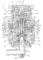
- a duplex-type pneumatic distributor of the invention is generally indicated 1.
- This distributor comprises a body 2 formed in two parts 2a, 2b sealed and clamped together by screws 3.
- the body 2 has an upper aperture 4 in which a cup-shaped piston 5 is sealingly movable.
- a drive cap 6 is movable in the piston and can be operated as a result of the operation of the brake pedal in known manner, not illustrated. Between the drive cap 6 and the piston 5 are springs 7, 8 and 9.
- Two inlet connectors 10 and 11 and corresponding outlet connectors 12 and 13 are provided in the body 2.
- the connectors 10 and 11 are intended for connection to two pressure reservoirs, while the connectors 12 and 13 are intended for connection to two independent brake circuits of a motor vehicle, for example, the front brake circuit and the rear brake circuit.
- the body 2 also has a lower exhaust connector 14 bent at 90° and having a threaded opening 14a closed by a screw stopper 14b.
- valve In the body 2, between the inlet connector 10 and the outlet connector 12, there is a valve comprising a seat 15 and an annular obturator 16 movable along the axis of the control piston 5. At its upper end, the obturator 16 carries an annular washer 17 cooperating with the valve seat 15.
- a second valve is provided between the inlet connector 11 and the outlet connector 13 and includes a seat 19 and an annular obturator 20 movable along the axis of the control piston 5.
- This obturator carries a washer 21 cooperating with the valve seat 19.
- a helical spring 22 urges the obturator 20 against the valve seat 19.
- annular piston 23 having a central tubular portion 23a sealingly slidable in the obturator 16.
- a spring 24 is interposed between an upper end shoulder of the obturator 16 and a shoulder of the portion 23a of the piston 23. The spring 24 urges the piston 23. downwardly.
- the tubular hub 23a of the piston 23 has an upper extension 23b of substantially frusto-conical form, with lateral slits 23c. This extension extends within the annular obturator 16 and a central aperture 25 is formed in its upper wall facing the control piston 5.
- a screw 26 has one end engaged in a central threaded aperture 5a in the control piston 5.
- the stem of this screw extends coaxially within the tubular hub 23a of the piston 23.
- Two tubular reaction members, indicated 27 and 28, are disposed for longitudinal movement on the screw 26 and between them is a helical spring 29 which biasses them away from each other.
- the upper reaction member 27 is in the form of a tubular sleeve and is movable through the aperture 25 in the top portion of the piston 23. In the rest condition (lack of braking) this reaction member bears at its upper end against the control piston 5.
- the reaction member has an external annular projection 27a which bears against the top wall of the portion 23b of the piston 23.
- the lower reaction member 28 has an internal shoulder 28a which bears against the head 26a of the screw 26. This reaction member also extends beyond the head of the screw 26, extending towards a frusto-conical tubular projection 30 of the body at the mouth of the exhaust connector 14.
- the helical spring 29 passes through the upper reaction member 27 to bias the piston 23 upwardly and oppose the action of the helical spring 24.
- a passage, indicated 31, puts the outlet connector 12 into communication with a chamber 32 above the piston 23.
- the control piston 5 has a central annular projection 5b which serves as a valve seat and cooperates with the washer 17 of the obturator 16 to disconnect the outlet connector 12 from the exhaust connector 14 during braking (as will be better described below).
- a helical spring 33 keeps the piston 5 in the position illustrated in Figure 2, in which the projection 5b is located at a certain distance from the annular obturator 16 in the rest condition of the distributor (lack of braking).
- the tubular hub 23a of the piston 23 has a lower projection 23d which serves as a valve seat and, as will be described below, cooperates with the washer 21 of the obturator 20 to disconnect the outlet 13 from the exhaust connector 14 during braking.
- the piston 23 In the rest condition of the distributor, as a result of the equilibrium between the springs 24 and 29, the piston 23 is kept in the position illustrated in Figure 2, in which the projection 23d is at a certain distance from the washer 21 of the obturator 20.
- the distributor described above operates in the following manner.
- the operation of the brake pedal causes, in known manner, the lowering of the drive cap 6 which causes the lowering of the control piston 5 and its extension represented by the screw 26 by means of the springs 7 and 8.
- the reaction members 27 and 28 move together with the screw 26 and the spring 29 is not stressed.
- the spring 24 can extend to push the control piston 23 downwardly.
- the edge 5b of the control piston 5 comes into contact with the washer 17 of the obturator 16 and breaks communication between the outlet connector 12 and the exhaust connector 14.
- the lower reaction member 28 abuts the frusto-conical member 30 fixed to the body 2 and is stopped relative to the screw 26 which is still able to descend.
- the further lowering of the control piston 5 thus causes compression of the spring 29.
- This spring therefore contributes to the reaction force on the driver's foot, which constitutes a signal to the driver of the imminent opening of the valves and hence of the imminent effective application of the braking force.
- the further descent of the control piston 5 causes the obturator 16 to move away from the valve seat 15 so that the pressure is propagated from the inlet connector 10 to the outlet connector 12.
- the chamber 32 is also pressurised through the passage 31 and the resulting force on the piston 23 causes the further downward movement of the latter, moving the obturator 20 away from the valve seat 19 and putting the inlet connector 11 into communication with the outlet connector 13.
- the spring 29 does not contribute at all to the reaction on the driver's foot. This spring is compressed and contributes to the reaction on the foot only immediately before the opening of the valves, providing a signal to the driver, as already stated.
Landscapes
- Engineering & Computer Science (AREA)
- Transportation (AREA)
- Mechanical Engineering (AREA)
- Braking Systems And Boosters (AREA)
- Valves And Accessory Devices For Braking Systems (AREA)
- Regulating Braking Force (AREA)
Claims (3)
Priority Applications (1)
| Application Number | Priority Date | Filing Date | Title |
|---|---|---|---|
| AT87830121T ATE43107T1 (de) | 1986-04-02 | 1987-03-31 | Zweikreissteuerventil fuer kraftfahrzeugbremsanlagen. |
Applications Claiming Priority (2)
| Application Number | Priority Date | Filing Date | Title |
|---|---|---|---|
| IT6726586 | 1986-04-02 | ||
| IT67265/86A IT1190559B (it) | 1986-04-02 | 1986-04-02 | Distributore pneumatico di tipo duplex per impianti di frenatura per autoveicoli |
Publications (2)
| Publication Number | Publication Date |
|---|---|
| EP0241437A1 EP0241437A1 (fr) | 1987-10-14 |
| EP0241437B1 true EP0241437B1 (fr) | 1989-05-17 |
Family
ID=11300975
Family Applications (1)
| Application Number | Title | Priority Date | Filing Date |
|---|---|---|---|
| EP87830121A Expired EP0241437B1 (fr) | 1986-04-02 | 1987-03-31 | Distributeur pneumatique duplex pour système de freinage de véhicules automobiles |
Country Status (6)
| Country | Link |
|---|---|
| US (1) | US4741579A (fr) |
| EP (1) | EP0241437B1 (fr) |
| AT (1) | ATE43107T1 (fr) |
| DE (1) | DE3760157D1 (fr) |
| ES (1) | ES2008876B3 (fr) |
| IT (1) | IT1190559B (fr) |
Families Citing this family (6)
| Publication number | Priority date | Publication date | Assignee | Title |
|---|---|---|---|---|
| IT208269Z2 (it) * | 1986-10-27 | 1988-04-29 | Magneti Marelli Spa | Distributore di tipo duplex per un impianto pneumatico di frenatura per autoveicolo provvisto di rallentatore ausiliario |
| DE3830105A1 (de) * | 1988-09-05 | 1990-03-15 | Knorr Bremse Ag | Bremsventil fuer druckluftbremsanlagen von fahrzeugen |
| CN102529939A (zh) * | 2012-02-16 | 2012-07-04 | 河南昌通科技有限公司 | 三级平衡活塞总成 |
| US9932025B2 (en) * | 2013-12-20 | 2018-04-03 | Wabco India Limited | Pneumatic control valve |
| WO2015092500A1 (fr) * | 2013-12-20 | 2015-06-25 | Wabco India Limited | Soupape de commande pneumatique |
| CN104192130B (zh) * | 2014-09-22 | 2016-10-05 | 昌通科技有限公司 | 北方奔驰带减速的二级、三级点刹制动总阀 |
Family Cites Families (6)
| Publication number | Priority date | Publication date | Assignee | Title |
|---|---|---|---|---|
| US3152844A (en) * | 1963-10-25 | 1964-10-13 | Wagner Electric Corp | Control valve |
| DE2736661C2 (de) * | 1977-08-13 | 1987-04-02 | Robert Bosch Gmbh, 7000 Stuttgart | Zweikreis-Steuerventil |
| DE2737628A1 (de) * | 1977-08-20 | 1979-02-22 | Bosch Gmbh Robert | Zweikreis-steuerventil |
| DE2817991A1 (de) * | 1978-04-25 | 1979-11-08 | Bosch Gmbh Robert | Zweikreis-steuerventil |
| GB8402295D0 (en) * | 1984-01-28 | 1984-02-29 | Bendix Ltd | Multi-circuit fluid pressure control valve |
| GB2158534B (en) * | 1984-05-05 | 1988-04-20 | Bendix Ltd | Venting compressed air brakes |
-
1986
- 1986-04-02 IT IT67265/86A patent/IT1190559B/it active
-
1987
- 1987-03-31 EP EP87830121A patent/EP0241437B1/fr not_active Expired
- 1987-03-31 DE DE8787830121T patent/DE3760157D1/de not_active Expired
- 1987-03-31 ES ES87830121T patent/ES2008876B3/es not_active Expired
- 1987-03-31 AT AT87830121T patent/ATE43107T1/de not_active IP Right Cessation
- 1987-04-02 US US07/033,377 patent/US4741579A/en not_active Expired - Fee Related
Also Published As
| Publication number | Publication date |
|---|---|
| US4741579A (en) | 1988-05-03 |
| ES2008876B3 (es) | 1989-08-16 |
| DE3760157D1 (en) | 1989-06-22 |
| IT8667265A0 (it) | 1986-04-02 |
| ATE43107T1 (de) | 1989-06-15 |
| EP0241437A1 (fr) | 1987-10-14 |
| IT1190559B (it) | 1988-02-16 |
Similar Documents
| Publication | Publication Date | Title |
|---|---|---|
| EP0241437B1 (fr) | Distributeur pneumatique duplex pour système de freinage de véhicules automobiles | |
| US3992065A (en) | Brake control valve device for fluid pressure operable dual brake systems for motor vehicles | |
| US3064670A (en) | Pressure reducing devices | |
| JPS5853620B2 (ja) | 車輛負荷感知装置 | |
| US4453779A (en) | Adjustable variable load control valve device | |
| US5791746A (en) | Valve arrangement for controlling the brake pressure in a vehicle hydraulic power-brake system | |
| US3650571A (en) | Fluid pressure braking systems | |
| US3425750A (en) | Bleed apparatus for bleeding the brakes of a hybrid hydraulic brake system | |
| US4318272A (en) | Brake force amplifier | |
| US4609230A (en) | Dual brake valves | |
| EP0241436B1 (fr) | Valve pneumatique pour systèmes de freinage | |
| US3941431A (en) | Inertia and load responsive device for limiting braking pressure | |
| US4008925A (en) | Valve devices for use in liquid pressure braking systems of vehicles | |
| US5213397A (en) | Freight brake control valve for railway cars | |
| JPS60222350A (ja) | 制動補正装置 | |
| GB1395823A (en) | Load sensitive device | |
| US4840433A (en) | Pressure control device, in particular for pressure-fluid-operable brake systems of automotive vehicles | |
| US4025125A (en) | Fluid pressure operable brake control valve apparatus | |
| US4331364A (en) | Hydraulic pressure control valve | |
| EP0252267A3 (fr) | Vanne-pilote pour servofrein à vide | |
| GB2027229A (en) | Fluid pressure regulators | |
| US5172957A (en) | Fluid pressure control apparatus | |
| EP0260805B1 (fr) | Vannes pilotes à pression fluide | |
| EP0027032B1 (fr) | Vannes à recouvrement automatique et joints à pression de fluide | |
| US4822110A (en) | Pneumatic valve, particularly a duplex-type distributor for a braking system, including a device for limiting the maximum distributable pressure |
Legal Events
| Date | Code | Title | Description |
|---|---|---|---|
| PUAI | Public reference made under article 153(3) epc to a published international application that has entered the european phase |
Free format text: ORIGINAL CODE: 0009012 |
|
| AK | Designated contracting states |
Kind code of ref document: A1 Designated state(s): AT BE CH DE ES FR GB GR IT LI LU NL SE |
|
| 17P | Request for examination filed |
Effective date: 19871214 |
|
| 17Q | First examination report despatched |
Effective date: 19880715 |
|
| GRAA | (expected) grant |
Free format text: ORIGINAL CODE: 0009210 |
|
| AK | Designated contracting states |
Kind code of ref document: B1 Designated state(s): AT BE CH DE ES FR GB GR IT LI LU NL SE |
|
| PG25 | Lapsed in a contracting state [announced via postgrant information from national office to epo] |
Ref country code: NL Effective date: 19890517 Ref country code: LI Effective date: 19890517 Ref country code: GR Free format text: LAPSE BECAUSE OF FAILURE TO SUBMIT A TRANSLATION OF THE DESCRIPTION OR TO PAY THE FEE WITHIN THE PRESCRIBED TIME-LIMIT Effective date: 19890517 Ref country code: CH Effective date: 19890517 Ref country code: BE Effective date: 19890517 Ref country code: AT Effective date: 19890517 |
|
| REF | Corresponds to: |
Ref document number: 43107 Country of ref document: AT Date of ref document: 19890615 Kind code of ref document: T |
|
| ITF | It: translation for a ep patent filed | ||
| REF | Corresponds to: |
Ref document number: 3760157 Country of ref document: DE Date of ref document: 19890622 |
|
| ET | Fr: translation filed | ||
| REG | Reference to a national code |
Ref country code: CH Ref legal event code: PL |
|
| NLV1 | Nl: lapsed or annulled due to failure to fulfill the requirements of art. 29p and 29m of the patents act | ||
| PLBE | No opposition filed within time limit |
Free format text: ORIGINAL CODE: 0009261 |
|
| STAA | Information on the status of an ep patent application or granted ep patent |
Free format text: STATUS: NO OPPOSITION FILED WITHIN TIME LIMIT |
|
| PG25 | Lapsed in a contracting state [announced via postgrant information from national office to epo] |
Ref country code: LU Free format text: LAPSE BECAUSE OF NON-PAYMENT OF DUE FEES Effective date: 19900331 |
|
| 26N | No opposition filed | ||
| PGFP | Annual fee paid to national office [announced via postgrant information from national office to epo] |
Ref country code: ES Payment date: 19910322 Year of fee payment: 5 |
|
| PGFP | Annual fee paid to national office [announced via postgrant information from national office to epo] |
Ref country code: SE Payment date: 19910327 Year of fee payment: 5 |
|
| ITTA | It: last paid annual fee | ||
| PG25 | Lapsed in a contracting state [announced via postgrant information from national office to epo] |
Ref country code: SE Effective date: 19920401 Ref country code: ES Free format text: LAPSE BECAUSE OF NON-PAYMENT OF DUE FEES Effective date: 19920401 |
|
| EUG | Se: european patent has lapsed |
Ref document number: 87830121.7 Effective date: 19921108 |
|
| PGFP | Annual fee paid to national office [announced via postgrant information from national office to epo] |
Ref country code: GB Payment date: 19970220 Year of fee payment: 11 |
|
| PGFP | Annual fee paid to national office [announced via postgrant information from national office to epo] |
Ref country code: DE Payment date: 19970224 Year of fee payment: 11 |
|
| PGFP | Annual fee paid to national office [announced via postgrant information from national office to epo] |
Ref country code: FR Payment date: 19970327 Year of fee payment: 11 |
|
| PG25 | Lapsed in a contracting state [announced via postgrant information from national office to epo] |
Ref country code: GB Free format text: LAPSE BECAUSE OF NON-PAYMENT OF DUE FEES Effective date: 19980331 Ref country code: FR Free format text: THE PATENT HAS BEEN ANNULLED BY A DECISION OF A NATIONAL AUTHORITY Effective date: 19980331 |
|
| GBPC | Gb: european patent ceased through non-payment of renewal fee |
Effective date: 19980331 |
|
| PG25 | Lapsed in a contracting state [announced via postgrant information from national office to epo] |
Ref country code: DE Free format text: LAPSE BECAUSE OF NON-PAYMENT OF DUE FEES Effective date: 19981201 |
|
| REG | Reference to a national code |
Ref country code: FR Ref legal event code: ST |
|
| REG | Reference to a national code |
Ref country code: ES Ref legal event code: FD2A Effective date: 19990405 |
|
| PG25 | Lapsed in a contracting state [announced via postgrant information from national office to epo] |
Ref country code: IT Free format text: LAPSE BECAUSE OF NON-PAYMENT OF DUE FEES Effective date: 20050331 |