EP0241402B1 - Beleuchtungssystem mit mehreren Beleuchtungseinheiten - Google Patents
Beleuchtungssystem mit mehreren Beleuchtungseinheiten Download PDFInfo
- Publication number
- EP0241402B1 EP0241402B1 EP87500014A EP87500014A EP0241402B1 EP 0241402 B1 EP0241402 B1 EP 0241402B1 EP 87500014 A EP87500014 A EP 87500014A EP 87500014 A EP87500014 A EP 87500014A EP 0241402 B1 EP0241402 B1 EP 0241402B1
- Authority
- EP
- European Patent Office
- Prior art keywords
- lids
- lighting installation
- lid
- box
- lighting
- Prior art date
- Legal status (The legal status is an assumption and is not a legal conclusion. Google has not performed a legal analysis and makes no representation as to the accuracy of the status listed.)
- Expired - Lifetime
Links
- 238000009434 installation Methods 0.000 title claims abstract description 26
- 230000000295 complement effect Effects 0.000 claims abstract description 12
- 239000000725 suspension Substances 0.000 claims abstract 2
- 230000013011 mating Effects 0.000 claims description 2
- 238000010276 construction Methods 0.000 claims 1
- -1 ballasts Substances 0.000 description 1
- 230000015572 biosynthetic process Effects 0.000 description 1
- 239000000969 carrier Substances 0.000 description 1
- 239000004020 conductor Substances 0.000 description 1
- 238000005286 illumination Methods 0.000 description 1
- 230000037431 insertion Effects 0.000 description 1
- 238000003780 insertion Methods 0.000 description 1
- 210000002105 tongue Anatomy 0.000 description 1
Images


Classifications
-
- F—MECHANICAL ENGINEERING; LIGHTING; HEATING; WEAPONS; BLASTING
- F21—LIGHTING
- F21S—NON-PORTABLE LIGHTING DEVICES; SYSTEMS THEREOF; VEHICLE LIGHTING DEVICES SPECIALLY ADAPTED FOR VEHICLE EXTERIORS
- F21S2/00—Systems of lighting devices, not provided for in main groups F21S4/00 - F21S10/00 or F21S19/00, e.g. of modular construction
- F21S2/005—Systems of lighting devices, not provided for in main groups F21S4/00 - F21S10/00 or F21S19/00, e.g. of modular construction of modular construction
-
- F—MECHANICAL ENGINEERING; LIGHTING; HEATING; WEAPONS; BLASTING
- F21—LIGHTING
- F21S—NON-PORTABLE LIGHTING DEVICES; SYSTEMS THEREOF; VEHICLE LIGHTING DEVICES SPECIALLY ADAPTED FOR VEHICLE EXTERIORS
- F21S8/00—Lighting devices intended for fixed installation
- F21S8/04—Lighting devices intended for fixed installation intended only for mounting on a ceiling or the like overhead structures
- F21S8/06—Lighting devices intended for fixed installation intended only for mounting on a ceiling or the like overhead structures by suspension
-
- F—MECHANICAL ENGINEERING; LIGHTING; HEATING; WEAPONS; BLASTING
- F21—LIGHTING
- F21V—FUNCTIONAL FEATURES OR DETAILS OF LIGHTING DEVICES OR SYSTEMS THEREOF; STRUCTURAL COMBINATIONS OF LIGHTING DEVICES WITH OTHER ARTICLES, NOT OTHERWISE PROVIDED FOR
- F21V15/00—Protecting lighting devices from damage
- F21V15/01—Housings, e.g. material or assembling of housing parts
- F21V15/013—Housings, e.g. material or assembling of housing parts the housing being an extrusion
-
- F—MECHANICAL ENGINEERING; LIGHTING; HEATING; WEAPONS; BLASTING
- F21—LIGHTING
- F21V—FUNCTIONAL FEATURES OR DETAILS OF LIGHTING DEVICES OR SYSTEMS THEREOF; STRUCTURAL COMBINATIONS OF LIGHTING DEVICES WITH OTHER ARTICLES, NOT OTHERWISE PROVIDED FOR
- F21V15/00—Protecting lighting devices from damage
- F21V15/01—Housings, e.g. material or assembling of housing parts
- F21V15/015—Devices for covering joints between adjacent lighting devices; End coverings
-
- F—MECHANICAL ENGINEERING; LIGHTING; HEATING; WEAPONS; BLASTING
- F21—LIGHTING
- F21V—FUNCTIONAL FEATURES OR DETAILS OF LIGHTING DEVICES OR SYSTEMS THEREOF; STRUCTURAL COMBINATIONS OF LIGHTING DEVICES WITH OTHER ARTICLES, NOT OTHERWISE PROVIDED FOR
- F21V21/00—Supporting, suspending, or attaching arrangements for lighting devices; Hand grips
- F21V21/005—Supporting, suspending, or attaching arrangements for lighting devices; Hand grips for several lighting devices in an end-to-end arrangement, i.e. light tracks
-
- F—MECHANICAL ENGINEERING; LIGHTING; HEATING; WEAPONS; BLASTING
- F21—LIGHTING
- F21V—FUNCTIONAL FEATURES OR DETAILS OF LIGHTING DEVICES OR SYSTEMS THEREOF; STRUCTURAL COMBINATIONS OF LIGHTING DEVICES WITH OTHER ARTICLES, NOT OTHERWISE PROVIDED FOR
- F21V23/00—Arrangement of electric circuit elements in or on lighting devices
- F21V23/06—Arrangement of electric circuit elements in or on lighting devices the elements being coupling devices, e.g. connectors
-
- F—MECHANICAL ENGINEERING; LIGHTING; HEATING; WEAPONS; BLASTING
- F21—LIGHTING
- F21V—FUNCTIONAL FEATURES OR DETAILS OF LIGHTING DEVICES OR SYSTEMS THEREOF; STRUCTURAL COMBINATIONS OF LIGHTING DEVICES WITH OTHER ARTICLES, NOT OTHERWISE PROVIDED FOR
- F21V17/00—Fastening of component parts of lighting devices, e.g. shades, globes, refractors, reflectors, filters, screens, grids or protective cages
- F21V17/10—Fastening of component parts of lighting devices, e.g. shades, globes, refractors, reflectors, filters, screens, grids or protective cages characterised by specific fastening means or way of fastening
- F21V17/16—Fastening of component parts of lighting devices, e.g. shades, globes, refractors, reflectors, filters, screens, grids or protective cages characterised by specific fastening means or way of fastening by deformation of parts; Snap action mounting
- F21V17/164—Fastening of component parts of lighting devices, e.g. shades, globes, refractors, reflectors, filters, screens, grids or protective cages characterised by specific fastening means or way of fastening by deformation of parts; Snap action mounting the parts being subjected to bending, e.g. snap joints
-
- F—MECHANICAL ENGINEERING; LIGHTING; HEATING; WEAPONS; BLASTING
- F21—LIGHTING
- F21V—FUNCTIONAL FEATURES OR DETAILS OF LIGHTING DEVICES OR SYSTEMS THEREOF; STRUCTURAL COMBINATIONS OF LIGHTING DEVICES WITH OTHER ARTICLES, NOT OTHERWISE PROVIDED FOR
- F21V23/00—Arrangement of electric circuit elements in or on lighting devices
- F21V23/02—Arrangement of electric circuit elements in or on lighting devices the elements being transformers, impedances or power supply units, e.g. a transformer with a rectifier
- F21V23/026—Fastening of transformers or ballasts
-
- F—MECHANICAL ENGINEERING; LIGHTING; HEATING; WEAPONS; BLASTING
- F21—LIGHTING
- F21V—FUNCTIONAL FEATURES OR DETAILS OF LIGHTING DEVICES OR SYSTEMS THEREOF; STRUCTURAL COMBINATIONS OF LIGHTING DEVICES WITH OTHER ARTICLES, NOT OTHERWISE PROVIDED FOR
- F21V27/00—Cable-stowing arrangements structurally associated with lighting devices, e.g. reels
-
- F—MECHANICAL ENGINEERING; LIGHTING; HEATING; WEAPONS; BLASTING
- F21—LIGHTING
- F21Y—INDEXING SCHEME ASSOCIATED WITH SUBCLASSES F21K, F21L, F21S and F21V, RELATING TO THE FORM OR THE KIND OF THE LIGHT SOURCES OR OF THE COLOUR OF THE LIGHT EMITTED
- F21Y2103/00—Elongate light sources, e.g. fluorescent tubes
-
- F—MECHANICAL ENGINEERING; LIGHTING; HEATING; WEAPONS; BLASTING
- F21—LIGHTING
- F21Y—INDEXING SCHEME ASSOCIATED WITH SUBCLASSES F21K, F21L, F21S and F21V, RELATING TO THE FORM OR THE KIND OF THE LIGHT SOURCES OR OF THE COLOUR OF THE LIGHT EMITTED
- F21Y2113/00—Combination of light sources
Definitions
- the present invention relates to a lighting installation with a plurality of lighting units, with the use of which it is possible to implement installations that can be suited to the specific requirements of every case of application, starting from some components allowing several combinations to be performed.
- French Patent FR-A-2.335.720 discloses a similar modular lighting installation, with similar end pieces and special interconnecting components, where each unit can furthermore consist of complementary members which together form a hollow body.
- the lighting installation according to the invention comprises a plurality of lighting units, which can be assembled in a number of different ways due to special end lids of each unit and special intermediate distribution junctions, each unit comprising two complementary channel profile members with means for engagement with each other to form a box-like hollow body, said lids and said intermediate distribution junctions being provided with means for mechanical interconnection of two or more units in a plurality of desired layouts, and is characterised in that the end lids and the intermediate distribution junctions further comprise means for electrical interconnection of two or more adjacent units, said means for mechanical interconnection comprising, on the outer faces of the end lids and the intermediate distribution junctions, mutually complementary and outwardly protruding half-sleeves, surrounding two sets of protruding tubular housings for said electrical interconnection means, in the form of connection sockets and pins, the socket and pins of one end lid or intermediate distribution junction engaging with those of an adjacent lid or junction, and at the same time the half-sleeves and the two sets of protruding tubular housing of
- said box-like hollow bodies comprise means for fastening within them electrical components for holding and feeding lamps.
- one of the half-sleeves of the lids has mating semicircular cutouts at diametrically opposite points, so that, when the lid of a box is coupled with the lid of an adjacent one with all of the half-sleeves coaxial, the cutouts of one lid match with those of the other lid and define openings through which removable locking pins are threaded to ensure the lid engagement.
- the locking pins are of a tubular structure to form a passageway for supporting struts.
- the terminal lid itself shows a protruding, closed extension having an outline similar to that of the half-sleeves of the connection and assembling lids, with opposite circular holes for engagement of a tubular locking pin intended to receive a supporting strut.
- connection and engagement lids as well as the terminal lids have projections on their internal face in order to facilitate centering of the lid as regards the end of the box where they are fixed to, as well as holes for securing screws, the said holes being faced to housings formed in the profiled members making up the box and arranged for threaded engagement of the above screws.
- lids for assembling between two boxes have the sets of pins and sockets offset 90° as regards the sets of the other boxes, in order to locate said boxes in a position offset to an angle as well.
- the boxes may, likewise, be rotationally movable for directing the light as desired.
- figure 1 is a perspective view of the channeled profiled members making up the luminous boxes or container boxes for the electrical components of the equipment, the lids for assembly or engagement of the boxes and a terminal lid, in dismantled showing;
- figure 2 is a perspective view of one of the boxes with neither lids nor electrical components inside them;
- figure 3 is an elevation view of the outer face of one of the assembly and connection lids, the figure showing as well, in dotted lines, the position of one lid with the same half-sleeves and connection, though in a position which is offset 90° as regards the position shown in solid lines;
- figure 4 is a view in longitudinal section of two assembly and connection lids shown in separated relation;
- figure 5 is a similar view of the two lids assembled with one another;
- figure 6 is a perspective view showing a mounted set of equipment components;
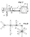
- figure 7 is an elevation view of several components in assembled condition, and
- figure 8 is a diagrammatic plan view of the equipment as installed according to an optional layout.
- the lighting installation shown in the drawings is made up of boxes generally referred to with 1 and formed of two profiled members 2 and 3, of generally channeled shape and mutually complementary, the edges of the said members having sets of ribs and grooves 4 for their mutual pressure fitting (Fig. 2).
- the profiled member 3 may be translucent in the case that a luminous tube is housed therein.
- a lid 7 is engaged at each end of the boxes 1 and is formed with ribs 8 for guiding their position, as well as holes 9 through which screws 10 are passed for screw threaded engagement with the ends 5a of the grooves 5, in order to secure the lids.
- the outer face of the lids 7 has two mutually complementary, diametrically opposite half-sleeves 11 and 12 of different radius, which surround sets of mutually complementary sleeves or tubular housings 13 and 14 which receive, respectively, connection sockets 15 and pins 16 provided with tongues 17 directed towards the center of a central opening 18 of the respective lid for connecting to the electric installation cables.
- the half-sleeves 11 have pairs of semicircular, complementary and opposite cutouts 19 and 20 which mate with one another when the half-sleeves of one lid are fitted or assembled with those of a like lid (Fig. 5).
- the openings formed by the mated cutouts 19 and 20 serve to form a passageway for locking pins 21 and 22 having axial holes through which supporting cables or struts 23 can be inserted.
- the locking pins 21,22 play the role of a linkage between two contiguous lids and ensure the stillness of these later.
- the equipment comprises as well terminal lids 25 having an outline which is analogous to that of the lids 7, and a small closed outer box 26 of a shape similar to that of the half-sleeves 11 and 12, and formed with openings 27 which are similar to the openings 19 and 20 to provide for the insertion of locking pins 21 and 22 in order to secure the ends of suspending struts 23.
- the half-sleeves 11 and 12 are located offset 90° as regards their usual position, for example as indicated with doted lines in figure 3, to place a box 1a in a position which is offset 90° as regards the other boxes (Fig. 6 and 7).
- the equipment comprises as well distribution or junction bodies 28 provided with connection sleeves 29 having a shape which is complementary to that of the half-sleeves 11 and 12 of the assembly lids 7, and provided with electric connection sockets and pins.
- the connection sleeves 29 have a tail 30 shaped so that it can be removably trapped in the junction body 28 and allow the sleeve 29 to be placed in the suitable position.
- the body 28 can trap two or more tails 30 of respective sleeves 29, according to the needs of the installation (Fig. 8).
- the above junction body 28 comprises means for securing a suspending strut 23, as well as for mounting a swinging spotlight 31 of a conventional shape (Fig. 6).
- the lighting installation allows multiple combinations to be effected in order to attain an illumination layout which is distributed in a manner suitable to the features of the site to be lighted, starting from a small series of invariable components featuring an ability for being assembled in different ways.
- This equipment can be completed with an articulation device joined to the profiled members so that these latter can be directed in whatever direction. It is foreseen as well a flexible articulation that can be assembled to the profiled members in order to place the luminous tubes in a vertical plane.
Landscapes
- Engineering & Computer Science (AREA)
- General Engineering & Computer Science (AREA)
- Circuit Arrangement For Electric Light Sources In General (AREA)
- Non-Portable Lighting Devices Or Systems Thereof (AREA)
- Fastening Of Light Sources Or Lamp Holders (AREA)
Claims (10)
- Beleuchtungsvorrichtung, bestehend aus zahlreichen Beleuchtungseinheiten (1), die aufgrund von speziellen Enddeckeln (7) jeder Einheit (1) und speziellen Zwischenverteilungsanschlüssen (28, 29) in verschiedener Weise zusammensetzbar sind, wobei jede Einheit (1) zwei komplementäre Kanalprofilelemente (2, 3) mit einer Einrichtung zum gegenseitigen Eingriff (4) zwecks Bildung eines kastenähnlichen hohlen Gehäuses besitzt, wobei die Deckel (7) und die Zwischenverteilungsanschlüsse mit einer Einrichtung zur mechanischen Verbindung von zwei oder mehreren Einheiten (1) in zahlreichen gewünschten Ausbildungsformen versehen sind,
dadurch gekennzeichnet,
daß die Enddeckel (7) und die Zwischenverteilungsanschlüsse (28, 29) weiterhin eine Einrichtung zur elektrischen Verbindung (15, 16) zweier oder mehrerer benachbarter Einheiten aufweisen, wobei die Einrichtung zur mechanischen Verbindung an den Außenseiten der Enddeckel (7) und der Zwischenverteilungsanschlüsse (28, 29) wechselseitig komplementäre und nach außen vorstehende Halbhülsen (11, 12) aufweisen, die zwei Gruppen von vorstehenden rohrförmigen Gehäuse (13, 14) für die elektrische Verbindungseinrichtung (15, 16) in Form von Anschlußdosen (15) und Steckern (16) umgeben, wobei die Dose und die Stecker eines Enddeckels (7) bzw. Zwischenverteilungsanschlusses (28, 29) mit denen eines benachbarten Deckels bzw. Anschlusses in Eingriff sind und wobei gleichzeitig die Halbhülsen (11, 12) und die beiden Gruppen vorstehender rohrförmiger Gehäuse (13, 14) benachbarter Deckel bzw. Anschlüsse miteinander zu ihrer Montage gekoppelt sind. - Beleuchtungsvorrichtung nach Anspruch 1,
dadurch gekennzeichnet,
daß die kastenähnlichen hohlen Gehäuse (1) eine Einrichtung (5, 6) aufweisen, durch die innerhalb derselben elektrische Komponenten zum Halten und Speisen von Lampen befestigbar sind. - Beleuchtungsvorrichtung nach Anspruch 1,
dadurch gekennzeichnet,
daß wenigstens eines der Kanalprofilelemente (2, 3), das das kastenähnliche hohle Gehäuse (1) bildet, lichtdurchlässig ist. - Beleuchtungsvorrichtung nach Anspruch 1 und 2,
dadurch gekennzeichnet,
daß die komplementären Profilelemente (2, 3), die die kastenähnlichen Gehäuse (1) bilden, innere Nuten (5) besitzen, in denen elektrische Ausrüstungskomponenten mittels Schrauben befestigt sind, und daß die Enden (5a) dieser Nuten die Deckelbefestigungsschrauben (10) in schraubenden Eingriff nehmen. - Beleuchtungsvorrichtung nach Anspruch 1 und 2,
dadurch gekennzeichnet,
daß wenigstens eines der profilierten Elemente (2, 3) in Längsrichtung verlaufende Innenlippen (6a) zur Unterbringung elektrischer Kabel aufweist. - Beleuchtungsvorrichtung nach Anspruch 1,
dadurch gekennzeichnet,
daß gemäß einem speziellen Ausführungsbeispiel jeder Montagedeckel (7) und jedes Gehäuse, das Bezug zu dem Verteilungsanschluß (28, 29) besitzt, zwei gegenüberliegende Halbhülsen (11, 12) unterschiedlicher Durchmesser und in einstellbarer Form aufweist, wobei die Enden der Halbhülsen mit größerem Durchmesser (11) mit halbkreisförmigen Ausschnitten (19, 20) versehen sind, die zu den Ausschnitten (19, 20) der größeren Halbhülsen (11) des anderen Montagedeckels (7) bzw. Gehäuses (28, 29) passen, wenn die beiden Halbhülsen (11) miteinander im Eingriff sind, wobei die Ausschnitte (19, 20) zusammen Durchgangswege für einen entfernbaren Verriegelungsbolzen (21, 22) bilden, der die Verbindung der beiden zusammengesetzen Gehäuse gewährleistet. - Beleuchtungsvorrichtung nach Anspruch 1,
dadurch gekennzeichnet,
daß die beiden Enddeckel (25) eine äußere kastenförmige vorstehende Anformung (26) mit diametral gegenüberliegenden Öffnungen (27) besitzen, in denen ein entfernbarer Verriegelungsbolzen (21, 22), vorteilhaft rohrförmig, befestigbar ist. - Beleuchtungsvorrichtung nach Anspruch 1 und 7,
dadurch gekennzeichnet,
daß die entfernbaren Verriegelungsbolzen (21, 22) einen rohrförmigen Aufbau besitzen. - Beleuchtungsvorrichtung nach Anspruch 1, 7 und 8,
dadurch gekennzeichnet,
daß die rohrförmigen Verriegelungsbolzen (21, 22) eine Einrichtung zur Befestigung von Aufhängungselementen (23) aufweist. - Beleuchtungsvorrichtung nach Anspruch 1,
dadurch gekennzeichnet,
daß einige der Deckel (7), die mit den Enden der profilierten Elemente (2, 3) in Eingriff bringbar sind, Montage- und Verbindungseinrichtungen (11, 12) besitzen, die in einem Winkel bezüglich der Stellung versetzt sind, die diese Einrichtungen bei den verbleibenden Deckeln besitzen.
Priority Applications (1)
| Application Number | Priority Date | Filing Date | Title |
|---|---|---|---|
| AT87500014T ATE85680T1 (de) | 1986-04-09 | 1987-04-07 | Beleuchtungssystem mit mehreren beleuchtungseinheiten. |
Applications Claiming Priority (2)
| Application Number | Priority Date | Filing Date | Title |
|---|---|---|---|
| ES1986293470U ES293470Y (es) | 1986-04-09 | 1986-04-09 | Equipo de componentes ensamblables para iluminacion |
| ES293470 | 1986-04-09 |
Publications (3)
| Publication Number | Publication Date |
|---|---|
| EP0241402A2 EP0241402A2 (de) | 1987-10-14 |
| EP0241402A3 EP0241402A3 (en) | 1989-04-05 |
| EP0241402B1 true EP0241402B1 (de) | 1993-02-10 |
Family
ID=8440584
Family Applications (1)
| Application Number | Title | Priority Date | Filing Date |
|---|---|---|---|
| EP87500014A Expired - Lifetime EP0241402B1 (de) | 1986-04-09 | 1987-04-07 | Beleuchtungssystem mit mehreren Beleuchtungseinheiten |
Country Status (4)
| Country | Link |
|---|---|
| EP (1) | EP0241402B1 (de) |
| AT (1) | ATE85680T1 (de) |
| DE (1) | DE3784089T2 (de) |
| ES (1) | ES293470Y (de) |
Families Citing this family (3)
| Publication number | Priority date | Publication date | Assignee | Title |
|---|---|---|---|---|
| DE3912299A1 (de) * | 1989-04-14 | 1990-11-29 | Joerg Michael Uhl | Leuchtroehrenanordnungs- und betriebssystem |
| DE19719184C1 (de) * | 1997-05-06 | 1998-10-08 | Keller Lichtsysteme Gmbh | Leuchte |
| DE10139336B4 (de) * | 2001-08-10 | 2012-04-26 | Hartmut S. Engel | Modulares Leuchtensystem |
Family Cites Families (5)
| Publication number | Priority date | Publication date | Assignee | Title |
|---|---|---|---|---|
| GB561090A (en) * | 1942-01-07 | 1944-05-04 | Darwin Curtis | Improvements in electric lighting fixtures |
| AT308239B (de) * | 1970-07-08 | 1973-06-25 | Anton Brenner Ing | Leuchtkörper |
| DE2556813B2 (de) * | 1975-12-17 | 1979-12-13 | Wolfgang 6204 Taunusstein Fenner | Raumfachwerk |
| US4096379A (en) * | 1976-08-24 | 1978-06-20 | Albert Taylor | Modular illumination device |
| DE3014241A1 (de) * | 1980-04-14 | 1981-11-12 | Trilux-Lenze Gmbh + Co Kg, 5760 Arnsberg | Vorrichtung zum verbinden von leuchten zu lichtbaendern bzw. lichtbandfiguren |
-
1986
- 1986-04-09 ES ES1986293470U patent/ES293470Y/es not_active Expired
-
1987
- 1987-04-07 AT AT87500014T patent/ATE85680T1/de not_active IP Right Cessation
- 1987-04-07 DE DE8787500014T patent/DE3784089T2/de not_active Expired - Fee Related
- 1987-04-07 EP EP87500014A patent/EP0241402B1/de not_active Expired - Lifetime
Also Published As
| Publication number | Publication date |
|---|---|
| ATE85680T1 (de) | 1993-02-15 |
| ES293470U (es) | 1986-08-01 |
| EP0241402A2 (de) | 1987-10-14 |
| DE3784089D1 (de) | 1993-03-25 |
| DE3784089T2 (de) | 1993-08-05 |
| EP0241402A3 (en) | 1989-04-05 |
| ES293470Y (es) | 1987-04-16 |
Similar Documents
| Publication | Publication Date | Title |
|---|---|---|
| US7293895B2 (en) | Modular lighting system and method of installation | |
| US2988633A (en) | Fluorescent ceiling light fixture assembly | |
| US5073845A (en) | Fluorescent retrofit light fixture | |
| US5599091A (en) | Landscape lighting fixture | |
| MXPA05004885A (es) | Sistema de luminaria modular. | |
| US3999160A (en) | Modular traffic signal apparatus | |
| US5751117A (en) | Modular fluorescent track lighting | |
| EP0138746B1 (de) | Leuchte mit begleitender linearer Lichtquelle | |
| AU652050B2 (en) | Line illumination device and mounting member for this device | |
| US5420764A (en) | Socket/tab supported light fixture | |
| EP0241402B1 (de) | Beleuchtungssystem mit mehreren Beleuchtungseinheiten | |
| US5709461A (en) | Electrical concertina-type lamp | |
| US5169227A (en) | Fluorescent lamp | |
| CA2089444A1 (en) | Two-piece locking lamp fixture | |
| US4929192A (en) | Connection and fixing system for electronic unit | |
| US2964616A (en) | Lighting fixture | |
| EP0396784A1 (de) | Schnell-Spannsystem für kompletten Beleuchtungskörper zum Schnell-Spannen von Glühbirnen, Lampenschirme und Beleuchtungskörper | |
| EP0469179B1 (de) | Modulares Leuchtensystem | |
| EP1016818A3 (de) | Lampenfassung aus Isolierstoff für H 7-Lampen | |
| US3465282A (en) | Light fitting | |
| US6413107B1 (en) | Lamp | |
| GB2064089A (en) | Improvements in or relating to lighting apparatus | |
| US3018363A (en) | Lighting fixture | |
| DE59403375D1 (de) | Leuchte | |
| EP0151674A2 (de) | Wohn- und/oder Arbeitsleuchte |
Legal Events
| Date | Code | Title | Description |
|---|---|---|---|
| PUAI | Public reference made under article 153(3) epc to a published international application that has entered the european phase |
Free format text: ORIGINAL CODE: 0009012 |
|
| AK | Designated contracting states |
Kind code of ref document: A2 Designated state(s): AT BE CH DE FR GB GR IT LI LU NL SE |
|
| PUAL | Search report despatched |
Free format text: ORIGINAL CODE: 0009013 |
|
| AK | Designated contracting states |
Kind code of ref document: A3 Designated state(s): AT BE CH DE FR GB GR IT LI LU NL SE |
|
| 17P | Request for examination filed |
Effective date: 19891006 |
|
| 17Q | First examination report despatched |
Effective date: 19910822 |
|
| RTI1 | Title (correction) | ||
| GRAA | (expected) grant |
Free format text: ORIGINAL CODE: 0009210 |
|
| AK | Designated contracting states |
Kind code of ref document: B1 Designated state(s): AT BE CH DE FR GB GR IT LI LU NL SE |
|
| REF | Corresponds to: |
Ref document number: 85680 Country of ref document: AT Date of ref document: 19930215 Kind code of ref document: T |
|
| REF | Corresponds to: |
Ref document number: 3784089 Country of ref document: DE Date of ref document: 19930325 |
|
| PGFP | Annual fee paid to national office [announced via postgrant information from national office to epo] |
Ref country code: SE Payment date: 19930413 Year of fee payment: 7 |
|
| PGFP | Annual fee paid to national office [announced via postgrant information from national office to epo] |
Ref country code: DE Payment date: 19930419 Year of fee payment: 7 Ref country code: AT Payment date: 19930419 Year of fee payment: 7 |
|
| PGFP | Annual fee paid to national office [announced via postgrant information from national office to epo] |
Ref country code: LU Payment date: 19930421 Year of fee payment: 7 |
|
| PGFP | Annual fee paid to national office [announced via postgrant information from national office to epo] |
Ref country code: FR Payment date: 19930429 Year of fee payment: 7 |
|
| PGFP | Annual fee paid to national office [announced via postgrant information from national office to epo] |
Ref country code: NL Payment date: 19930430 Year of fee payment: 7 Ref country code: GB Payment date: 19930430 Year of fee payment: 7 |
|
| ITF | It: translation for a ep patent filed | ||
| PGFP | Annual fee paid to national office [announced via postgrant information from national office to epo] |
Ref country code: BE Payment date: 19930504 Year of fee payment: 7 |
|
| PGFP | Annual fee paid to national office [announced via postgrant information from national office to epo] |
Ref country code: GR Payment date: 19930510 Year of fee payment: 7 |
|
| PGFP | Annual fee paid to national office [announced via postgrant information from national office to epo] |
Ref country code: CH Payment date: 19930527 Year of fee payment: 7 |
|
| ET | Fr: translation filed | ||
| REG | Reference to a national code |
Ref country code: GR Ref legal event code: FG4A Free format text: 3007786 |
|
| EPTA | Lu: last paid annual fee | ||
| PLBE | No opposition filed within time limit |
Free format text: ORIGINAL CODE: 0009261 |
|
| STAA | Information on the status of an ep patent application or granted ep patent |
Free format text: STATUS: NO OPPOSITION FILED WITHIN TIME LIMIT |
|
| 26N | No opposition filed | ||
| PG25 | Lapsed in a contracting state [announced via postgrant information from national office to epo] |
Ref country code: LU Free format text: LAPSE BECAUSE OF NON-PAYMENT OF DUE FEES Effective date: 19940407 Ref country code: GB Effective date: 19940407 Ref country code: AT Effective date: 19940407 |
|
| PG25 | Lapsed in a contracting state [announced via postgrant information from national office to epo] |
Ref country code: SE Effective date: 19940408 |
|
| PG25 | Lapsed in a contracting state [announced via postgrant information from national office to epo] |
Ref country code: LI Effective date: 19940430 Ref country code: CH Effective date: 19940430 Ref country code: BE Effective date: 19940430 |
|
| BERE | Be: lapsed |
Owner name: S.A. J. FELIU DE LA PENA Effective date: 19940430 |
|
| PG25 | Lapsed in a contracting state [announced via postgrant information from national office to epo] |
Ref country code: GR Free format text: THE PATENT HAS BEEN ANNULLED BY A DECISION OF A NATIONAL AUTHORITY Effective date: 19941031 |
|
| PG25 | Lapsed in a contracting state [announced via postgrant information from national office to epo] |
Ref country code: NL Effective date: 19941101 |
|
| GBPC | Gb: european patent ceased through non-payment of renewal fee |
Effective date: 19940407 |
|
| NLV4 | Nl: lapsed or anulled due to non-payment of the annual fee | ||
| PG25 | Lapsed in a contracting state [announced via postgrant information from national office to epo] |
Ref country code: FR Effective date: 19941229 |
|
| REG | Reference to a national code |
Ref country code: CH Ref legal event code: PL |
|
| PG25 | Lapsed in a contracting state [announced via postgrant information from national office to epo] |
Ref country code: DE Effective date: 19950103 |
|
| EUG | Se: european patent has lapsed |
Ref document number: 87500014.3 Effective date: 19941110 |
|
| REG | Reference to a national code |
Ref country code: FR Ref legal event code: ST |
|
| REG | Reference to a national code |
Ref country code: GR Ref legal event code: MM2A Free format text: 3007786 |
|
| PG25 | Lapsed in a contracting state [announced via postgrant information from national office to epo] |
Ref country code: IT Free format text: LAPSE BECAUSE OF NON-PAYMENT OF DUE FEES;WARNING: LAPSES OF ITALIAN PATENTS WITH EFFECTIVE DATE BEFORE 2007 MAY HAVE OCCURRED AT ANY TIME BEFORE 2007. THE CORRECT EFFECTIVE DATE MAY BE DIFFERENT FROM THE ONE RECORDED. Effective date: 20050407 |