EP0241320B1 - Alternator with a low harmonics rate - Google Patents
Alternator with a low harmonics rate Download PDFInfo
- Publication number
- EP0241320B1 EP0241320B1 EP87400438A EP87400438A EP0241320B1 EP 0241320 B1 EP0241320 B1 EP 0241320B1 EP 87400438 A EP87400438 A EP 87400438A EP 87400438 A EP87400438 A EP 87400438A EP 0241320 B1 EP0241320 B1 EP 0241320B1
- Authority
- EP
- European Patent Office
- Prior art keywords
- alternator
- winding
- pole
- corrector
- armature
- Prior art date
- Legal status (The legal status is an assumption and is not a legal conclusion. Google has not performed a legal analysis and makes no representation as to the accuracy of the status listed.)
- Expired - Lifetime
Links
Images
Classifications
-
- H—ELECTRICITY
- H02—GENERATION; CONVERSION OR DISTRIBUTION OF ELECTRIC POWER
- H02K—DYNAMO-ELECTRIC MACHINES
- H02K3/00—Details of windings
- H02K3/04—Windings characterised by the conductor shape, form or construction, e.g. with bar conductors
- H02K3/18—Windings for salient poles
- H02K3/20—Windings for salient poles for auxiliary purposes, e.g. damping or commutating
Definitions
- the present invention relates to an alternator with a low harmonic ratio.
- the armature reaction field which arises in the armature of an alternator as a result of the current flowing there presents, relative to the inductor, a direct component and an inverse component, the component inverse having a frequency twice that of the current flowing in the armature.
- the inverse component of the armature reaction field induces in the windings of the inductor an electromotive force and a frequency current double that of the current flowing in the armature.
- This generates a so-called "reflected" field which causes, in the magnetic circuit of the inductor, additional iron losses which increase the heating in service of the alternator.
- This reflected field also induces, on the stator, an electromotive force of frequency three times that of the current flowing in the armature, which further increases the harmonic rate of order 3.
- this harmonic of order 3 is particularly detrimental to the proper functioning of certain types of powered devices.
- the object of the invention is thus to propose a single-phase alternator whose output voltage has a harmonic ratio of order 3 as reduced as possible, regardless of the nature of the armature winding.
- the single-phase alternator which comprises an armature provided with at least one armature winding and an inductor which comprises on the one hand a magnetic circuit having at least one pair of poles laterally carrying polar horns and on the other hand at least one excitation winding formed around the magnetic circuit, the inductor and the armature being movable in rotation relative to each other, is characterized in that at least one of the poles present at in the vicinity of at least one of its polar horns a notch occupied by a corrective winding which embraces said polar horn and the ends of which are connected to the terminals of a diode so that the corrective winding is traversed in service by a current substantially continued.
- the substantially direct current which flows through the corrective winding gives rise to a magnetic field modifying the saturation of the polar horns which are surrounded by this corrective winding.
- This modification of the state of saturation of the polar horns influences the fields generated in the armature which close in the polar horns. This results in modifications of the magnetic fluxes in the armature, in a direction reducing the proportion of harmonic of order 3.
- the ends of the corrector winding are connected to the terminals of a diode.
- the reverse component during its passage through the inductor, induces at the terminals of the correcting winding an electromotive force giving rise in this correcting winding to a current which is rectified by the diode.
- This current which can be assimilated to a direct current induces a continuous magnetic field which tends to modify the state of saturation of the polar horn (s) surrounded by said winding.
- the existence of the inverse component in the inductor is exploited to spontaneously generate the current which is needed in the correcting winding.
- the axis of the corrector winding is substantially perpendicular to the axis of the poles.
- the correcting winding thus optimally collects the induction effect of the reverse field.
- a single-phase alternator comprising an armature 1 provided with an armature winding 2 connected to the terminals of a load 15 and an inductor 3 which comprises a magnetic circuit 4 having a pair of poles 5 each of which laterally carries two opposite polar horns 6.
- Four excitation windings 7 are formed around the magnetic circuit 4 between the two poles 5, according to an axis substantially parallel to the axis XX ′ of the poles 5.
- the inductor 3 and the armature 1 are movable in rotation relative to each other, while, most often, the inductor 3 is the rotor, and the armature 1 is fixed.
- the aforementioned elements are produced and mounted in a conventional manner.
- the inductor 3 further comprises two correcting windings 8 arranged on either side of the axis XX ′ of the poles 5 and each of which surrounds the magnetic circuit 4 in a plane parallel to the axis XX ′ passing through a pair of notches 9 each formed in a different pole 5 so as to open in the substantially cylindrical peripheral surface of this pole.
- Each notch 9 determines a neck 10 between one of the pole horns 6 of the corresponding pole 5 and the rest of the magnetic circuit 4.
- Each corrector winding 8 embraces the two necks 10 adjacent to the two notches 9 which it occupies.
- the axis of the correcting windings 8 is substantially perpendicular to the axis X-X ′ of the poles 5.
- each corrector winding 8 is connected to the terminals of a diode 12.
- the two correcting windings 8 are mounted in series at the terminals of a diode 13.
- the necessary insulations are provided between the excitation windings 7, the correcting windings 8 and the magnetic circuit 4.
- the field generated by the corrective windings is added to the main field produced by the inductive windings in one of the horns of each pole and is subtracted of the main field in the other horn of each pole.
- This modification of the state of saturation of the polar horns deforms the field lines in the armature, and this in a direction reducing the proportion of harmonic of order 3 in the tension produced by the alternator.
- the first case it noted on the voltage wave delivered at the output a harmonic rate of order 3 of the order of 23% while in the second case, the rate measured was only 9 % under identical operating conditions.
- the Applicant has also found that the correcting windings 8 participate in the reduction of iron losses in the magnetic circuit 4 of the inductor 3 and moreover allow better regulation of the output voltage of the alternator as a function of the load.
- the correcting windings can each surround only one of the necks such as 10, that is to say that in the bipolar inductor shown there would be four correcting windings, one around each horn, if all the horns were equipped .
- the correcting windings could each pass through two diametrically opposite notches.
Landscapes
- Engineering & Computer Science (AREA)
- Power Engineering (AREA)
- Synchronous Machinery (AREA)
Description
La présente invention concerne un alternateur à faible taux d'harmoniques.The present invention relates to an alternator with a low harmonic ratio.
Elle vise particulièrement, un alternateur monophasé dont l'inducteur comporte une paire de pôles et non pas un alternateur polyphasé du genre de celui décrit dans l'US-A-4573003.It particularly targets a single-phase alternator whose inductor comprises a pair of poles and not a polyphase alternator of the type described in US-A-4573003.
Comme l'on sait, le champ de réaction d'induit qui prend naissance dans l'induit d'un alternateur en conséquence du courant qui y circule présente, par rapport à l'inducteur, une composante directe et une composante inverse, la composante inverse ayant une fréquence double de celle du courant circulant dans l'induit.As we know, the armature reaction field which arises in the armature of an alternator as a result of the current flowing there presents, relative to the inductor, a direct component and an inverse component, the component inverse having a frequency twice that of the current flowing in the armature.
La saturation des cornes polaires due à la composante directe du champ de réaction d'induit provoque une déformation de la répartition du flux magnétique dans l'entrefer. Ceci contribue à induire dans les enroulements de l'induit une force électromotrice contenant une forte proportion d'harmonique d'ordre 3.The saturation of the polar horns due to the direct component of the armature reaction field causes a distortion of the distribution of the magnetic flux in the air gap. This contributes to inducing in the windings of the armature an electromotive force containing a high proportion of harmonic of order 3.
De plus, dans les alternateurs monophasés, la composante inverse du champ de réaction d'induit induit dans les enroulements de l'inducteur une force électromotrice et un courant de fréquence double de celle du courant circulant dans l'induit. Ceci génère un champ dit "réfléchi" qui provoque, dans le circuit magnétique de l'inducteur, des pertes fer supplémentaires qui augmentent l'échauffement en service de l'alternateur. Ce champ réfléchi induit en outre, au stator, une force électromotrice de fréquence triple de celle du courant circulant dans l'induit, ce qui accroît encore le taux d'harmonique d'ordre 3. Or, cette harmonique d'ordre 3 est particulièrement préjudiciable au bon fonctionnement de certains types d'appareils alimentés.In addition, in single-phase alternators, the inverse component of the armature reaction field induces in the windings of the inductor an electromotive force and a frequency current double that of the current flowing in the armature. This generates a so-called "reflected" field which causes, in the magnetic circuit of the inductor, additional iron losses which increase the heating in service of the alternator. This reflected field also induces, on the stator, an electromotive force of frequency three times that of the current flowing in the armature, which further increases the harmonic rate of order 3. Now, this harmonic of order 3 is particularly detrimental to the proper functioning of certain types of powered devices.
Afin de réduire la proportion d'harmonique d'ordre 3 dans la force électromotrice de l'induit, certains constructeurs proposent de bobiner l'induit de l'alternateur avec un enroulement spécial à pas raccourci. Toutefois, cette solution est coûteuse et conduit à la fabrication de machines dites spéciales qui doivent être en outre le plus souvent déclassées.In order to reduce the proportion of order 3 harmonics in the electromotive force of the armature, some manufacturers offer to wind the armature of the alternator with a special winding with shortened pitch. However, this solution is expensive and leads to the manufacture of so-called special machines which must moreover most often be decommissioned.
Le but de l'invention est ainsi de proposer un alternateur monophasé dont la tension de sortie présente un taux d'harmonique d'ordre 3 aussi réduit que possible, indépendamment de la nature du bobinage de l'induit.The object of the invention is thus to propose a single-phase alternator whose output voltage has a harmonic ratio of order 3 as reduced as possible, regardless of the nature of the armature winding.
Selon l'invention, l'alternateur monophasé qui comporte un induit muni d'au moins un enroulement d'induit et un inducteur qui comprend d'une part un circuit magnétique présentant au moins une paire de pôles portant latéralement des cornes polaires et d'autre part au moins un enroulement d'excitation formé autour du circuit magnétique, l'inducteur et l'induit étant mobiles en rotation l'un par rapport à l'autre, est caractérisé en ce que l'un au moins des pôles présente au voisinage de l'une au moins de ses cornes polaires une encoche occupée par un enroulement correcteur qui embrasse ladite corne polaire et dont les extrémités sont raccordées aux bornes d'une diode de façon que l'enroulement correcteur soit parcouru en service par un courant sensiblement continu.According to the invention, the single-phase alternator which comprises an armature provided with at least one armature winding and an inductor which comprises on the one hand a magnetic circuit having at least one pair of poles laterally carrying polar horns and on the other hand at least one excitation winding formed around the magnetic circuit, the inductor and the armature being movable in rotation relative to each other, is characterized in that at least one of the poles present at in the vicinity of at least one of its polar horns a notch occupied by a corrective winding which embraces said polar horn and the ends of which are connected to the terminals of a diode so that the corrective winding is traversed in service by a current substantially continued.
Le courant sensiblement continu qui parcourt l'enroulement correcteur donne naissance à un champ magnétique modifiant la saturation des cornes polaires qui sont entourées par cet enroulement correcteur. Cette modification de l'état de saturation des cornes polaires influe sur les champs générés dans l'induit qui se referment dans les cornes polaires. Ceci se traduit par des modifications des flux magnétiques dans l'induit, dans un sens réduisant la proportion d'harmonique d'ordre 3.The substantially direct current which flows through the corrective winding gives rise to a magnetic field modifying the saturation of the polar horns which are surrounded by this corrective winding. This modification of the state of saturation of the polar horns influences the fields generated in the armature which close in the polar horns. This results in modifications of the magnetic fluxes in the armature, in a direction reducing the proportion of harmonic of order 3.
L'enroulement correcteur participe également à la réduction des pertes fer dans le circuit magnétique de l'inducteur car il permet d'affaiblir le champ inverse. Il a de plus été constaté que les courbes de l'intensité du courant de sortie en fonction de l'intensité du courant d'excitation à cos ![]()
![]()
![]()
![]()
Suivant un mode de réalisation avantageux de l'invention, qui concerne un alternateur monophasé, les extrémités de l'enroulement correcteur sont raccordées aux bornes d'une diode.According to an advantageous embodiment of the invention, which relates to a single-phase alternator, the ends of the corrector winding are connected to the terminals of a diode.
La composante inverse, lors de son passage par l'inducteur, induit aux bornes de l'enroulement correcteur une force électromotrice donnant naissance dans cet enroulement correcteur à un courant qui est redressé par la diode. Ce courant qui est assimilable à un courant continu induit un champ magnétique continu qui tend à modifier l'état de saturation de la ou des corne(s) polaire(s) entourée(s) par ledit enroulement. Ainsi, dans le cas d'un alternateur monophasé, on exploite l'existence de la composante inverse dans l'inducteur pour générer spontanément le courant dont on a besoin dans l'enroulement correcteur.The reverse component, during its passage through the inductor, induces at the terminals of the correcting winding an electromotive force giving rise in this correcting winding to a current which is rectified by the diode. This current which can be assimilated to a direct current induces a continuous magnetic field which tends to modify the state of saturation of the polar horn (s) surrounded by said winding. Thus, in the case of a single-phase alternator, the existence of the inverse component in the inductor is exploited to spontaneously generate the current which is needed in the correcting winding.
De préférence, l'axe de l'enroulement correcteur est sensiblement perpendiculaire à l'axe des pôles.Preferably, the axis of the corrector winding is substantially perpendicular to the axis of the poles.
L'enroulement correcteur recueille ainsi de façon optimale l'effet d'induction du champ inverse.The correcting winding thus optimally collects the induction effect of the reverse field.
D'autres particularités de l'invention résulteront encore de la description qui va suivre.Other features of the invention will also emerge from the description which follows.
Aux dessins annexés, donnés à titre d'exemples non limitatifs:
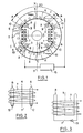
- la figure 1 est une vue en coupe schématique d'un alternateur monophasé bipolaire conforme à l'invention,
- la figure 2 est un schéma de principe du circuit électrique de l'inducteur de la figure 1, et
- la figure 3 est un schéma analogue au précédent mais concernant une variante de réalisation.
- FIG. 1 is a schematic sectional view of a bipolar single-phase alternator according to the invention,
- FIG. 2 is a block diagram of the electrical circuit of the inductor of FIG. 1, and
- Figure 3 is a diagram similar to the previous but relating to an alternative embodiment.
A la figure 1, on a représenté un alternateur monophasé comportant un induit 1 muni d'un enroulement 2 d'induit raccordé aux bornes d'une charge 15 et un inducteur 3 qui comprend un circuit magnétique 4 présentant une paire de pôles 5 dont chacun porte latéralement deux cornes polaires opposées 6. Quatre enroulements d'excitation 7 sont formés autour du circuit magnétique 4 entre les deux pôles 5, selon un axe sensiblement parallèle à l'axe X-X′ des pôles 5. L'inducteur 3 et l'induit 1 sont mobiles en rotation l'un par rapport à l'autre, tandis que, le plus souvent, l'inducteur 3 est le rotor, et l'induit 1 est fixe.In Figure 1, there is shown a single-phase alternator comprising an armature 1 provided with an armature winding 2 connected to the terminals of a
Les éléments précités sont réalisés et montés de manière classique.The aforementioned elements are produced and mounted in a conventional manner.
Suivant l'invention, l'inducteur 3 comprend en outre deux enroulements correcteurs 8 disposés de part et d'autre de l'axe X-X′ des pôles 5 et dont chacun entoure le circuit magnétique 4 dans un plan parallèle à l'axe X-X′ en passant dans une paire d'encoches 9 formées chacune dans un pôle différent 5 de manière à s'ouvrir dans la surface périphérique sensiblement cylindrique de ce pôle. Chaque encoche 9 détermine un col 10 entre l'une des cornes polaires 6 du pôle 5 correspondant et le reste du circuit magnétique 4. Chaque enroulement correcteur 8 embrasse les deux cols 10 adjacents aux deux encoches 9 qu'il occupe.According to the invention, the inductor 3 further comprises two correcting
L'axe des enroulements correcteurs 8 est sensiblement perpendiculaire à l'axe X-X′ des pôles 5.The axis of the correcting
Comme le montre la figure 2, les extrémités de chaque enroulement correcteur 8 sont raccordées aux bornes d'une diode 12.As shown in FIG. 2, the ends of each corrector winding 8 are connected to the terminals of a
Dans la variante de réalisation selon la figure 3, les deux enroulements correcteurs 8 sont montés en série aux bornes d'une diode 13.In the variant embodiment according to FIG. 3, the two correcting
Les isolations nécessaires sont prévues entre les enroulements d'excitation 7, les enroulements correcteurs 8 et le circuit magnétique 4.The necessary insulations are provided between the
Le fonctionnement du présent alternateur est le suivant:The operation of this alternator is as follows:
Lorsque l'inducteur 3 est excité par alimentation de ses enroulements d'excitation 7 au moyen d'un courant continu d'intensité appropriée et que l'enroulement 2 de l'induit 1 est raccordé aux bornes de la charge 15, les ampères-tours de réaction d'induit donnent naissance à un champ magnétique qui présente une composante paire, dite champ inverse, de fréquence double de la fréquence nominale.When the inductor 3 is excited by supplying its
Une partie de ce champ inverse pénètre dans le circuit magnétique 4 de l'inducteur 3 par les cornes polaires 6 en traversant les enroulements correcteurs 8 et induit aux bornes de ces enroulements correcteurs 8 une force électromotrice qui donne naissance dans les enroulements correcteurs 8 à un courant qui est redressé par la diode 12, 13 raccordée aux bornes de ces enroulements 8. Ce courant redressé, assimilable à un courant continu, génère un champ magnétique continu d'autosaturation (c'est-à-dire ne nécessitant pas d'alimentation en courant auxiliaire) des cornes polaires 6 qui sont entourées par les enroulements correcteurs 8. Plus précisément, le champ généré par les enroulements correcteurs s'ajoute au champ principal produit par les enroulements inducteurs dans l'une des cornes de chaque pôle et se retranche du champ principal dans l'autre corne de chaque pôle. Cette modification de l'état de saturation des cornes polaires déforme les lignes de champ dans l'induit, et ceci dans un sens réduisant la proportion d'harmonique d'ordre 3 dans la tension produite par l'alternateur.Part of this reverse field enters the
La demanderesse a conduit des essais comparatifs sur deux alternateurs monophasés bipolaires 6 kvA, 50 Hz, 3000 t/mn à cos ![]()
![]()
La demanderesse à également constaté que les enroulements correcteurs 8 participaient à la réduction des pertes fer dans le circuit magnétique 4 de l'inducteur 3 et autorisaient de plus une meilleure régulation de la tension de sortie de l'alternateur en fonction de la charge.The Applicant has also found that the correcting
Des essais complémentaires ont démontré qu'une correction optimale était obtenue avec:
- chaque pôle s'étendant sur un angle sensiblement égal à 120° et l'arc compris entre les milieux des deux
encoches 9 d'unmême pôle 5 ayant un angle sensiblement égal à 90°; - une section d'encoche maximale qui tienne compte cependant des harmoniques supplémentaires engendrées par la présence de ces encoches lors du fonctionnement à vide de l'alternateur. Cette section d'encoches peut être choisie par exemple de sorte que le taux d'harmonique individuelle à vide ne dépasse pas 2%;
- une ouverture (e) d'encoche minimale déterminée en fonction du diamètre des fils constitutifs de l'enroulement correcteur et de la tenue mécanique du
bec 16 formé par cette ouverture; - pour chaque
pôle 5, une section de passage 2a du flux magnétique principal dans les cornes polaires 6 au moins égale à 20% de la section depassage 2D de ce flux principal délimitée entre les deuxencoches 9 du pôle considéré 5.
- each pole extending over an angle substantially equal to 120 ° and the arc included between the midpoints of the two
notches 9 of thesame pole 5 having an angle substantially equal to 90 °; - a maximum notch section which nevertheless takes account of the additional harmonics generated by the presence of these notches during the no-load operation of the alternator. This section of notches can be chosen, for example, so that the individual void harmonic rate does not exceed 2%;
- a minimum notch opening ( e ) determined as a function of the diameter of the wires making up the corrector winding and the mechanical strength of the
spout 16 formed by this opening; - for each
pole 5, a passage section 2a of the main magnetic flux in thepolar horns 6 at least equal to 20% of the 2D passage section of this main flux delimited between the twonotches 9 of the pole considered 5.
Bien entendu, l'invention n'est pas limitée à l'exemple que l'on vient de décrire.Of course, the invention is not limited to the example which has just been described.
En particulier, les enroulements correcteurs peuvent entourer chacun un seul des cols tels que 10, c'est-à-dire que dans l'inducteur bipolaire représenté il y aurait quatre enroulements correcteurs, un autour de chaque corne, si toutes les cornes étaient équipées.In particular, the correcting windings can each surround only one of the necks such as 10, that is to say that in the bipolar inductor shown there would be four correcting windings, one around each horn, if all the horns were equipped .
Dans un autre mode de réalisation, les enroulements correcteurs pourraient passer chacun dans deux encoches diamétralement opposées.In another embodiment, the correcting windings could each pass through two diametrically opposite notches.
Claims (9)
Applications Claiming Priority (2)
| Application Number | Priority Date | Filing Date | Title |
|---|---|---|---|
| FR8603235A FR2595517B1 (en) | 1986-03-07 | 1986-03-07 | LOW HARMONIC ALTERNATOR |
| FR8603235 | 1986-03-07 |
Publications (2)
| Publication Number | Publication Date |
|---|---|
| EP0241320A1 EP0241320A1 (en) | 1987-10-14 |
| EP0241320B1 true EP0241320B1 (en) | 1991-06-05 |
Family
ID=9332872
Family Applications (1)
| Application Number | Title | Priority Date | Filing Date |
|---|---|---|---|
| EP87400438A Expired - Lifetime EP0241320B1 (en) | 1986-03-07 | 1987-02-27 | Alternator with a low harmonics rate |
Country Status (7)
| Country | Link |
|---|---|
| US (1) | US4780633A (en) |
| EP (1) | EP0241320B1 (en) |
| JP (1) | JPS62268341A (en) |
| AU (1) | AU592160B2 (en) |
| DE (1) | DE3770509D1 (en) |
| ES (1) | ES2022387B3 (en) |
| FR (1) | FR2595517B1 (en) |
Families Citing this family (3)
| Publication number | Priority date | Publication date | Assignee | Title |
|---|---|---|---|---|
| FR2842361A1 (en) * | 2002-07-10 | 2004-01-16 | Leroy Somer Moteurs | High efficiency alternators having magnetic body with winding and shock absorbers carrying electrical conductor through holes perpendicular rotation axis. |
| US20140368075A1 (en) * | 2013-06-12 | 2014-12-18 | Hamilton Sundstrand Corporation | Permanent magnet synchronous machines with magnetic flux regulation |
| CN105610255A (en) * | 2016-03-01 | 2016-05-25 | 中车株洲电力机车研究所有限公司 | Rotor device of electrically excited synchronous motor and motor |
Family Cites Families (10)
| Publication number | Priority date | Publication date | Assignee | Title |
|---|---|---|---|---|
| FR364374A (en) * | 1905-03-18 | 1906-08-21 | Oerlikon Maschf | Inductor for synchronous generator of alternating currents with winding forming a screen |
| DE1513819B2 (en) * | 1966-01-21 | 1971-12-02 | Siemens AG, 1000 Berlin u. 8000 München | TWO-POLE INDUCTOR FOR ELECTRIC MACHINERY |
| US4097754A (en) * | 1976-10-20 | 1978-06-27 | Tecumseh Products Company | Short pitch alternator |
| JPS53122714A (en) * | 1977-03-31 | 1978-10-26 | Mitsubishi Electric Corp | Self excitation device for synchronous machine |
| SU830615A1 (en) * | 1979-03-01 | 1981-05-15 | Куйбышевский Политехнический Институтим. B.B.Куйбышева | Dc machine |
| JPS5646651A (en) * | 1979-09-24 | 1981-04-27 | Yamaha Motor Co Ltd | Brushless self-excited synchronizing generator having salient-type rotor |
| US4454465A (en) * | 1981-04-29 | 1984-06-12 | Teledyne Walterboro, A Division Of Teledyne Industries, Inc. | Electric generator that operates with few ampere-turns in field winding |
| IT1157431B (en) * | 1982-02-16 | 1987-02-11 | Mase Elettromeccanica Spa | SINGLE-PHASE ALTERNATOR PERFECTED |
| US4573003A (en) * | 1983-09-30 | 1986-02-25 | Wisconsin Alumni Research Foundation | AC Machine optimized for converter operation |
| JPS60241755A (en) * | 1984-05-12 | 1985-11-30 | Yoshiteru Teraue | Brushless synchronous motor |
-
1986
- 1986-03-07 FR FR8603235A patent/FR2595517B1/en not_active Expired
-
1987
- 1987-02-27 ES ES87400438T patent/ES2022387B3/en not_active Expired - Lifetime
- 1987-02-27 DE DE8787400438T patent/DE3770509D1/en not_active Expired - Lifetime
- 1987-02-27 EP EP87400438A patent/EP0241320B1/en not_active Expired - Lifetime
- 1987-03-03 US US07/022,622 patent/US4780633A/en not_active Expired - Lifetime
- 1987-03-06 AU AU69799/87A patent/AU592160B2/en not_active Ceased
- 1987-03-06 JP JP62050411A patent/JPS62268341A/en active Pending
Also Published As
| Publication number | Publication date |
|---|---|
| EP0241320A1 (en) | 1987-10-14 |
| AU6979987A (en) | 1987-11-12 |
| JPS62268341A (en) | 1987-11-20 |
| AU592160B2 (en) | 1990-01-04 |
| US4780633A (en) | 1988-10-25 |
| ES2022387B3 (en) | 1991-12-01 |
| FR2595517B1 (en) | 1988-06-24 |
| FR2595517A1 (en) | 1987-09-11 |
| DE3770509D1 (en) | 1991-07-11 |
Similar Documents
| Publication | Publication Date | Title |
|---|---|---|
| US6369474B1 (en) | Alternating current generator for vehicle | |
| EP0183576B1 (en) | Permanent magnet rotating machine | |
| US7692341B2 (en) | Compact high power alternator | |
| FR2769422A1 (en) | ELECTRIC FLOW SWITCHING MACHINE, IN PARTICULAR A MOTOR VEHICLE ALTERNATOR | |
| EP0241320B1 (en) | Alternator with a low harmonics rate | |
| EP0080925A1 (en) | Static converter with a twelve-phase circuit of two Graetz bridges for the suppression of the 5th and 7th harmonics in the network | |
| EP0644644B1 (en) | Rotor of synchronous machine | |
| KR20110060781A (en) | Automotive Alternator | |
| WO2021116040A1 (en) | End shield for a rotary electric machine | |
| FR2690291A1 (en) | Alternator with excitation by permanent magnets. | |
| CN1109395C (en) | Two-pole turbine generator and rotor thereof | |
| EP0828335B1 (en) | Motor vehicle generator with three-phase windings | |
| FR2775393A1 (en) | Hybrid vernier(RTM) effect variable reluctance dynamo electric motor having a large range and speed. | |
| RU2109390C1 (en) | Single-phase salient-pole electric motor | |
| FR2767236A1 (en) | ELECTRIC MACHINE, PARTICULARLY THREE-PHASE CURRENT MACHINE | |
| FR2566975A1 (en) | Improvements to rotating electrical machines, in particular to multi-output stand-alone generators | |
| FR2523780A1 (en) | ELECTRICAL POWER GENERATOR EQUIPPED WITH COOLING BLADES WITH A ROTATION SPEED NOT EXCEEDING A CONSTANT VALUE | |
| BE417132A (en) | ||
| FR3150365A1 (en) | Inductive transmission system for transmitting electrical energy to a rotor excitation winding | |
| BE513016A (en) | ||
| FR3142864A1 (en) | Electrical equipment | |
| BE336425A (en) | ||
| JPS59198861A (en) | Ac generator for vehicle | |
| FR3116372A1 (en) | ELECTRICAL DEVICE WITH TWO GROUPS OF COUPLED COILS CARRIED BY A PRINTED CIRCUIT BOARD, VOLTAGE CONVERTER COMPRISING SUCH ELECTRICAL DEVICE AND METHOD FOR MANUFACTURING SUCH ELECTRICAL DEVICE | |
| JPH09182328A (en) | Rotor of a bipolar turbine generator |
Legal Events
| Date | Code | Title | Description |
|---|---|---|---|
| PUAI | Public reference made under article 153(3) epc to a published international application that has entered the european phase |
Free format text: ORIGINAL CODE: 0009012 |
|
| 17P | Request for examination filed |
Effective date: 19870305 |
|
| AK | Designated contracting states |
Kind code of ref document: A1 Designated state(s): DE ES GB IT |
|
| 17Q | First examination report despatched |
Effective date: 19890505 |
|
| ITF | It: translation for a ep patent filed | ||
| GRAA | (expected) grant |
Free format text: ORIGINAL CODE: 0009210 |
|
| AK | Designated contracting states |
Kind code of ref document: B1 Designated state(s): DE ES GB IT |
|
| GBT | Gb: translation of ep patent filed (gb section 77(6)(a)/1977) | ||
| REF | Corresponds to: |
Ref document number: 3770509 Country of ref document: DE Date of ref document: 19910711 |
|
| PLBE | No opposition filed within time limit |
Free format text: ORIGINAL CODE: 0009261 |
|
| STAA | Information on the status of an ep patent application or granted ep patent |
Free format text: STATUS: NO OPPOSITION FILED WITHIN TIME LIMIT |
|
| 26N | No opposition filed | ||
| REG | Reference to a national code |
Ref country code: GB Ref legal event code: IF02 |
|
| PGFP | Annual fee paid to national office [announced via postgrant information from national office to epo] |
Ref country code: GB Payment date: 20020214 Year of fee payment: 16 |
|
| PGFP | Annual fee paid to national office [announced via postgrant information from national office to epo] |
Ref country code: ES Payment date: 20020228 Year of fee payment: 16 |
|
| PG25 | Lapsed in a contracting state [announced via postgrant information from national office to epo] |
Ref country code: GB Free format text: LAPSE BECAUSE OF NON-PAYMENT OF DUE FEES Effective date: 20030227 |
|
| PG25 | Lapsed in a contracting state [announced via postgrant information from national office to epo] |
Ref country code: ES Free format text: LAPSE BECAUSE OF NON-PAYMENT OF DUE FEES Effective date: 20030228 |
|
| PGFP | Annual fee paid to national office [announced via postgrant information from national office to epo] |
Ref country code: DE Payment date: 20030306 Year of fee payment: 17 |
|
| GBPC | Gb: european patent ceased through non-payment of renewal fee | ||
| REG | Reference to a national code |
Ref country code: ES Ref legal event code: FD2A Effective date: 20030228 |
|
| PG25 | Lapsed in a contracting state [announced via postgrant information from national office to epo] |
Ref country code: DE Free format text: LAPSE BECAUSE OF NON-PAYMENT OF DUE FEES Effective date: 20040901 |
|
| PG25 | Lapsed in a contracting state [announced via postgrant information from national office to epo] |
Ref country code: IT Free format text: LAPSE BECAUSE OF NON-PAYMENT OF DUE FEES Effective date: 20050227 |