EP0241320A1 - Wechselstromgenerator mit geringem harmonischem Verhältnis - Google Patents
Wechselstromgenerator mit geringem harmonischem Verhältnis Download PDFInfo
- Publication number
- EP0241320A1 EP0241320A1 EP87400438A EP87400438A EP0241320A1 EP 0241320 A1 EP0241320 A1 EP 0241320A1 EP 87400438 A EP87400438 A EP 87400438A EP 87400438 A EP87400438 A EP 87400438A EP 0241320 A1 EP0241320 A1 EP 0241320A1
- Authority
- EP
- European Patent Office
- Prior art keywords
- winding
- alternator
- pole
- armature
- poles
- Prior art date
- Legal status (The legal status is an assumption and is not a legal conclusion. Google has not performed a legal analysis and makes no representation as to the accuracy of the status listed.)
- Granted
Links
- 238000004804 winding Methods 0.000 claims abstract description 54
- 230000005284 excitation Effects 0.000 claims abstract description 7
- 230000004907 flux Effects 0.000 claims description 5
- XEEYBQQBJWHFJM-UHFFFAOYSA-N Iron Chemical compound [Fe] XEEYBQQBJWHFJM-UHFFFAOYSA-N 0.000 description 6
- 229910052742 iron Inorganic materials 0.000 description 3
- 230000004048 modification Effects 0.000 description 3
- 238000012986 modification Methods 0.000 description 3
- 210000003739 neck Anatomy 0.000 description 3
- 238000010586 diagram Methods 0.000 description 2
- 230000001939 inductive effect Effects 0.000 description 2
- 230000009467 reduction Effects 0.000 description 2
- 240000008042 Zea mays Species 0.000 description 1
- 230000033228 biological regulation Effects 0.000 description 1
- 230000000052 comparative effect Effects 0.000 description 1
- 230000001627 detrimental effect Effects 0.000 description 1
- 230000000694 effects Effects 0.000 description 1
- 230000002349 favourable effect Effects 0.000 description 1
- 238000010438 heat treatment Methods 0.000 description 1
- 230000006698 induction Effects 0.000 description 1
- 238000009413 insulation Methods 0.000 description 1
- 238000004519 manufacturing process Methods 0.000 description 1
- 230000002093 peripheral effect Effects 0.000 description 1
- 230000007363 regulatory process Effects 0.000 description 1
- 239000011800 void material Substances 0.000 description 1
Images
Classifications
-
- H—ELECTRICITY
- H02—GENERATION; CONVERSION OR DISTRIBUTION OF ELECTRIC POWER
- H02K—DYNAMO-ELECTRIC MACHINES
- H02K3/00—Details of windings
- H02K3/04—Windings characterised by the conductor shape, form or construction, e.g. with bar conductors
- H02K3/18—Windings for salient poles
- H02K3/20—Windings for salient poles for auxiliary purposes, e.g. damping or commutating
Definitions
- the present invention relates to an alternator with a low harmonic ratio.
- the armature reaction field which arises in the armature of an alternator as a result of the current flowing there presents, relative to the inductor, a direct component and an inverse component, the component inverse having a frequency twice that of the current flowing in the armature.
- the inverse component of the armature reaction field induces in the windings of the inductor an electromotive force and a frequency current double that of the current flowing in the armature.
- This generates a so-called "reflected" field which causes, in the magnetic circuit of the inductor, additional iron losses which increase the heating in service of the alternator.
- This reflected field also induces, on the stator, an electromotive force of frequency three times that of the current flowing in the armature, which further increases the harmonic rate of order 3.
- this harmonic of order 3 is particularly detrimental to the proper functioning of certain types of powered devices.
- the object of the invention is thus to propose an alternator whose output voltage has a harmonic rate of order 3 as reduced as possible, regardless of the nature of the armature winding.
- the alternator which comprises an armature provided with at least one armature winding and an inductor comprising on the one hand a magnetic circuit having at least one pair of poles laterally carrying polar horns and on the other hand at least one excitation winding formed around the magnetic circuit, the inductor and the armature being movable in rotation relative to each other, is characterized in that at least one of the poles present in the vicinity of at least one of its pole horns a notch occupied by a corrective winding which embraces said pole horn and which is electrically connected so as to be traversed in service by a substantially continuous current.
- the substantially direct current which flows through the corrector winding gives rise to a magnetic field modifying the saturation of the polar horns which are surrounded by this corrector winding.
- This modification of the state of saturation of the polar horns influences the fields generated in the armature which close in the polar horns. This results in modifications of the magnetic fluxes in the armature, in a direction reducing the proportion of harmonic of order 3.
- the ends of the corrector winding are connected to the terminals of a diode.
- the reverse component during its passage through the inductor, induces at the terminals of the correcting winding an electromotive force giving rise in this correcting winding to a current which is rectified by the diode.
- This current which can be assimilated to a direct current induces a continuous magnetic field which tends to modify the state of saturation of the polar horn (s) surrounded by said winding.
- the existence of the inverse component in the inductor is exploited to spontaneously generate the current which is needed in the correcting winding.
- the axis of the corrector winding is substantially perpendicular to the axis of the poles.
- the correcting winding thus optimally collects the induction effect of the reverse field.
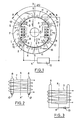
- a single-phase alternator comprising an armature 1 provided with an armature winding 2 connected to the terminals of a load 15 and an inductor 3 which comprises a magnetic circuit 4 having a pair of poles 5 each of which carries two opposite polar horns laterally 6.
- Four excitation windings 7 are formed around the magnetic circuit 4 between the two poles 5, according to an axis substantially parallel to the axis X-X ⁇ of the poles 5.
- the inductor 3 and the armature 1 are movable in rotation relative to each other, while, most often, the inductor 3 is the rotor, and the armature 1 is fixed.
- the aforementioned elements are produced and mounted in a conventional manner.
- the inductor 3 further comprises two correcting windings 8 arranged on either side of the axis X-X ⁇ of the poles 5 and each of which surrounds the magnetic circuit 4 in a plane parallel to the axis X -X ⁇ by passing through a pair of notches 9 each formed in a different pole 5 so as to open in the substantially cylindrical peripheral surface of this pole.
- Each notch 9 determines a neck 10 between one of the pole horns 6 of the corresponding pole 5 and the rest of the magnetic circuit 4.
- Each corrector winding 8 embraces the two necks 10 adjacent to the two notches 9 which it occupies.
- the axis of the correcting windings 8 is substantially perpendicular to the axis X-X ⁇ of the poles 5.
- each corrector winding 8 is connected to the terminals of a diode 12.
- the two correcting windings 8 are mounted in series at the terminals of a diode 13.
- the necessary insulations are provided between the excitation windings 7, the correcting windings 8 and the magnetic circuit 4.
- the field generated by the corrective windings is added to the main field produced by the inductive windings in one of the horns of each pole and is subtracted of the main field in the other horn of each pole.
- This modification of the state of saturation of the polar horns deforms the field lines in the armature, and this in a direction reducing the proportion of harmonic of order 3 in the tension produced by the alternator.
- the first case it noted on the voltage wave delivered at the output a harmonic rate of order 3 of the order of 23% while in the second case, the rate measured was no more than 9 % under identical operating conditions.
- the Applicant has also found that the correcting windings 8 participate in the reduction of iron losses in the magnetic circuit 4 of the inductor 3 and moreover allow better regulation of the output voltage of the alternator as a function of the load.
- This section of notches can be chosen, for example, so that the individual void harmonic rate does not exceed 2%;
- a minimum notch opening ( e ) determined as a function of the diameter of the wires making up the corrector winding and the mechanical strength of the spout 16 formed by this opening;
- a passage section 2a of the main magnetic flux in the pole horns 6 at least equal to 20% of the 2D passage section of this main flux delimited between the two notches 9 of the pole considered 5.
- the correcting windings can each surround only one of the necks such as 10, that is to say that in the bipolar inductor shown there would be four correcting windings, one around each horn, if all the horns were equipped .
- the correcting windings could each pass through two diametrically opposite notches.
Landscapes
- Engineering & Computer Science (AREA)
- Power Engineering (AREA)
- Synchronous Machinery (AREA)
Applications Claiming Priority (2)
| Application Number | Priority Date | Filing Date | Title |
|---|---|---|---|
| FR8603235A FR2595517B1 (fr) | 1986-03-07 | 1986-03-07 | Alternateur a faible taux d'harmoniques |
| FR8603235 | 1986-03-07 |
Publications (2)
| Publication Number | Publication Date |
|---|---|
| EP0241320A1 true EP0241320A1 (de) | 1987-10-14 |
| EP0241320B1 EP0241320B1 (de) | 1991-06-05 |
Family
ID=9332872
Family Applications (1)
| Application Number | Title | Priority Date | Filing Date |
|---|---|---|---|
| EP87400438A Expired - Lifetime EP0241320B1 (de) | 1986-03-07 | 1987-02-27 | Wechselstromgenerator mit geringem harmonischem Verhältnis |
Country Status (7)
| Country | Link |
|---|---|
| US (1) | US4780633A (de) |
| EP (1) | EP0241320B1 (de) |
| JP (1) | JPS62268341A (de) |
| AU (1) | AU592160B2 (de) |
| DE (1) | DE3770509D1 (de) |
| ES (1) | ES2022387B3 (de) |
| FR (1) | FR2595517B1 (de) |
Cited By (1)
| Publication number | Priority date | Publication date | Assignee | Title |
|---|---|---|---|---|
| EP2814146A3 (de) * | 2013-06-12 | 2016-06-29 | Hamilton Sundstrand Corporation | Dauermagnetsynchronmaschinen mit magnetischer Flusssteuerung |
Families Citing this family (2)
| Publication number | Priority date | Publication date | Assignee | Title |
|---|---|---|---|---|
| FR2842361A1 (fr) * | 2002-07-10 | 2004-01-16 | Leroy Somer Moteurs | Alternateur comportant un rotor comprenant des amortisseurs |
| CN105610255A (zh) * | 2016-03-01 | 2016-05-25 | 中车株洲电力机车研究所有限公司 | 一种电励磁同步电机的转子装置及电机 |
Citations (4)
| Publication number | Priority date | Publication date | Assignee | Title |
|---|---|---|---|---|
| FR364374A (fr) * | 1905-03-18 | 1906-08-21 | Oerlikon Maschf | Inducteur pour génératrice synchrone de courants alternatifs à enroulement formant écran |
| FR1513615A (fr) * | 1966-01-21 | 1968-02-16 | Siemens Ag | Inducteur bipolaire pour machines électriques |
| GB2114819A (en) * | 1982-02-16 | 1983-08-24 | Mase Electromeccanica Spa | Single phase alternator |
| US4573003A (en) * | 1983-09-30 | 1986-02-25 | Wisconsin Alumni Research Foundation | AC Machine optimized for converter operation |
Family Cites Families (6)
| Publication number | Priority date | Publication date | Assignee | Title |
|---|---|---|---|---|
| US4097754A (en) * | 1976-10-20 | 1978-06-27 | Tecumseh Products Company | Short pitch alternator |
| JPS53122714A (en) * | 1977-03-31 | 1978-10-26 | Mitsubishi Electric Corp | Self excitation device for synchronous machine |
| SU830615A1 (ru) * | 1979-03-01 | 1981-05-15 | Куйбышевский Политехнический Институтим. B.B.Куйбышева | Машина посто нного тока |
| JPS5646651A (en) * | 1979-09-24 | 1981-04-27 | Yamaha Motor Co Ltd | Brushless self-excited synchronizing generator having salient-type rotor |
| US4454465A (en) * | 1981-04-29 | 1984-06-12 | Teledyne Walterboro, A Division Of Teledyne Industries, Inc. | Electric generator that operates with few ampere-turns in field winding |
| JPS60241755A (ja) * | 1984-05-12 | 1985-11-30 | Yoshiteru Teraue | プラシレス同期発電機 |
-
1986
- 1986-03-07 FR FR8603235A patent/FR2595517B1/fr not_active Expired
-
1987
- 1987-02-27 ES ES87400438T patent/ES2022387B3/es not_active Expired - Lifetime
- 1987-02-27 DE DE8787400438T patent/DE3770509D1/de not_active Expired - Lifetime
- 1987-02-27 EP EP87400438A patent/EP0241320B1/de not_active Expired - Lifetime
- 1987-03-03 US US07/022,622 patent/US4780633A/en not_active Expired - Lifetime
- 1987-03-06 AU AU69799/87A patent/AU592160B2/en not_active Ceased
- 1987-03-06 JP JP62050411A patent/JPS62268341A/ja active Pending
Patent Citations (4)
| Publication number | Priority date | Publication date | Assignee | Title |
|---|---|---|---|---|
| FR364374A (fr) * | 1905-03-18 | 1906-08-21 | Oerlikon Maschf | Inducteur pour génératrice synchrone de courants alternatifs à enroulement formant écran |
| FR1513615A (fr) * | 1966-01-21 | 1968-02-16 | Siemens Ag | Inducteur bipolaire pour machines électriques |
| GB2114819A (en) * | 1982-02-16 | 1983-08-24 | Mase Electromeccanica Spa | Single phase alternator |
| US4573003A (en) * | 1983-09-30 | 1986-02-25 | Wisconsin Alumni Research Foundation | AC Machine optimized for converter operation |
Cited By (1)
| Publication number | Priority date | Publication date | Assignee | Title |
|---|---|---|---|---|
| EP2814146A3 (de) * | 2013-06-12 | 2016-06-29 | Hamilton Sundstrand Corporation | Dauermagnetsynchronmaschinen mit magnetischer Flusssteuerung |
Also Published As
| Publication number | Publication date |
|---|---|
| AU6979987A (en) | 1987-11-12 |
| JPS62268341A (ja) | 1987-11-20 |
| AU592160B2 (en) | 1990-01-04 |
| EP0241320B1 (de) | 1991-06-05 |
| US4780633A (en) | 1988-10-25 |
| ES2022387B3 (es) | 1991-12-01 |
| FR2595517B1 (fr) | 1988-06-24 |
| FR2595517A1 (fr) | 1987-09-11 |
| DE3770509D1 (de) | 1991-07-11 |
Similar Documents
| Publication | Publication Date | Title |
|---|---|---|
| EP0183576B1 (de) | Drehende Maschine mit Permanentmagneten | |
| US6369474B1 (en) | Alternating current generator for vehicle | |
| US20020060505A1 (en) | Generator with diverse power-generation characteristics | |
| US20070210656A1 (en) | Compact high power alternator | |
| FR2769422A1 (fr) | Machine electrique a commutation de flux, et notamment alternateur de vehicule automobile | |
| EP3357151B1 (de) | 12-phasiger transformator-gleichrichter | |
| FR2854990A1 (fr) | Machine electrique rotative | |
| FR3072835A1 (fr) | Machine electrique rotative | |
| EP0241320B1 (de) | Wechselstromgenerator mit geringem harmonischem Verhältnis | |
| FR2664837A1 (fr) | Poste de soudure a moteur perfectionne. | |
| EP0080925A1 (de) | Statischer Gleichrichterumformer mit einer zwei Graetzbrücken enthaltenden zwölfphasigen Schaltung zur Unterdrückung der Oberwellen 5 und 7 im Netzstrom | |
| WO2021116040A1 (fr) | Flasque pour machine électrique tournante | |
| FR2710466A1 (fr) | Rotor de machine synchrone. | |
| CN1109395C (zh) | 两极涡轮发电机及其转子 | |
| EP0828335B1 (de) | Kraftfahrzeuggenerator mit Dreiphasenwicklungen | |
| FR2775393A1 (fr) | Machine dynamo-electrique a reluctance variable hybride a effet vernier a grande plage et vitesse | |
| FR2566975A1 (fr) | Perfectionnements aux machines tournantes electriques, notamment aux generateurs autonomes a plusieurs sorties | |
| FR2767236A1 (fr) | Machine electrique, en particulier machine pour courant triphase | |
| FR2523780A1 (fr) | Generatrice de courant electrique equipee de pales de refroidissement dont la vitesse de rotation ne depasse pas une valeur constante | |
| BE417132A (de) | ||
| JP3428244B2 (ja) | 直流電動機 | |
| FR3150365A1 (fr) | Système de transmission inductif pour transmettre de l’énergie électrique à un enroulement d’excitation de rotor | |
| FR3142864A1 (fr) | Équipement électrique | |
| BE468075A (de) | ||
| BE513016A (de) |
Legal Events
| Date | Code | Title | Description |
|---|---|---|---|
| PUAI | Public reference made under article 153(3) epc to a published international application that has entered the european phase |
Free format text: ORIGINAL CODE: 0009012 |
|
| 17P | Request for examination filed |
Effective date: 19870305 |
|
| AK | Designated contracting states |
Kind code of ref document: A1 Designated state(s): DE ES GB IT |
|
| 17Q | First examination report despatched |
Effective date: 19890505 |
|
| ITF | It: translation for a ep patent filed | ||
| GRAA | (expected) grant |
Free format text: ORIGINAL CODE: 0009210 |
|
| AK | Designated contracting states |
Kind code of ref document: B1 Designated state(s): DE ES GB IT |
|
| GBT | Gb: translation of ep patent filed (gb section 77(6)(a)/1977) | ||
| REF | Corresponds to: |
Ref document number: 3770509 Country of ref document: DE Date of ref document: 19910711 |
|
| PLBE | No opposition filed within time limit |
Free format text: ORIGINAL CODE: 0009261 |
|
| STAA | Information on the status of an ep patent application or granted ep patent |
Free format text: STATUS: NO OPPOSITION FILED WITHIN TIME LIMIT |
|
| 26N | No opposition filed | ||
| REG | Reference to a national code |
Ref country code: GB Ref legal event code: IF02 |
|
| PGFP | Annual fee paid to national office [announced via postgrant information from national office to epo] |
Ref country code: GB Payment date: 20020214 Year of fee payment: 16 |
|
| PGFP | Annual fee paid to national office [announced via postgrant information from national office to epo] |
Ref country code: ES Payment date: 20020228 Year of fee payment: 16 |
|
| PG25 | Lapsed in a contracting state [announced via postgrant information from national office to epo] |
Ref country code: GB Free format text: LAPSE BECAUSE OF NON-PAYMENT OF DUE FEES Effective date: 20030227 |
|
| PG25 | Lapsed in a contracting state [announced via postgrant information from national office to epo] |
Ref country code: ES Free format text: LAPSE BECAUSE OF NON-PAYMENT OF DUE FEES Effective date: 20030228 |
|
| PGFP | Annual fee paid to national office [announced via postgrant information from national office to epo] |
Ref country code: DE Payment date: 20030306 Year of fee payment: 17 |
|
| GBPC | Gb: european patent ceased through non-payment of renewal fee | ||
| REG | Reference to a national code |
Ref country code: ES Ref legal event code: FD2A Effective date: 20030228 |
|
| PG25 | Lapsed in a contracting state [announced via postgrant information from national office to epo] |
Ref country code: DE Free format text: LAPSE BECAUSE OF NON-PAYMENT OF DUE FEES Effective date: 20040901 |
|
| PG25 | Lapsed in a contracting state [announced via postgrant information from national office to epo] |
Ref country code: IT Free format text: LAPSE BECAUSE OF NON-PAYMENT OF DUE FEES Effective date: 20050227 |