EP0241290A1 - Cooling system for electronic components - Google Patents
Cooling system for electronic components Download PDFInfo
- Publication number
- EP0241290A1 EP0241290A1 EP87303101A EP87303101A EP0241290A1 EP 0241290 A1 EP0241290 A1 EP 0241290A1 EP 87303101 A EP87303101 A EP 87303101A EP 87303101 A EP87303101 A EP 87303101A EP 0241290 A1 EP0241290 A1 EP 0241290A1
- Authority
- EP
- European Patent Office
- Prior art keywords
- substrate
- layer
- heat
- plate
- block
- Prior art date
- Legal status (The legal status is an assumption and is not a legal conclusion. Google has not performed a legal analysis and makes no representation as to the accuracy of the status listed.)
- Granted
Links
Images
Classifications
-
- H—ELECTRICITY
- H01—ELECTRIC ELEMENTS
- H01L—SEMICONDUCTOR DEVICES NOT COVERED BY CLASS H10
- H01L23/00—Details of semiconductor or other solid state devices
- H01L23/34—Arrangements for cooling, heating, ventilating or temperature compensation ; Temperature sensing arrangements
- H01L23/46—Arrangements for cooling, heating, ventilating or temperature compensation ; Temperature sensing arrangements involving the transfer of heat by flowing fluids
- H01L23/473—Arrangements for cooling, heating, ventilating or temperature compensation ; Temperature sensing arrangements involving the transfer of heat by flowing fluids by flowing liquids
-
- H—ELECTRICITY
- H01—ELECTRIC ELEMENTS
- H01L—SEMICONDUCTOR DEVICES NOT COVERED BY CLASS H10
- H01L23/00—Details of semiconductor or other solid state devices
- H01L23/34—Arrangements for cooling, heating, ventilating or temperature compensation ; Temperature sensing arrangements
- H01L23/40—Mountings or securing means for detachable cooling or heating arrangements ; fixed by friction, plugs or springs
- H01L23/4006—Mountings or securing means for detachable cooling or heating arrangements ; fixed by friction, plugs or springs with bolts or screws
- H01L2023/4037—Mountings or securing means for detachable cooling or heating arrangements ; fixed by friction, plugs or springs with bolts or screws characterised by thermal path or place of attachment of heatsink
- H01L2023/4062—Mountings or securing means for detachable cooling or heating arrangements ; fixed by friction, plugs or springs with bolts or screws characterised by thermal path or place of attachment of heatsink heatsink to or through board or cabinet
-
- H—ELECTRICITY
- H01—ELECTRIC ELEMENTS
- H01L—SEMICONDUCTOR DEVICES NOT COVERED BY CLASS H10
- H01L2924/00—Indexing scheme for arrangements or methods for connecting or disconnecting semiconductor or solid-state bodies as covered by H01L24/00
- H01L2924/0001—Technical content checked by a classifier
- H01L2924/0002—Not covered by any one of groups H01L24/00, H01L24/00 and H01L2224/00
-
- Y—GENERAL TAGGING OF NEW TECHNOLOGICAL DEVELOPMENTS; GENERAL TAGGING OF CROSS-SECTIONAL TECHNOLOGIES SPANNING OVER SEVERAL SECTIONS OF THE IPC; TECHNICAL SUBJECTS COVERED BY FORMER USPC CROSS-REFERENCE ART COLLECTIONS [XRACs] AND DIGESTS
- Y10—TECHNICAL SUBJECTS COVERED BY FORMER USPC
- Y10T—TECHNICAL SUBJECTS COVERED BY FORMER US CLASSIFICATION
- Y10T29/00—Metal working
- Y10T29/49—Method of mechanical manufacture
- Y10T29/49002—Electrical device making
- Y10T29/49117—Conductor or circuit manufacturing
- Y10T29/49124—On flat or curved insulated base, e.g., printed circuit, etc.
- Y10T29/4913—Assembling to base an electrical component, e.g., capacitor, etc.
- Y10T29/49144—Assembling to base an electrical component, e.g., capacitor, etc. by metal fusion
Definitions
- the present invention relates to a cooling system used for a package mounting a plurality of heat-generating electronic components such as integrated circuits (IC's) on a substrate.
- IC integrated circuits
- a prior art cooling system for a package mounting electronic components on a substrate is disclosed in U.S. Patent No. 4,109,707.
- the system comprises a micropackage 10 mounting a plurality of IC's on the upper surface of a substrate 12, a connector 20 connected to the package 10, and a heat exchanger 26 in contact with the lower surface 24 of the substrate 12 mounting no IC.
- Liquid coolant such as water flows inside the exchanger 26.
- the exchanger 26 is provided with a flexible thin plate 31 on the bottom thereof.
- the surface 24 of the package 10 is not completely flat.
- the system tries to bring the plate 31 in close contact with the surface 24 by deforming the plate 31 with the pressure of water circulating inside exchanger 26.
- the plate 31 provided on the bottom of the exchanger 26 is made of an extremely thin copper sheet having a thickness of 0.05 to 0.25 milimeters in order to obtain superior flexibility.
- the water pressure used to press the plate 31 against the surface 24, which is a determinant factor of the thermal resistance between the plate 31 and the surface 24, cannot be increased to thereby present an impediment in reducing the thermal resistance between the substrate 12 and the exchanger 26.
- the plate 21 must be handled with utmost care when it is removed from the package 10 at the time of replacement. If the plate 21 is damaged, the water inside the exchanger 26 may leak to malfunction the IC's.
- a cooling system which comprises: a substrate mounting electronic components; a first layer made of adhesive provided on one surface of the substrate; a second layer made of a material having a low melting point and provided on the first layer; and a heat-radiating means provided on the second layer to outwardly radiate heat transmitted from the components through the substrate, the first layer and the second layer.
- An object of this invention is to provide a cooling system which is free of aforementioned problems.
- an embodiment of the invention comprises a printed circuit board 1, a connector 2, a wiring substrate 3, adhesive 4, a metal layer 5 made of a material having a low melting point, a radiating conducting block 6, a holder 7, a cold plate 8, through holes 9, threaded holes 10, screws 11 for engaging with the holes 10, an inlet 12 for coolant, an outlet 13 for coolant, IC chips 14, threaded holes 21 and through holes 22.
- the upper surface of the substrate 3 is provided with a plurality of heat-generating components including the IC chips 14.
- the holder 7 is attached to the connector 2 by the screws 20 which penetrate through the holes 22 to engage with the holes 21.
- the layer 5 made of solder or wax material is formed on the lower surface of the block 6.
- the layer 5 is fixed to the lower surface of the substrate 3 by the adhesive 4 obtained by mixing silicone rubber and a filler of high thermal conductivity. In the manner mentioned above, there is formed a module comprising the substrate 3, the adhesive 4, the layer 5 and the block 6.
- no gap or clearance between the substrate 3 and the block 6 is caused by deformations such as warps on the substrate 3 or the block 6 which are often seen in the above-mentioned prior art structure. Since the flexible adhesive 4 is used, there will be no gaps or clearances between the substrate 3 and the block 6 due to such a difference even if the thermal expansion coefficient of the substrate 3 may differ from that of the block 6.
- the block 6 is snugly fixed to the cold plate 8 inside which liquid coolant is circulated.
- the opposed surfaces of the block 6 and the plate 8 are finished to give a particularly high flatness.
- the heat generated from the IC chips 14 is conducted through the substrate 3, the adhesive 4 and the layer 5 to the block 6.
- the thermal resistance of the path can be kept low. Further, because the block 6 and the plate 8 are closely pressed to each other with a high pressure applied by the screw 11, the thermal resistance therebetween can also be kept low. The heat generated from the IC chips 14 reaches the cold plate 8 to be carried away outside by the coolant circulating through the plate 8. As is described above, unlike the prior art structure the embodiment does not use any flexible thin sheets to enhance mechanical strength and avoid possibility of any water leakage which may be caused by careless handling.
- the block 6 When the block 6 is to be removed from the substrate 3 at the time of replacement of defective one or ones of the IC chips 14, it would be extremely difficult to separate one from the other if they are adhered to each other with the adhesives 4 alone.
- the embodiment uses the layer 5, they are easily separated simply by melting the layer, and the adhesive 4 can be easily removed from the substrate 3 after the separation.
- the layer 5 is formed again on the lower surface of the block 6 and the block 6 is then ready to be adhered to the substrate 3 with the adhesive 4.
- a heat sink for air cooling may be used in place of the plate 8.
Abstract
Description
- The present invention relates to a cooling system used for a package mounting a plurality of heat-generating electronic components such as integrated circuits (IC's) on a substrate.
- A prior art cooling system for a package mounting electronic components on a substrate is disclosed in U.S. Patent No. 4,109,707. The system comprises a
micropackage 10 mounting a plurality of IC's on the upper surface of asubstrate 12, aconnector 20 connected to thepackage 10, and a heat exchanger 26 in contact with the lower surface 24 of thesubstrate 12 mounting no IC. Liquid coolant such as water flows inside the exchanger 26. The exchanger 26 is provided with a flexible thin plate 31 on the bottom thereof. The surface 24 of thepackage 10 is not completely flat. In order to efficiently conduct the heat generated from the IC's into the coolant, it is critically necessary to force the flexible plate 31 to come into close contact with the surface 24 without clearances therebetween. To obtain such close contact, the system tries to bring the plate 31 in close contact with the surface 24 by deforming the plate 31 with the pressure of water circulating inside exchanger 26. - In the system, the plate 31 provided on the bottom of the exchanger 26 is made of an extremely thin copper sheet having a thickness of 0.05 to 0.25 milimeters in order to obtain superior flexibility. However, since it is made of such a thin sheet of material, the water pressure used to press the plate 31 against the surface 24, which is a determinant factor of the thermal resistance between the plate 31 and the surface 24, cannot be increased to thereby present an impediment in reducing the thermal resistance between the
substrate 12 and the exchanger 26. Because of its weakness, theplate 21 must be handled with utmost care when it is removed from thepackage 10 at the time of replacement. If theplate 21 is damaged, the water inside the exchanger 26 may leak to malfunction the IC's. - According to an aspect of the invention, there is provided a cooling system which comprises: a substrate mounting electronic components; a first layer made of adhesive provided on one surface of the substrate; a second layer made of a material having a low melting point and provided on the first layer; and a heat-radiating means provided on the second layer to outwardly radiate heat transmitted from the components through the substrate, the first layer and the second layer.
- An object of this invention is to provide a cooling system which is free of aforementioned problems.
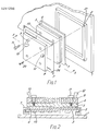
- FIG. 1 is a perspective view of an embodiment of the invention; and
- FIG. 2 is a cross-sectional view of the embodiment.
- In the figures, the same reference numerals represent the same structural elements.
- Referring to FIGs. 1 and 2, an embodiment of the invention comprises a printed circuit board 1, a
connector 2, awiring substrate 3, adhesive 4, ametal layer 5 made of a material having a low melting point, a radiating conducting block 6, a holder 7, acold plate 8, throughholes 9, threadedholes 10,screws 11 for engaging with theholes 10, aninlet 12 for coolant, anoutlet 13 for coolant,IC chips 14, threadedholes 21 and throughholes 22. - In the drawings, the upper surface of the
substrate 3 is provided with a plurality of heat-generating components including theIC chips 14. The holder 7 is attached to theconnector 2 by thescrews 20 which penetrate through theholes 22 to engage with theholes 21. As a result, thesubstrate 3 is forced against theconnector 2 with the holder 7 to electrically connect theIC chips 14 with wiring patterns in the board 1. Thelayer 5 made of solder or wax material is formed on the lower surface of the block 6. Thelayer 5 is fixed to the lower surface of thesubstrate 3 by theadhesive 4 obtained by mixing silicone rubber and a filler of high thermal conductivity. In the manner mentioned above, there is formed a module comprising thesubstrate 3, theadhesive 4, thelayer 5 and the block 6. In the embodiment, no gap or clearance between thesubstrate 3 and the block 6 is caused by deformations such as warps on thesubstrate 3 or the block 6 which are often seen in the above-mentioned prior art structure. Since theflexible adhesive 4 is used, there will be no gaps or clearances between thesubstrate 3 and the block 6 due to such a difference even if the thermal expansion coefficient of thesubstrate 3 may differ from that of the block 6. The block 6 is snugly fixed to thecold plate 8 inside which liquid coolant is circulated. The opposed surfaces of the block 6 and theplate 8 are finished to give a particularly high flatness. The heat generated from theIC chips 14 is conducted through thesubstrate 3, theadhesive 4 and thelayer 5 to the block 6. Since there is no gap or clearance on the heat conductive path, the thermal resistance of the path can be kept low. Further, because the block 6 and theplate 8 are closely pressed to each other with a high pressure applied by thescrew 11, the thermal resistance therebetween can also be kept low. The heat generated from theIC chips 14 reaches thecold plate 8 to be carried away outside by the coolant circulating through theplate 8. As is described above, unlike the prior art structure the embodiment does not use any flexible thin sheets to enhance mechanical strength and avoid possibility of any water leakage which may be caused by careless handling. - When the block 6 is to be removed from the
substrate 3 at the time of replacement of defective one or ones of theIC chips 14, it would be extremely difficult to separate one from the other if they are adhered to each other with theadhesives 4 alone. However, since the embodiment uses thelayer 5, they are easily separated simply by melting the layer, and theadhesive 4 can be easily removed from thesubstrate 3 after the separation. When re-assembling them, thelayer 5 is formed again on the lower surface of the block 6 and the block 6 is then ready to be adhered to thesubstrate 3 with theadhesive 4. - Although the
plate 8 through which the coolant is circulated is used in the embodiment, a heat sink for air cooling may be used in place of theplate 8.
Claims (3)
Applications Claiming Priority (2)
| Application Number | Priority Date | Filing Date | Title |
|---|---|---|---|
| JP61082724A JPS62238653A (en) | 1986-04-09 | 1986-04-09 | Cooling structure |
| JP82724/86 | 1986-04-09 |
Publications (2)
| Publication Number | Publication Date |
|---|---|
| EP0241290A1 true EP0241290A1 (en) | 1987-10-14 |
| EP0241290B1 EP0241290B1 (en) | 1990-07-04 |
Family
ID=13782360
Family Applications (1)
| Application Number | Title | Priority Date | Filing Date |
|---|---|---|---|
| EP87303101A Expired - Lifetime EP0241290B1 (en) | 1986-04-09 | 1987-04-09 | Cooling system for electronic components |
Country Status (4)
| Country | Link |
|---|---|
| US (1) | US4794981A (en) |
| EP (1) | EP0241290B1 (en) |
| JP (1) | JPS62238653A (en) |
| DE (1) | DE3763504D1 (en) |
Cited By (4)
| Publication number | Priority date | Publication date | Assignee | Title |
|---|---|---|---|---|
| GB2242069A (en) * | 1990-03-08 | 1991-09-18 | Nobuo Mikoshiba | Arrangement for cooling a semiconductor element |
| DE4210835C1 (en) * | 1992-04-01 | 1993-06-17 | Siemens Nixdorf Informationssysteme Ag, 4790 Paderborn, De | |
| EP1328143A1 (en) * | 2002-01-10 | 2003-07-16 | Wen-Chen Wei | Flexible heat pipe |
| WO2008008085A2 (en) * | 2005-09-30 | 2008-01-17 | Intel Corporation | Ic coolant microchannel assembly with integrated attachment hardware |
Families Citing this family (23)
| Publication number | Priority date | Publication date | Assignee | Title |
|---|---|---|---|---|
| US4942497A (en) * | 1987-07-24 | 1990-07-17 | Nec Corporation | Cooling structure for heat generating electronic components mounted on a substrate |
| CA1283225C (en) * | 1987-11-09 | 1991-04-16 | Shinji Mine | Cooling system for three-dimensional ic package |
| EP0320198B1 (en) * | 1987-12-07 | 1995-03-01 | Nec Corporation | Cooling system for IC package |
| DE68918156T2 (en) * | 1988-05-09 | 1995-01-12 | Nec Corp | Flat cooling structure for integrated circuit. |
| US4975766A (en) * | 1988-08-26 | 1990-12-04 | Nec Corporation | Structure for temperature detection in a package |
| JPH06100408B2 (en) * | 1988-09-09 | 1994-12-12 | 日本電気株式会社 | Cooling system |
| CA1304830C (en) * | 1988-09-20 | 1992-07-07 | Toshifumi Sano | Cooling structure |
| US4938280A (en) * | 1988-11-07 | 1990-07-03 | Clark William E | Liquid-cooled, flat plate heat exchanger |
| US5146981A (en) * | 1991-11-14 | 1992-09-15 | Digital Equipment Corporation | Substrate to heatsink interface apparatus and method |
| JP3067399B2 (en) * | 1992-07-03 | 2000-07-17 | 株式会社日立製作所 | Semiconductor cooling device |
| US5359768A (en) * | 1992-07-30 | 1994-11-01 | Intel Corporation | Method for mounting very small integrated circuit package on PCB |
| US5550326A (en) * | 1994-07-13 | 1996-08-27 | Parker-Hannifin Corporation | Heat dissipator for electronic components |
| KR100245971B1 (en) * | 1995-11-30 | 2000-03-02 | 포만 제프리 엘 | Heat sink assembly using adhesion promoting layer for bonding polymeric adhesive to metal and the method of making the same |
| US6173760B1 (en) * | 1998-08-04 | 2001-01-16 | International Business Machines Corporation | Co-axial bellows liquid heatsink for high power module test |
| JP2941801B1 (en) * | 1998-09-17 | 1999-08-30 | 北川工業株式会社 | Thermal conductive material |
| DE60215618T2 (en) | 2001-02-28 | 2007-08-30 | Porter Instrument Co., Inc. | ATOMIZERS |
| EP1298168A4 (en) * | 2001-03-28 | 2004-06-23 | Japan Polyolefins Co Ltd | Adhesive resin composition and multilayer structure made with the same |
| US20060263570A1 (en) * | 2005-05-19 | 2006-11-23 | Bunyan Michael H | Thermal lamination module |
| US7849914B2 (en) * | 2006-05-02 | 2010-12-14 | Clockspeed, Inc. | Cooling apparatus for microelectronic devices |
| JP4697475B2 (en) * | 2007-05-21 | 2011-06-08 | トヨタ自動車株式会社 | Power module cooler and power module |
| JP6008582B2 (en) * | 2012-05-28 | 2016-10-19 | 新光電気工業株式会社 | Semiconductor package, heat sink and manufacturing method thereof |
| US11006548B2 (en) * | 2013-02-01 | 2021-05-11 | Smart Embedded Computing, Inc. | Method and device to provide uniform cooling in rugged environments |
| CN109059225A (en) * | 2015-08-17 | 2018-12-21 | 吴彬 | Using the intelligent temperature control system of the smart home system of mobile network communication |
Citations (3)
| Publication number | Priority date | Publication date | Assignee | Title |
|---|---|---|---|---|
| US4237086A (en) * | 1979-02-22 | 1980-12-02 | Rockwell International Corporation | Method for releasably mounting a substrate on a base providing heat transfer and electrical conduction |
| EP0053967A1 (en) * | 1980-12-05 | 1982-06-16 | COMPAGNIE INTERNATIONALE POUR L'INFORMATIQUE CII - HONEYWELL BULL (dite CII-HB) | Removable cooling device for an integrated-circuit mounting |
| EP0167033A2 (en) * | 1984-06-29 | 1986-01-08 | International Business Machines Corporation | Apparatus for conduction cooling |
Family Cites Families (10)
| Publication number | Priority date | Publication date | Assignee | Title |
|---|---|---|---|---|
| US4072188A (en) * | 1975-07-02 | 1978-02-07 | Honeywell Information Systems Inc. | Fluid cooling systems for electronic systems |
| US4282924A (en) * | 1979-03-16 | 1981-08-11 | Varian Associates, Inc. | Apparatus for mechanically clamping semiconductor wafer against pliable thermally conductive surface |
| US4489570A (en) * | 1982-12-01 | 1984-12-25 | The Board Of Trustees Of The Leland Stanford Junior University | Fast cooldown miniature refrigerators |
| US4602678A (en) * | 1983-09-02 | 1986-07-29 | The Bergquist Company | Interfacing of heat sinks with electrical devices, and the like |
| JPH0673364B2 (en) * | 1983-10-28 | 1994-09-14 | 株式会社日立製作所 | Integrated circuit chip cooler |
| US4546410A (en) * | 1983-10-31 | 1985-10-08 | Kaufman Lance R | Circuit package with membrane, containing thermoconductive material, ruptured against a heat sink |
| US4574879A (en) * | 1984-02-29 | 1986-03-11 | The Bergquist Company | Mounting pad for solid-state devices |
| US4666545A (en) * | 1984-06-27 | 1987-05-19 | The Bergquist Company | Method of making a mounting base pad for semiconductor devices |
| JPH06101523B2 (en) * | 1985-03-04 | 1994-12-12 | 株式会社日立製作所 | Integrated circuit chip cooling device |
| US4602125A (en) * | 1985-05-10 | 1986-07-22 | The Bergquist Company | Mounting pad with tubular projections for solid-state devices |
-
1986
- 1986-04-09 JP JP61082724A patent/JPS62238653A/en active Pending
-
1987
- 1987-04-09 DE DE8787303101T patent/DE3763504D1/en not_active Expired - Fee Related
- 1987-04-09 US US07/036,437 patent/US4794981A/en not_active Expired - Fee Related
- 1987-04-09 EP EP87303101A patent/EP0241290B1/en not_active Expired - Lifetime
Patent Citations (3)
| Publication number | Priority date | Publication date | Assignee | Title |
|---|---|---|---|---|
| US4237086A (en) * | 1979-02-22 | 1980-12-02 | Rockwell International Corporation | Method for releasably mounting a substrate on a base providing heat transfer and electrical conduction |
| EP0053967A1 (en) * | 1980-12-05 | 1982-06-16 | COMPAGNIE INTERNATIONALE POUR L'INFORMATIQUE CII - HONEYWELL BULL (dite CII-HB) | Removable cooling device for an integrated-circuit mounting |
| EP0167033A2 (en) * | 1984-06-29 | 1986-01-08 | International Business Machines Corporation | Apparatus for conduction cooling |
Cited By (7)
| Publication number | Priority date | Publication date | Assignee | Title |
|---|---|---|---|---|
| GB2242069A (en) * | 1990-03-08 | 1991-09-18 | Nobuo Mikoshiba | Arrangement for cooling a semiconductor element |
| US5262673A (en) * | 1990-03-08 | 1993-11-16 | Nobuo Mikoshiba | Semiconductor element |
| GB2242069B (en) * | 1990-03-08 | 1994-02-23 | Nobuo Mikoshiba | Semiconductor element |
| DE4210835C1 (en) * | 1992-04-01 | 1993-06-17 | Siemens Nixdorf Informationssysteme Ag, 4790 Paderborn, De | |
| EP1328143A1 (en) * | 2002-01-10 | 2003-07-16 | Wen-Chen Wei | Flexible heat pipe |
| WO2008008085A2 (en) * | 2005-09-30 | 2008-01-17 | Intel Corporation | Ic coolant microchannel assembly with integrated attachment hardware |
| WO2008008085A3 (en) * | 2005-09-30 | 2008-04-17 | Intel Corp | Ic coolant microchannel assembly with integrated attachment hardware |
Also Published As
| Publication number | Publication date |
|---|---|
| JPS62238653A (en) | 1987-10-19 |
| EP0241290B1 (en) | 1990-07-04 |
| DE3763504D1 (en) | 1990-08-09 |
| US4794981A (en) | 1989-01-03 |
Similar Documents
| Publication | Publication Date | Title |
|---|---|---|
| EP0241290B1 (en) | Cooling system for electronic components | |
| US4509096A (en) | Chip-carrier substrates | |
| US4854377A (en) | Liquid cooling system for integrated circuit chips | |
| US7595991B2 (en) | Using the wave soldering process to attach motherboard chipset heat sinks | |
| US5619399A (en) | Multiple chip module mounting assembly and computer using same | |
| US6219243B1 (en) | Heat spreader structures for enhanced heat removal from both sides of chip-on-flex packaged units | |
| US11497143B2 (en) | Mechanically flexible cold plates for low power components | |
| US5065280A (en) | Flex interconnect module | |
| EP0836227A2 (en) | Heat conductive substrate mounted in PC board hole for transferring heat from IC to heat sink | |
| JP3281220B2 (en) | Circuit module cooling system | |
| JPH07142657A (en) | Semiconductor chip cooler and cooling method | |
| EP0236065B1 (en) | Liquid cooling system for integrated circuit chips | |
| JPH02305498A (en) | Cold plate assembly | |
| WO1996025839A1 (en) | Multiple chip module mounting assembly and computer using same | |
| JPH11330750A (en) | Method for forming heat transfer path and heat transfer path device | |
| US6101094A (en) | Printed circuit board with integrated cooling mechanism | |
| US20180098414A1 (en) | Heat sink assemblies for surface mounted devices | |
| US6921973B2 (en) | Electronic module having compliant spacer | |
| GB2135525A (en) | Heat-dissipating chip carrier substrates | |
| JPH0773159B2 (en) | Circuit card assembly conduction heat exchanger and circuit card assembly cooling method | |
| US6704197B2 (en) | Electronic unit having desired heat radiation properties | |
| CN111954428B (en) | Heat radiation structure and electronic component with same | |
| JPS62118552A (en) | Cooling structure of integrated circuit | |
| JPH0461505B2 (en) | ||
| JPH0461504B2 (en) |
Legal Events
| Date | Code | Title | Description |
|---|---|---|---|
| PUAI | Public reference made under article 153(3) epc to a published international application that has entered the european phase |
Free format text: ORIGINAL CODE: 0009012 |
|
| 17P | Request for examination filed |
Effective date: 19870415 |
|
| AK | Designated contracting states |
Kind code of ref document: A1 Designated state(s): DE FR GB |
|
| 17Q | First examination report despatched |
Effective date: 19890721 |
|
| GRAA | (expected) grant |
Free format text: ORIGINAL CODE: 0009210 |
|
| AK | Designated contracting states |
Kind code of ref document: B1 Designated state(s): DE FR GB |
|
| REF | Corresponds to: |
Ref document number: 3763504 Country of ref document: DE Date of ref document: 19900809 |
|
| ET | Fr: translation filed | ||
| PLBE | No opposition filed within time limit |
Free format text: ORIGINAL CODE: 0009261 |
|
| STAA | Information on the status of an ep patent application or granted ep patent |
Free format text: STATUS: NO OPPOSITION FILED WITHIN TIME LIMIT |
|
| 26N | No opposition filed | ||
| PGFP | Annual fee paid to national office [announced via postgrant information from national office to epo] |
Ref country code: GB Payment date: 19990408 Year of fee payment: 13 |
|
| PGFP | Annual fee paid to national office [announced via postgrant information from national office to epo] |
Ref country code: FR Payment date: 19990409 Year of fee payment: 13 |
|
| PGFP | Annual fee paid to national office [announced via postgrant information from national office to epo] |
Ref country code: DE Payment date: 19990419 Year of fee payment: 13 |
|
| PG25 | Lapsed in a contracting state [announced via postgrant information from national office to epo] |
Ref country code: GB Free format text: LAPSE BECAUSE OF NON-PAYMENT OF DUE FEES Effective date: 20000409 |
|
| GBPC | Gb: european patent ceased through non-payment of renewal fee |
Effective date: 20000409 |
|
| PG25 | Lapsed in a contracting state [announced via postgrant information from national office to epo] |
Ref country code: FR Free format text: LAPSE BECAUSE OF NON-PAYMENT OF DUE FEES Effective date: 20001229 |
|
| PG25 | Lapsed in a contracting state [announced via postgrant information from national office to epo] |
Ref country code: DE Free format text: LAPSE BECAUSE OF NON-PAYMENT OF DUE FEES Effective date: 20010201 |
|
| REG | Reference to a national code |
Ref country code: FR Ref legal event code: ST |