EP0240941B1 - A steering device for paved surface cleaners - Google Patents
A steering device for paved surface cleaners Download PDFInfo
- Publication number
- EP0240941B1 EP0240941B1 EP87104904A EP87104904A EP0240941B1 EP 0240941 B1 EP0240941 B1 EP 0240941B1 EP 87104904 A EP87104904 A EP 87104904A EP 87104904 A EP87104904 A EP 87104904A EP 0240941 B1 EP0240941 B1 EP 0240941B1
- Authority
- EP
- European Patent Office
- Prior art keywords
- handle levers
- controls
- brakes
- electric motor
- electric contact
- Prior art date
- Legal status (The legal status is an assumption and is not a legal conclusion. Google has not performed a legal analysis and makes no representation as to the accuracy of the status listed.)
- Expired - Lifetime
Links
- 230000010355 oscillation Effects 0.000 claims abstract description 6
- XLYOFNOQVPJJNP-UHFFFAOYSA-N water Substances O XLYOFNOQVPJJNP-UHFFFAOYSA-N 0.000 description 11
- 238000005406 washing Methods 0.000 description 5
- 238000005452 bending Methods 0.000 description 2
- 238000010276 construction Methods 0.000 description 2
- 238000012937 correction Methods 0.000 description 2
- 240000007643 Phytolacca americana Species 0.000 description 1
- 230000004075 alteration Effects 0.000 description 1
- 230000000981 bystander Effects 0.000 description 1
- 238000004140 cleaning Methods 0.000 description 1
- 230000000994 depressogenic effect Effects 0.000 description 1
- 238000001035 drying Methods 0.000 description 1
- 238000009408 flooring Methods 0.000 description 1
- 231100001261 hazardous Toxicity 0.000 description 1
- 230000001788 irregular Effects 0.000 description 1
- 238000004519 manufacturing process Methods 0.000 description 1
Images
Classifications
-
- A—HUMAN NECESSITIES
- A47—FURNITURE; DOMESTIC ARTICLES OR APPLIANCES; COFFEE MILLS; SPICE MILLS; SUCTION CLEANERS IN GENERAL
- A47L—DOMESTIC WASHING OR CLEANING; SUCTION CLEANERS IN GENERAL
- A47L11/00—Machines for cleaning floors, carpets, furniture, walls, or wall coverings
- A47L11/40—Parts or details of machines not provided for in groups A47L11/02 - A47L11/38, or not restricted to one of these groups, e.g. handles, arrangements of switches, skirts, buffers, levers
- A47L11/4061—Steering means; Means for avoiding obstacles; Details related to the place where the driver is accommodated
Definitions
- This invention relates to a steering device for paved surface cleaners of the self-propelled variety with no fixed steering or driver's station.
- the machines in question Being intended for cleaning large surfaces and to be a work implement proper, the machines in question are made self-propelled and equipped with a specific steering device.
- the steering device moreover, is to provide highly responsive and effective steering control, because such machines are also to be driven along twisting and irregular paths.
- Each handle lever is positioned close to a fixed grip standing proud of the machine at a location from where the machine movements can be conveniently hand controlled.
- the operator can leave the handle levers, if necessary, and presently seize said grips in the event that movements by hand become unavoidable.
- Rotation of each articulated portion is to be effected toward the other lever, or inwards of the machine outline, to avoid hazardous protrusion while manoeuvering.
- the operator walking behind such a machine turns the articulated portion of the left-hand lever rightwards, from his standpoint, to tension a wire cable braking a left-hand driving wheel, or turns the articulated portion of the right-hand lever leftwards to tension a wire cable braking a right-hand driving wheel.
- That steering device while being suitable for steering said machine types, still has drawbacks.
- a further object of this invention is to provide a device which can be retrofitted to machine as specified above which incorporate the steering system described above, in lieu thereof.
- a steering device for paved surface cleaners of a type comprising at least one first forward travel control assembly having two handle levers for manual oscillation thereof in an angular direction, an electric motor controlled by oscillation of said handle levers, and two traction wheels driven by said electric motor, and a second control assembly of the steering action acting selectively on brakes of said traction wheels, characterized in that said second control assembly is independent of movements of said handle levers and includes electric contact controls located on said handle levers and being operable manually to apply said brakes.
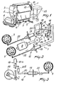
- Figure 1 is a perspective view of a cleaner machine incorporating the steering device of this invention
- Figures 2 and 3 show the construction of the inventive steering device.
- the device of this invention is indicated at 1. It is intended for steering control of a paved surface cleaner of the type referred to as "auto-scrubber" and indicated at 2 in Figure 1.
- This machine 2 comprises, in a manner known per se, a case 3 substantially in the form of a compact block accommodating therein a first reservoir for clean washing water, a second reservoir for foul regain water, clean water delivery members and foul water suction members.
- a brush assembly 4 accommodating brushes which are constantly wet with washing water and rotatable by motors overlying the brushes.
- Rearwardly of the case 3 there is a floor wiping blade 5 lying across the forward travel direction and being connected to the cited foul water suction members.
- Downwardly of the case 3 there are two front driving or traction wheels 6 and two rear casters 7.
- the traction wheels 6 are carried on two axles extending out of a differential gear.
- the two traction wheels 6 are driven rotatively by an electric motor 8 (Fig. 2) suitably coupled to a reduction gear included to the differential gearcase.
- Each traction wheel 6 is provided with a respective drum brake 9 (Fig.s 2 and 3).
- the steering device 1 is located in the top rear area of the case 3 wherefrom there stand up two rigidly attached grips 10 set apart and located close to the corner edges of the case 3 (Fig.1).
- the device 1 of this invention includes a first control assembly 11 for controlling the machine forward movement, and a second control assembly 12 for steering the machine 2.
- the first assembly 11 is expediently provided with handle levers 13 oscillating in an angular direction around a hinge bar extending through two holes 14 formed in bases 15 of the handle levers.
- the levers comprise handgrips 16 located in close proximity to the grips 10 (Fig.1) and being a continuation of the bases 14.
- the handgrips 16 are supported rigidly, without any intermediate articulation, on the bases 15. Furthermore, the bases 15 of the two handle levers are interconnected rigidly by a plate 17. The levers 13 are therefore oscillable synchronously around the cited hinge bar.
- Rotation of the hinge bar, and hence of the handle levers 13, will conventionally control the electric motor 8 and hence the machine 2 speed and forward or reverse direction movement.
- the second assembly 12 it becomes instead possible to selectively apply the brakes 9 of each traction wheel 6 of the machine 1 to steer the same to a greater or lesser extent.
- the second assembly 12 peculiarly comprises electric contact controls 18 having pushbutton controls 21a suitably arranged on the top ends of either levers 13, whereby an operator seizing the handgrips 16 can easily depress the pushbutton controls 21a.
- the latter are connected to two electromagnets 19.
- the electromagnets 19 are connected at one end to the pushbutton controls 21a by electric cables 20 and auxiliary pushbuttons 21b, and at the other end to rigid tie rods 22. These are connected to the brakes 9 and control application of same on the electromagnets tensioning the rods 22.
- Depression of the pushbutton controls 21a will activate in parallel both the electromagnets 19 and means of variably absorbing the current intensity to the electric motor 8 comprising a rheostat 23.
- Said rheostat is connected to both pushbutton controls 21a, located in an electric power supply line 24 to the motor 8, and so constructed as to make an increased action of an electromagnet 19 on a brake 9 to result in an increased resistance to the flow of current through the line 24.
- the inventive steering device operates as follows.
- the handle levers 13 are made rigid together to control forward and reverse travel of the machine 2; on rotating either lever 13 toward or away froim the case 3 of the machine 2 both levers are rotated to provide straight line forward or reverse movement of the machine 2.
- the efficiency of the steering device provided is enhanced, which has simple and naturally operable controls in all circumstances, requires no broad movements, comprises members which ensure prompt and effective actuation of the operator's controls, and offers technical solutions which facilitate, by the aforesaid slowing down, control of the machine where the control operations become most involved.
- the device 1 Owing to its simplicity the device 1 is of low cost and may be readily retrofitted to existing machines, since its members can be easily accommodated within the machines without any structural alterations. Thus, it becomes possible to improve safety and operability of currently sold "auto-scrubbers" as well.
Landscapes
- Vehicle Cleaning, Maintenance, Repair, Refitting, And Outriggers (AREA)
- Road Paving Machines (AREA)
- Handcart (AREA)
- Road Repair (AREA)
- Cleaning In General (AREA)
- Finish Polishing, Edge Sharpening, And Grinding By Specific Grinding Devices (AREA)
- Cleaning By Liquid Or Steam (AREA)
Abstract
Description
- This invention relates to a steering device for paved surface cleaners of the self-propelled variety with no fixed steering or driver's station.
- As is known, there are available on the market, and currently manufactured by the Applicant, machines for washing clean and drying the floors of warehouses, sheds, commercial establishments, and more generally, large surface area floorings. Such machines are commonly referred to as auto-scrubbers.
- These are machines relatively compact in size which can poke into the narrowest corners of a storehouse, for example. They include a frame supporting a reservoir of clean washing water, a reservoir for foul regain water, clean water delivery members and foul water suction members, rotary brushes which are constantly wet with washing water, drive motors for said brushes, and at least one floor-wiping blade lying across the machine direction of travel and set rearwards of the brushes.
- Being intended for cleaning large surfaces and to be a work implement proper, the machines in question are made self-propelled and equipped with a specific steering device. The steering device, moreover, is to provide highly responsive and effective steering control, because such machines are also to be driven along twisting and irregular paths.
- However, such machines, or at least the most compact among them, owing to their small overall size, lack any fixed driver's compartment or steering station for the operator including a rest seat. The operator is to control the machine in a standing posture while walking behind it.
- In view of the foregoing, it will be appreciated that the machine cannot be operated by means of pedal controls on a substantially continuous basis, since the operator's feet would be distracted therefrom.
- Nor does the use of ordinary steering wheels appears to be appropriate or convenient, given that these devices only afford prompt control of the steering action proper and no forward and reverse running control, both hands of the operator being kept busy handling it.
- It should be also considered that, with such relatively compact size machines for steering by a walking operator, it is not unusual for some movements to involve the operator's brawn, in order to impart rough travel path corrections. Steering wheels compel the operator to keep his hands close together in one machine area from where shifting by force and purely manual position corrections are difficult to apply.
- Accordingly, it is common practice to provide, for controlling such machines, steering devices based upon the use of two handle levers set well apart on the rear side of the machine, in front of the walking operator behind it.
- Each handle lever is positioned close to a fixed grip standing proud of the machine at a location from where the machine movements can be conveniently hand controlled.
- In this case, the operator can leave the handle levers, if necessary, and presently seize said grips in the event that movements by hand become unavoidable.
- The provision of two separate handle levers also enables actuation of a number of controls by hand only.
- For these reasons, the Applicant has been manufacturing such type machines as are equipped with steering devices based on operation of two discrete handle levers.
- There exists, however, with said handle levers the engineering problem of combining and arranging the various controls, both at the level of the handle levers and downstream thereof, for them to be simple and effective, and accordingly, easy to use and responsive and reliable in their actions.
- It should be noted that the machines in question are sometimes operated by relatively unskilled personnel, and that it is therefore important, from the standpoint of safety as well, that the controls be kept simple and efficient.
- The state of the art provides for shifting the handle levers toward the machine body to control forward travel, whereas shifting them away from the machine body controls reverse direction travel. Also, either lever has an articulated portion facing up in the inoperative position, on bending which parallel with the machine body, selective braking of the driving wheels is controlled via appropriate wire cables to drive the machine along a bending path.
- Rotation of each articulated portion is to be effected toward the other lever, or inwards of the machine outline, to avoid hazardous protrusion while manoeuvering.
- In other words, the operator walking behind such a machine turns the articulated portion of the left-hand lever rightwards, from his standpoint, to tension a wire cable braking a left-hand driving wheel, or turns the articulated portion of the right-hand lever leftwards to tension a wire cable braking a right-hand driving wheel. These manoeuvers respectively result in the machine turning to the left and the right.
- That steering device, while being suitable for steering said machine types, still has drawbacks.
- In fact, the movements that an operator is to perform in order to drive along a non-linear path are hardly natural ones and; above all, are far-reaching and tiring ones; the articulated portions of the handle levers must be constantly bent to selectively brake the driving wheels. Furthermore, relatively complex and easily inaccurate movements are required to both steer and speed up or slow down. The operator's fatigue due to such extensive and continued movements, and the likely inaccuracy of same on the occasion of complicated manoeuvers, may be a potential hazard for bystanders as well as for objects lying close to the cleaner path of movement.
- This being the situation, the technical problem underlying this invention is to provide a steering device for cleaner machines as indicated which can substantially obviate the above-mentioned drawbacks.
- Within the above technical aim, it is an important object of this invention to provide a device of simple construction, reliable in operation, and requiring no effort by an operator in any of its operating situations.
- A further object of this invention is to provide a device which can be retrofitted to machine as specified above which incorporate the steering system described above, in lieu thereof.
- The outlined technical aim and the objects specified hereinabove are substantially achieved by a steering device for paved surface cleaners, of a type comprising at least one first forward travel control assembly having two handle levers for manual oscillation thereof in an angular direction, an electric motor controlled by oscillation of said handle levers, and two traction wheels driven by said electric motor, and a second control assembly of the steering action acting selectively on brakes of said traction wheels, characterized in that said second control assembly is independent of movements of said handle levers and includes electric contact controls located on said handle levers and being operable manually to apply said brakes.
- Further features will become apparent from the description of a steering device as shown in the accompanying drawings, where:
Figure 1 is a perspective view of a cleaner machine incorporating the steering device of this invention; and
Figures 2 and 3 show the construction of the inventive steering device. - With reference to the drawing figures, the device of this invention is indicated at 1. It is intended for steering control of a paved surface cleaner of the type referred to as "auto-scrubber" and indicated at 2 in Figure 1.
- This
machine 2 comprises, in a manner known per se, acase 3 substantially in the form of a compact block accommodating therein a first reservoir for clean washing water, a second reservoir for foul regain water, clean water delivery members and foul water suction members. Forwardly of thecase 3 there is abrush assembly 4 accommodating brushes which are constantly wet with washing water and rotatable by motors overlying the brushes. Rearwardly of thecase 3 there is afloor wiping blade 5 lying across the forward travel direction and being connected to the cited foul water suction members. Downwardly of thecase 3 there are two front driving or traction wheels 6 and tworear casters 7. The traction wheels 6 are carried on two axles extending out of a differential gear. The two traction wheels 6 are driven rotatively by an electric motor 8 (Fig. 2) suitably coupled to a reduction gear included to the differential gearcase. Each traction wheel 6 is provided with a respective drum brake 9 (Fig.s 2 and 3). - The steering device 1 is located in the top rear area of the
case 3 wherefrom there stand up two rigidly attachedgrips 10 set apart and located close to the corner edges of the case 3 (Fig.1). - The device 1 of this invention includes a
first control assembly 11 for controlling the machine forward movement, and asecond control assembly 12 for steering themachine 2. - The
first assembly 11 is expediently provided with handle levers 13 oscillating in an angular direction around a hinge bar extending through twoholes 14 formed inbases 15 of the handle levers. The levers comprisehandgrips 16 located in close proximity to the grips 10 (Fig.1) and being a continuation of thebases 14. - Advantageously, as shown in Figure 2, the
handgrips 16 are supported rigidly, without any intermediate articulation, on thebases 15. Furthermore, thebases 15 of the two handle levers are interconnected rigidly by aplate 17. Thelevers 13 are therefore oscillable synchronously around the cited hinge bar. - Rotation of the hinge bar, and hence of the handle levers 13, will conventionally control the electric motor 8 and hence the
machine 2 speed and forward or reverse direction movement. By means of thesecond assembly 12 it becomes instead possible to selectively apply thebrakes 9 of each traction wheel 6 of the machine 1 to steer the same to a greater or lesser extent. - The
second assembly 12 peculiarly compriseselectric contact controls 18 havingpushbutton controls 21a suitably arranged on the top ends of either levers 13, whereby an operator seizing thehandgrips 16 can easily depress thepushbutton controls 21a. The latter are connected to twoelectromagnets 19. - As shown in Figure 3, the
electromagnets 19 are connected at one end to the pushbutton controls 21a byelectric cables 20 and auxiliary pushbuttons 21b, and at the other end torigid tie rods 22. These are connected to thebrakes 9 and control application of same on the electromagnets tensioning therods 22. - Depression of the
pushbutton controls 21a will activate in parallel both theelectromagnets 19 and means of variably absorbing the current intensity to the electric motor 8 comprising arheostat 23. Said rheostat is connected to bothpushbutton controls 21a, located in an electricpower supply line 24 to the motor 8, and so constructed as to make an increased action of anelectromagnet 19 on abrake 9 to result in an increased resistance to the flow of current through theline 24. - The inventive steering device operates as follows.
- The
handle levers 13 are made rigid together to control forward and reverse travel of themachine 2; on rotating either lever 13 toward or away froim thecase 3 of themachine 2 both levers are rotated to provide straight line forward or reverse movement of themachine 2. - To cause the
machine 2 to turn while running eitherpushbutton control 21a should be instead depressed. Thus, through the auxiliary pushbutton 21b oneelectromagnet 19 will be energized to shift onerod 22 and apply onebrake 9 to one traction wheel 6. - Simultaneously with the energization of an
electromagnet 19 and turning by braking either wheel, there also occurs a decrease in the speed of themachine 2 by operation of therheostat 23 and hence reduction in the intensity of the current to the motor 8. The decrease is substantially proportional to the action of a brake of one traction wheel 6 and the sharper the path change the more is reduced the machine speed. - The efficiency of the steering device provided is enhanced, which has simple and naturally operable controls in all circumstances, requires no broad movements, comprises members which ensure prompt and effective actuation of the operator's controls, and offers technical solutions which facilitate, by the aforesaid slowing down, control of the machine where the control operations become most involved.
- Owing to its simplicity the device 1 is of low cost and may be readily retrofitted to existing machines, since its members can be easily accommodated within the machines without any structural alterations. Thus, it becomes possible to improve safety and operability of currently sold "auto-scrubbers" as well.
- Furthermore, actual tests have shown that the inventive device affords such safe and accurate driving conditions as to seldom require hand operation by force through the
grips 10. Consequently, it also becomes possible to attach to the exterior of these machines anoptional trailer seat 25 for the operator.
Claims (7)
- A steering device for paved surface cleaners, of a type comprising at least one first forward movement control assembly (11) having two manually seizable handle levers (13) for oscillation in an angular direction, an electric motor (8) controlled by oscillation of said handle levers (13), and two traction wheels (6) driven by said electric motor (8), and a second steering control assembly (12) acting selectively on brakes (9) of said traction wheels (6), characterized in that said second control assembly (12) is independent of movements of said handle levers (13) and includes electric contact controls (18) located on said handle levers (13) and being actuatable manually to apply said brakes (9).
- A device according to Claim 1, characterized in that said second control assembly (12) comprises two electromagnets (19) connected electrically to said electric contact controls (18) and at least two tie members (22) comprising rigid rods extending between said electromagnets (19) and said brakes (9), each said electromagnet (19) being connected at one end to one said electric contact control (18) and at the other end to one said brake (9).
- A device according to Claim 1, characterized in that said electric contact controls (18) comprise two pushbutton controls (21a) each arranged on the top end of one said handle lever (13).
- A device according to Claim 2, characterized in that each said electric contact control (18) is parallel connected to both said electromagnet (19) and a variable current absorbing member (23) connected in a power supply line (24) to said electric motor (8) and having a growing current draw with the action of said electromagnet (19) on a respective one of said brakes (9).
- A device according to Claim 1, characterized in that said second assembly (12) comprises variable current absorbing members (23) electrically connected to said electric contact controls (18) and connected in a power supply line (24) to said electric motor (8), said members (23) having a growing current draw with the braking action on one said traction wheel (6).
- A device according to Claim 5, characterized in that said variable current absorbing members (23) comprise at least one rheostat whose electric resistance increases with said braking action.
- A device according to Claim 1, characterized in that said handle levers (13) comprise bases (15), handgrips (16) carried rigidly on said bases (15), pushbutton controls (21a) standing up from the free ends of said handgrips (16), and a plate (17) engaging said bases (15) rigidly together, fixed grips (10) being provided on said device in close proximity to said handgrips (16) and holes (14) in said bases (15) with a bar passed through said holes (14) for hinged connection of said handle levers (13) to said device.
Priority Applications (1)
| Application Number | Priority Date | Filing Date | Title |
|---|---|---|---|
| AT87104904T ATE65020T1 (en) | 1986-04-08 | 1987-04-02 | STEERING DEVICE FOR PLASTER CLEANING MACHINES. |
Applications Claiming Priority (2)
| Application Number | Priority Date | Filing Date | Title |
|---|---|---|---|
| IT8621460U IT206768Z2 (en) | 1986-04-08 | 1986-04-08 | DEVICE FOR DRIVING A WIDE SURFACE CLEANING MACHINE. |
| IT2146086U | 1986-04-08 |
Publications (2)
| Publication Number | Publication Date |
|---|---|
| EP0240941A1 EP0240941A1 (en) | 1987-10-14 |
| EP0240941B1 true EP0240941B1 (en) | 1991-07-10 |
Family
ID=11182132
Family Applications (1)
| Application Number | Title | Priority Date | Filing Date |
|---|---|---|---|
| EP87104904A Expired - Lifetime EP0240941B1 (en) | 1986-04-08 | 1987-04-02 | A steering device for paved surface cleaners |
Country Status (7)
| Country | Link |
|---|---|
| US (1) | US4763741A (en) |
| EP (1) | EP0240941B1 (en) |
| AT (1) | ATE65020T1 (en) |
| DE (1) | DE3771250D1 (en) |
| ES (1) | ES2025081B3 (en) |
| GR (1) | GR3002294T3 (en) |
| IT (1) | IT206768Z2 (en) |
Families Citing this family (7)
| Publication number | Priority date | Publication date | Assignee | Title |
|---|---|---|---|---|
| DE3742648A1 (en) * | 1987-12-16 | 1989-06-29 | Hako Gmbh & Co | MANUAL, DRIVABLE CLEANING MACHINE, ESPECIALLY SCRUBBING MACHINE |
| US4947503A (en) * | 1989-03-07 | 1990-08-14 | Advance Machine Company | Mobile floor treating machine |
| DE4230177A1 (en) * | 1992-09-09 | 1994-03-10 | Kurt Zachhuber | Tillage machine |
| DE4432418C2 (en) * | 1994-09-02 | 1998-06-10 | Hako Gmbh & Co | Steering aid for a hand-held, motor-driven cleaning machine |
| US6760947B2 (en) * | 2000-08-22 | 2004-07-13 | Alto U.S. Inc. | Apparatus for treating a floor surface utilizing a handle mounted traverse switch |
| US7430847B2 (en) * | 2007-02-09 | 2008-10-07 | Deere & Company | Electrical switches mounted in steering lever grips of zero turning radius mower |
| CN107049161B (en) * | 2017-05-23 | 2022-08-12 | 扬州金威环保科技有限公司 | A recycling system for treating ground sewage |
Family Cites Families (6)
| Publication number | Priority date | Publication date | Assignee | Title |
|---|---|---|---|---|
| US3166141A (en) * | 1960-07-15 | 1965-01-19 | Morton K Shields | Tractor |
| GB1360261A (en) * | 1971-09-23 | 1974-07-17 | Dixon Co Ltd R G | Floor treating machines |
| GB1376008A (en) * | 1972-09-12 | 1974-12-04 | Dixon Co Ltd R G | Floor treating machines |
| US3823791A (en) * | 1972-10-25 | 1974-07-16 | Keltec Inc | Steering and drive mechanism for floor cleaning machine |
| GB1473109A (en) * | 1973-10-05 | 1977-05-11 | ||
| US4196785A (en) * | 1977-02-16 | 1980-04-08 | Downing James H Jr | All-electric A.C. tractor |
-
1986
- 1986-04-08 IT IT8621460U patent/IT206768Z2/en active
-
1987
- 1987-04-02 AT AT87104904T patent/ATE65020T1/en not_active IP Right Cessation
- 1987-04-02 EP EP87104904A patent/EP0240941B1/en not_active Expired - Lifetime
- 1987-04-02 ES ES87104904T patent/ES2025081B3/en not_active Expired - Lifetime
- 1987-04-02 DE DE8787104904T patent/DE3771250D1/en not_active Expired - Fee Related
- 1987-04-07 US US07/040,833 patent/US4763741A/en not_active Expired - Fee Related
-
1991
- 1991-07-11 GR GR91400916T patent/GR3002294T3/en unknown
Also Published As
| Publication number | Publication date |
|---|---|
| US4763741A (en) | 1988-08-16 |
| IT8621460V0 (en) | 1986-04-08 |
| EP0240941A1 (en) | 1987-10-14 |
| DE3771250D1 (en) | 1991-08-14 |
| GR3002294T3 (en) | 1992-12-30 |
| ATE65020T1 (en) | 1991-07-15 |
| IT206768Z2 (en) | 1987-10-01 |
| ES2025081B3 (en) | 1992-03-16 |
Similar Documents
| Publication | Publication Date | Title |
|---|---|---|
| EP2844120B1 (en) | Dual drive floor scrubber | |
| US7041029B2 (en) | Joystick controlled scrubber | |
| US4173056A (en) | Scrubbing machine with tracking squeegee | |
| US3823791A (en) | Steering and drive mechanism for floor cleaning machine | |
| US7730980B2 (en) | Steering device for floor cleaning machine | |
| EP0240941B1 (en) | A steering device for paved surface cleaners | |
| DE1580275C3 (en) | Industrial loader | |
| US3161994A (en) | Self-propelled riding attachment for an implement | |
| EP4373374B1 (en) | Hand guided floor treatment machine | |
| US6299257B1 (en) | Machine for removing tile with articulated frame | |
| US7730577B2 (en) | Control handle assembly | |
| EP0792615A1 (en) | Cleaning apparatus | |
| JP2599814Y2 (en) | Control device for walk-behind work machine | |
| US20190075725A1 (en) | Propulsion control system and turf maintenance vehicle incorporating same | |
| US1210762A (en) | Automobile for collecting and distributing. | |
| DE69700713T2 (en) | Cleaning device | |
| JPH0712199Y2 (en) | Brake device for self-propelled vehicles | |
| JP2000175310A (en) | Electric transport vehicle | |
| JPH0351406Y2 (en) | ||
| JPH0520330Y2 (en) | ||
| CA1063756A (en) | Floor maintenance machine | |
| JP2511603Y2 (en) | Walk-behind work machine | |
| JP2000078901A (en) | Walking type managing machine | |
| JPS62179633U (en) | ||
| JPH05131956A (en) | Steering part structure of walk type working machine |
Legal Events
| Date | Code | Title | Description |
|---|---|---|---|
| PUAI | Public reference made under article 153(3) epc to a published international application that has entered the european phase |
Free format text: ORIGINAL CODE: 0009012 |
|
| AK | Designated contracting states |
Kind code of ref document: A1 Designated state(s): AT BE CH DE ES FR GB GR LI LU NL SE |
|
| 17P | Request for examination filed |
Effective date: 19880322 |
|
| 17Q | First examination report despatched |
Effective date: 19900808 |
|
| GRAA | (expected) grant |
Free format text: ORIGINAL CODE: 0009210 |
|
| AK | Designated contracting states |
Kind code of ref document: B1 Designated state(s): AT BE CH DE ES FR GB GR LI LU NL SE |
|
| REF | Corresponds to: |
Ref document number: 65020 Country of ref document: AT Date of ref document: 19910715 Kind code of ref document: T |
|
| REF | Corresponds to: |
Ref document number: 3771250 Country of ref document: DE Date of ref document: 19910814 |
|
| ET | Fr: translation filed | ||
| REG | Reference to a national code |
Ref country code: ES Ref legal event code: FG2A Ref document number: 2025081 Country of ref document: ES Kind code of ref document: B3 |
|
| PLBE | No opposition filed within time limit |
Free format text: ORIGINAL CODE: 0009261 |
|
| STAA | Information on the status of an ep patent application or granted ep patent |
Free format text: STATUS: NO OPPOSITION FILED WITHIN TIME LIMIT |
|
| 26N | No opposition filed | ||
| REG | Reference to a national code |
Ref country code: GR Ref legal event code: FG4A Free format text: 3002294 |
|
| PGFP | Annual fee paid to national office [announced via postgrant information from national office to epo] |
Ref country code: GB Payment date: 19930325 Year of fee payment: 7 |
|
| PGFP | Annual fee paid to national office [announced via postgrant information from national office to epo] |
Ref country code: GR Payment date: 19930331 Year of fee payment: 7 |
|
| PGFP | Annual fee paid to national office [announced via postgrant information from national office to epo] |
Ref country code: ES Payment date: 19930412 Year of fee payment: 7 |
|
| PGFP | Annual fee paid to national office [announced via postgrant information from national office to epo] |
Ref country code: CH Payment date: 19930423 Year of fee payment: 7 |
|
| PGFP | Annual fee paid to national office [announced via postgrant information from national office to epo] |
Ref country code: SE Payment date: 19930428 Year of fee payment: 7 Ref country code: LU Payment date: 19930428 Year of fee payment: 7 |
|
| PGFP | Annual fee paid to national office [announced via postgrant information from national office to epo] |
Ref country code: NL Payment date: 19930430 Year of fee payment: 7 Ref country code: AT Payment date: 19930430 Year of fee payment: 7 |
|
| PGFP | Annual fee paid to national office [announced via postgrant information from national office to epo] |
Ref country code: BE Payment date: 19930503 Year of fee payment: 7 |
|
| EPTA | Lu: last paid annual fee | ||
| PG25 | Lapsed in a contracting state [announced via postgrant information from national office to epo] |
Ref country code: LU Free format text: LAPSE BECAUSE OF NON-PAYMENT OF DUE FEES Effective date: 19940402 Ref country code: GB Effective date: 19940402 Ref country code: AT Effective date: 19940402 |
|
| PG25 | Lapsed in a contracting state [announced via postgrant information from national office to epo] |
Ref country code: SE Effective date: 19940403 |
|
| PG25 | Lapsed in a contracting state [announced via postgrant information from national office to epo] |
Ref country code: ES Free format text: LAPSE BECAUSE OF NON-PAYMENT OF DUE FEES Effective date: 19940404 |
|
| PG25 | Lapsed in a contracting state [announced via postgrant information from national office to epo] |
Ref country code: LI Effective date: 19940430 Ref country code: CH Effective date: 19940430 Ref country code: BE Effective date: 19940430 |
|
| BERE | Be: lapsed |
Owner name: IDROPLINA S.R.L. Effective date: 19940430 |
|
| PG25 | Lapsed in a contracting state [announced via postgrant information from national office to epo] |
Ref country code: GR Free format text: THE PATENT HAS BEEN ANNULLED BY A DECISION OF A NATIONAL AUTHORITY Effective date: 19941031 |
|
| PG25 | Lapsed in a contracting state [announced via postgrant information from national office to epo] |
Ref country code: NL Effective date: 19941101 |
|
| GBPC | Gb: european patent ceased through non-payment of renewal fee |
Effective date: 19940402 |
|
| NLV4 | Nl: lapsed or anulled due to non-payment of the annual fee | ||
| REG | Reference to a national code |
Ref country code: CH Ref legal event code: PL |
|
| EUG | Se: european patent has lapsed |
Ref document number: 87104904.5 Effective date: 19941110 |
|
| REG | Reference to a national code |
Ref country code: GR Ref legal event code: MM2A Free format text: 3002294 |
|
| PGFP | Annual fee paid to national office [announced via postgrant information from national office to epo] |
Ref country code: DE Payment date: 19950628 Year of fee payment: 9 |
|
| PGFP | Annual fee paid to national office [announced via postgrant information from national office to epo] |
Ref country code: FR Payment date: 19950724 Year of fee payment: 9 |
|
| PG25 | Lapsed in a contracting state [announced via postgrant information from national office to epo] |
Ref country code: FR Effective date: 19961227 |
|
| PG25 | Lapsed in a contracting state [announced via postgrant information from national office to epo] |
Ref country code: DE Effective date: 19970101 |
|
| REG | Reference to a national code |
Ref country code: FR Ref legal event code: ST |
|
| REG | Reference to a national code |
Ref country code: ES Ref legal event code: FD2A Effective date: 19990503 |