EP0240932A1 - Kalibrierung eines Röntgenstrahlabbildungssystem und Vorrichtung dazu - Google Patents
Kalibrierung eines Röntgenstrahlabbildungssystem und Vorrichtung dazu Download PDFInfo
- Publication number
- EP0240932A1 EP0240932A1 EP87104860A EP87104860A EP0240932A1 EP 0240932 A1 EP0240932 A1 EP 0240932A1 EP 87104860 A EP87104860 A EP 87104860A EP 87104860 A EP87104860 A EP 87104860A EP 0240932 A1 EP0240932 A1 EP 0240932A1
- Authority
- EP
- European Patent Office
- Prior art keywords
- image
- light
- diffuser
- lens
- imaging system
- Prior art date
- Legal status (The legal status is an assumption and is not a legal conclusion. Google has not performed a legal analysis and makes no representation as to the accuracy of the status listed.)
- Granted
Links
- 238000003384 imaging method Methods 0.000 title claims abstract description 49
- 238000011156 evaluation Methods 0.000 claims abstract description 36
- 230000003287 optical effect Effects 0.000 claims abstract description 34
- 238000005259 measurement Methods 0.000 claims abstract description 18
- 230000005855 radiation Effects 0.000 claims abstract description 17
- 238000000034 method Methods 0.000 claims description 11
- 238000011065 in-situ storage Methods 0.000 claims description 5
- 238000004513 sizing Methods 0.000 claims description 5
- 230000013011 mating Effects 0.000 claims 1
- 230000000149 penetrating effect Effects 0.000 claims 1
- 230000005540 biological transmission Effects 0.000 abstract description 4
- 230000006866 deterioration Effects 0.000 description 10
- 230000002526 effect on cardiovascular system Effects 0.000 description 5
- 230000007246 mechanism Effects 0.000 description 4
- OAICVXFJPJFONN-UHFFFAOYSA-N Phosphorus Chemical compound [P] OAICVXFJPJFONN-UHFFFAOYSA-N 0.000 description 3
- 230000008859 change Effects 0.000 description 3
- 238000010586 diagram Methods 0.000 description 3
- 230000000694 effects Effects 0.000 description 3
- 239000011521 glass Substances 0.000 description 3
- 238000006243 chemical reaction Methods 0.000 description 2
- 230000002950 deficient Effects 0.000 description 2
- 238000013461 design Methods 0.000 description 2
- 238000012986 modification Methods 0.000 description 2
- 230000004048 modification Effects 0.000 description 2
- 210000003813 thumb Anatomy 0.000 description 2
- VYZAMTAEIAYCRO-UHFFFAOYSA-N Chromium Chemical compound [Cr] VYZAMTAEIAYCRO-UHFFFAOYSA-N 0.000 description 1
- 238000010521 absorption reaction Methods 0.000 description 1
- 230000004075 alteration Effects 0.000 description 1
- 210000003484 anatomy Anatomy 0.000 description 1
- 230000002238 attenuated effect Effects 0.000 description 1
- 229910052804 chromium Inorganic materials 0.000 description 1
- 239000011651 chromium Substances 0.000 description 1
- 238000012937 correction Methods 0.000 description 1
- 230000007547 defect Effects 0.000 description 1
- 238000011161 development Methods 0.000 description 1
- 239000000839 emulsion Substances 0.000 description 1
- 238000012544 monitoring process Methods 0.000 description 1
- NJPPVKZQTLUDBO-UHFFFAOYSA-N novaluron Chemical compound C1=C(Cl)C(OC(F)(F)C(OC(F)(F)F)F)=CC=C1NC(=O)NC(=O)C1=C(F)C=CC=C1F NJPPVKZQTLUDBO-UHFFFAOYSA-N 0.000 description 1
- 238000012360 testing method Methods 0.000 description 1
Images
Classifications
-
- H—ELECTRICITY
- H05—ELECTRIC TECHNIQUES NOT OTHERWISE PROVIDED FOR
- H05G—X-RAY TECHNIQUE
- H05G1/00—X-ray apparatus involving X-ray tubes; Circuits therefor
- H05G1/08—Electrical details
- H05G1/26—Measuring, controlling or protecting
-
- A—HUMAN NECESSITIES
- A61—MEDICAL OR VETERINARY SCIENCE; HYGIENE
- A61B—DIAGNOSIS; SURGERY; IDENTIFICATION
- A61B6/00—Apparatus or devices for radiation diagnosis; Apparatus or devices for radiation diagnosis combined with radiation therapy equipment
- A61B6/58—Testing, adjusting or calibrating thereof
- A61B6/582—Calibration
- A61B6/583—Calibration using calibration phantoms
-
- H—ELECTRICITY
- H05—ELECTRIC TECHNIQUES NOT OTHERWISE PROVIDED FOR
- H05G—X-RAY TECHNIQUE
- H05G1/00—X-ray apparatus involving X-ray tubes; Circuits therefor
- H05G1/08—Electrical details
- H05G1/60—Circuit arrangements for obtaining a series of X-ray photographs or for X-ray cinematography
Definitions
- the present invention relates to x-ray apparatus and, more particularly, to a method and apparatus for in situ evaluation of imaging apparatus in an x-ray system.
- x-ray radiation responsive apparatus is positioned in a line with an object and an x-ray source whereby x-rays from the source pass through and are attenuated by the object before impinging on the x-ray sensitive apparatus to thereby obtain an image of the object.
- One type of x-ray apparatus is a "spot film" system which includes a table on which an object, e.g., a patient, is positioned and a motor driven mechanism within the table for moving the table to various desired locations.
- An imaging apparatus is positioned above the patient and also includes mechanisms for moving the imaging apparatus into selected positions with respect to the patient.
- the imaging apparatus may include a film holding mechanism for positioning sheets of x-ray film in desired locations or may include a mechanism for positioning an x-ray sensitive electronic device in position for sensing the x-rays coming through the object.
- the electronic device may comprise an image intensifier tube which responds to the x-ray radiation by generating an optical image having an optical intensity proportional to the intensity of the received x-rays.
- the optical image generated by the apparatus may be transmitted to a plurality of recording or read-out devices.
- a recording device may include a cine film camera and a video tape recorder.
- a read-out device may comprise simply a television camera positioned to sense the optical image and to transmit the image to a television display.
- the electronic sensor such as, for example, the image intensifier tube
- An optical system usually consisting of two very fast, highly corrected lenses, projects this image onto the pick-up tube in the television camera. This image is then converted into a television signal, transmitted over a connecting cable, and displayed on the monitor for observation.
- film cameras may include cine cameras for high speed recording of dynamic phenomena and seventy to one hundred or more millimeter cameras for use as supplementary spot film cameras.
- the imaging system becomes very susceptible to alignment variations, light attenuation or losses in optics and to variations in the quality of the image generated by the image intensifier tube.
- the image generated by the image intensifier tube is split between the two display and recording apparatus.
- the splitting of the image is accomplished by use of a beam spliter, i.e., a semi-transparent mirror which allows part of the light to pass through the mirrored surface while reflecting a portion of it towards one of the recording or display devices.
- a third device such as a magnetic recording apparatus may also be utilized and in those cases the beam splitter may have to be switched between various selected positions in order to accommodate recording on the selected devices. Because of the movement of the beam splitter, it is possible that the beam splitting mirror may not return to exactly a desired location and may result in an image not being precisely positioned on one of the recording or display devices. If this were to happen, the image quality would deteriorate and the user would be unable to determine whether the deterioration was due to the beam splitter or to the image intensifier tube.
- the optics in the imaging system are highly corrected lenses arranged in an infinite conjugate system.
- This arrangement means that light entering the lens from one of the conjugate points associated with the lens has all the rays from a single point of the target essentially parallel.
- the output screen of the image tube is located at the focal point of the objective lens so that all the rays originating from any one point of the phosphor on the output screen emerge parallel from the lens.
- the lensing system includes a plurality of individual lenses precisely located with respect to each other. Any shifting of the lensing system will result in the deterioration of image quality.
- the lensing system it is not unusual for the lensing system to have particular areas around the periphery such that light rays passing through the periphery are not precisely parallel and thus operate to diffuse the image and to further deteriorate image quality. For this reason, it is important to position the lensing system such that the light rays pass through that portion which provides the best image quality.
- the beam splitter once the system has been set up and is being used, it becomes difficult if not impossible to determine from the generated image whether the system deterioration is caused by the image intensifier tube, the optical system or the beam splitter.
- optical lens system and beam splitter may be aligned to correct any image deterioration, it would be advantageous to provide a method and apparatus for quantitative and qualitative evaluation of these components of an x-ray system without the necessity of having to disassemble the system and change components to determine which component is creating the image deterioration.
- image evaluation apparatus for use in an x-ray imaging system including an electronic imaging device such as an image intensifier tube mounted for receiving x-ray radiation and for converting the x-ray radiation to an optical image.
- the imaging system includes optics for transmitting the optical image to a plurality of image recording and sensing devices such as, for example, a cine camera, a television camera with or without a magnetic recording system and associated monitoring set.
- image recording and presentation devices is positioned so as to record and monitor the optical image provided by the image intensifier tube.
- one of the devices is removed and replaced by the image evaluation apparatus which comprises an elongated housing having one end adapted to connect to the position at which the imaging device it replaced was removed.
- a second end of the housing includes a mounting arrangement for receiving a light diffuser.
- a lens is mounted in the housing adjacent the end connected to the x-ray imaging system for focussing the optical image generated by the image intensifier tube on the diffuser.
- the lensing system is focused at infinity such that the light rays passing through the lensing system are essential parallel.
- the diffuser allows the intensity of the light passing through the lens to be monitored on its surface at selected points for determining the light distribution generated by the image intensifier tube.
- a light intensity measuring apparatus for measuring light intensity at selected spots on the light diffuser is provided.
- the light diffuser is covered by a light impervious panel having holes formed therein for receiving the light intensity measuring device.
- the image evaluation apparatus is placed on the imaging system aligned along the optical axis of the image intensifier tube. Any beam splitter located in the imaging system is moved out of the field of view to preclude any effects of the beam splitter.
- the quality of the image generated by the image intensifier tube can be determined.
- the optical lensing system within the imaging system can be evaluated by stopping down the aperture located above the lens and quantifying the light distribution across the image. By determining the uniformity of the intensity across the image, a defective imaging system can be determined.
- the objective lens in the imaging system can be positioned to allow the image to be centered and aligned.
- the beam splitter can be similarly evaluated by measuring the intensity of the light passing through the beam splitter.
- the image evaluation apparatus can be utilized in conjunction with a calibrated light source for verifying the operation of the image recording and presentation devices connected to the imaging system.
- a calibrated light source for verifying the operation of the image recording and presentation devices connected to the imaging system.
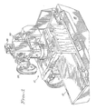
- FIG. 1 there is shown a simplified perspective view of an x-ray spot filming apparatus with which the present invention is particularly useful.
- the apparatus includes an x-ray table 10 and a spot filming apparatus 12.
- the spot filming apparatus 12 is supported above the table 10 on a column 14.
- the apparatus 12 can be moved vertically to raise or lower a film or an image responsive device with respect to the upper surface of the table 10.
- the table 10 is supported by a pedestal 16.
- the table surface 10 may be moved either laterally or longitudinally with respect to the spot film apparatus 12.
- the top of the table 10 constitutes a planar patient examining surface.
- the spot filming apparatus 12 and the support tower 14 are also capable of movement transversely with respect to the table top 10 by means of a support carriage (not shown).
- a conventional x-ray tube or source (not shown) attached to the support carriage is located within the table support table 16.
- the spot filming apparatus 12 is attached to the tower 14 by a support frame that includes a pair of transversely extending arms on which the spot filming apparatus 12 slides.
- the support arms are attached to the tower 14 for vertical movement in order to position the spot filming apparatus 12 with respect to a patient located on the table 10.
- Side support rails 20 support the spot filming apparatus for transverse movement with respect to the table 10.
- the spot filming apparatus 12 is manually moved between a rearward position and a forward position (the position shown in FIG. 1). In the rear position, the apparatus 12 is out of the direct line of the x-ray source radiation and is located in what is referred to as a non-operating position. In the forward or operating position, the spot filming apparatus 12 overhangs the patient examining surface on top of table 10.
- the spot filming apparatus 12 comprises a number of independent elements.
- the planar portion located adjacent the side rails 20 contains the apparatus for positioning x-ray film at predetermined locations for obtaining film images of a patient located on the table 10.
- the film locate within the portion 22 can be moved to different positions by motors positioned within the portion 22 which drive the film to desired locations. In at least one location, the film is moved out of the line of x-ray radiation so the x-ray radiation may pass through the portion 22 and enter into an electronic x-ray responsive image development apparatus 24.
- the apparatus 24 includes an image intensifier tube of a type well known in the art. Within the apparatus 24 there is located imaging optics and beam splitters for directing the image generated by the image intensifier tube to selected recording and presentation instruments. In FIG.
- one of the recording instruments is indicated at 26 as a cine camera for obtaining high speed photographic images of selected portions of a patient's anatomy.
- Electronic recording of images generated by the apparatus 24 is obtained by a TV camera 28 in conjunction with a magnetic recorder positioned at the upper end of the apparatus 24. Since it is also desirable for an operator to be able to continuously view the x-ray image being created, one or more television monitors are used with a TV camera 30 and recorder.
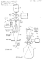
- FIG. 2 there is shown a functional diagram of the x-ray imaging portion of the apparatus illustrated in FIG. 1.
- the x-ray source is indicated at 32 for generating x-ray radiation 34 which passes through a collimator and shutter arrangement 36 to generate a directed beam of radiation onto a object positioned at the surface of table 10.
- the object is shown in FIG. 2 as a resolution pattern 38.
- the resolution pattern 38 is a sequence of elements which provide varying degrees of radiation absorption and also provide a pattern for presentation in order to determine the resolution of the system.
- the x-ray radiation beam 34 impinges on a phosphor face of an image intensifier tube 40 which converts the x-ray radiation to an optical image at a second or output face 42.
- a focus control 44 controls various grid elements in the imaging tube 40 so that the image can be appropriately focused at the surface 42.
- the optical image generated at surface 42 is projected through an objective lens 46 to an image gate 48.
- the image gate 48 includes a beam splitter (not shown) and appropriate electromechanical positioning apparatus for positioning the beam splitter so as to direct the optical image to both the TV camera 28, the cine camera 26 and photospot camera 30. All the cameras 26, 30 and 28 include camera lenses which collect the light emanating from the objective lens 46 and form an image of the output screen 42 on the pickup tube within the cameras 28 and 30 or on the film located within the camera 26. It should be noted here that the objective lens 46 and the lens of a corresponding camera operate together to form an infinite conjugate system.
- the conjugate ratio in an imaging system is the ratio of the expected subject distance as compared to the expected image distance.
- one of the conjugates is considered to be at infinity such that light entering the lens from this infinite conjugate has all the rays from a single point of the subject essentially parallel.
- the other conjugate that of the image distance, must be equal to the focal length of the lens. While lenses designed to have one conjugate infinitely long will work at other object image distances, their maximum resolution is realized when they are used at the conjugates for which they were designed. If one of the lenses is to be used as a collimating lens, which means that the infinitely long conjugate is in image space, then the object for this lens must be at the focal point of the lens.
- the output screen 42 of the tube 40 is located at the focal point of the objective lens so that all of the rays originating from any one point of the phosphor on the output screen emerge parallel from the lens.
- the lens 46 comprises a plurality of individual elements and may have as many as seven to nine individual glass elements in order to achieve the very high correction of aberration.
- Such an arrangement would require forty different variables be considered in the design of the lens, including for example, the radius of curvature of each surface of each of the nine elements plus the air space between the elements, the index of refraction of each element and the disbursive power of each element.
- the camera lens In addition to the objective lens 46, the camera lens must also operate to collect the light emanating from the objective lens 46 and form an image of the output screen on either a pick-up tube in the camera 28 or on a film in the camera 26.
- the infinite distance conjugate of the lens is on the object side. The image will therefor be formed at the focal plane of the camera lens.
- the combination of camera lens and objective lens causes light originating from a source at the focal plane of the objective lens to be projected as a family of parallel beams into the camera lens which then forms an image of the source at its focal plane.
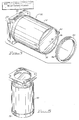
- FIG. 3 there is shown a perspective view of an image evaluation apparatus for in situ quantitative and qualitative evaluation of the imaging apparatus 12 of FIG. 1.
- the tool indicated generally at 50 comprises a generally cylindrical elongated housing 52 having one end attached to a substantially flat mounting base plate 54.
- a longitudinal axis 55 of housing 52 is normal to the plane of the mounting surface of the plate 54.
- a second end of the housing 52 has a slightly enlarged opening which has been machined to form an internal shoulder or shelf on which a light diffuser 56 may be positioned.
- the internal shoulder is indicated by the dashed lines 58.
- the retaining ring 60 has a circular groove 64 about its outer periphery.
- the thumb screws 60 when tightened will extend into the groove so as to hold the ring firmly in position against the light diffuser 56.
- the mounting plate 54 is machined to fit precisely square against the mounting bracket to which each of the image recording devices such as the cameras 26, 28 and 30 are normally attached. In this manner, the image which would normally be presented to the cameras is focused through the apparatus 50 and appears on the light diffuser 56. The focusing of the image onto the diffuser 56 is accomplished by an objective lens or set of lenses 72 (see FIG. 4) located in the apparatus 50 adjacent the mounting plate 54.
- the lenses are designed to provide for the transmittal of light from the objective lens 46 in a path which is essentially parallel from any point in the image so that the light at the diffuser 56 is not focused to a specific point as would occur with a standard camera lens.
- the lens 72 has a focal point of infinity.
- FIG. 4 there is shown a cross sectional view of a portion of the imaging apparatus 12 and the image evaluation apparatus 50 in an operative arrangement.
- the image generated by the image tube 40 is focused by the objectivelens 46 through the image gate 48.
- a beam splitter 70 which divides the light emanating from lens 46 into one portion which is transmitted to the camera 26 and a second portion which is transmitted to the image evaluation apparatus 50.
- the beam splitter 70 is moved completely out of the beam such that all of the light emanating from the lens 46 passes to the apparatus 50.
- the light is transmitted through its lens 72 which assures that the light rays are focussed on the diffuser 56.
- the design of objective lenses such as 72 for parallel light transmission is well known to those skilled in the art.
- a light impervious plate 74 is positioned over the light diffuser 56 to block external light and prevent such light from affecting the validity of light intensity readings taken across the diffuser 56.
- the plate 74 has a plurality of apertures formed therethrough for allowing a light sensor 76 to be placed in position to read light at a specific spot on the diffuser 56.
- the signals generated by the light sensor 76 are provided to a meter 78 which provides a read out of the light intensity on the monitored spot on the diffuser 56.
- a sequence of light intensity values can be taken at various selected areas on the diffiser 56.
- such areas might include the fringe areas around the periphery of the image and a central reading at the center of the plate 56.
- the system arrangement illustrated in FIG. 4 allows image system parameters such as conversion factor, contrast ratio and light output uniformity to be quantitatively measured through the image transmission path of apparatus 12.
- the image evaluation apparatus 50 in the arrangement illustrated can also be used as an alignment tool for the entire image system including the optics and image gate 48.
- the light diffuser 56 may be constructed in various alternative forms.
- the diffuser 56 may be a simple light diffusing plate.
- the light diffuser may have various types of graticles inscribed on the plate to enable precise measurement of image size and position. A complete set of graticles for evaluating all of the components of the imaging system would require several different patterns.
- the plate 74 acts as a guide plate and a support for the spot photometer light sensor 76. It provides repeatability of sensor placement with respect to a projected image. While a two hole plate 4 may be utilized and thus only two measurements required for contrast ratio measurement, the plate 74 requires at least six holes for uniformity measurement and measurement of cardiovascular phantom images. The four middle holes structured around a center hole are located proportional to 50% radius of the image to be measured. The outer hole is located proportional to the edge of the image to be measured.
- One of the graticles mentioned above is for use as light diffuser 56, six of the graticles are specifically designed for alignment of the television camera and equipment and two for image tube sizing and gate alignment.
- the image evaluation apparatus 50 is utilized as a light source rather than as illustrated in FIG. 4.
- the plate 74 is replaced with a flat plate electroluminescent lamp 78 (shown in FIG. 5) whose intensity can be precisely controlled.
- the TV camera 28 or 30 is then connected to the mounting plate 54 so that the image projected to the camera is that image appearing on the graticle or light diffuser 56.
- One of the graticles may be, for example, a multiburst graticle with incremental sets of television resolution measurement lines from side to side.
- Such television patterns are well known in the TV art.
- Other forms of graticles for use in aligning cameras may include a resolution burst, with incremental sets of television resolution measurement lines with the highest resolution in the center, a cross-hatch pattern, a ten step linear grey scale, a star and resolution wedge pattern and a beam alignment pattern. While these particular patterns are not unique to this invention, the preparation of such patterns on a graticle for displaying the patterns to a television camera for camera alignment purposes using the present invention is considered to be a novel application.
- graticles In addition to the graticles mentioned above, three further graticles are also utilized in aligning the imaging system. Two of the graticles include sizing rings and diffuser for adjusting the system optics for precise image size and a standard flat field low density light diffusing plate for evaluating the operation of the intensifier tube 40.
- the detachable electroluminescent light source is shown attached to the image evaluation apparatus 50 in FIG. 5.
- the light source 78 provides a uniform light of approximately 540 nanometers with a maximum intensity of 40 foot/Lamberts when operated from a 970Hz voltage source.
- the tool When the image evaluation apparatus 50 is attached to the imaging system 12 as shown in FIG. 4, the tool may be used to focus, size, center, align the gate 48 and measure the light output of the image system or image intensifier 40.
- the tool 50 When the tool 50 is connected to operate as an image transmitter as is shown in FIG. 5, it may be used to align, set up and evaluate a TV camera system and to align and focus photographic cameras.
- the graticles or light diffusing plates 56 are precision optical devices which must be accurately positioned in the focal plane of the tool.
- the graticles in a preferred embodiment are chromium deposited on one side of a glass base.
- the grey scale graticle is an emulsion pattern sealed between two glass plates.
- the image evaluation apparatus 50 is precisely designed to provide proper focusing and resolution of images generated by the image intensifier tube when mounted in the position of a recording instrument such as the camera 28, the adjustment of an image displayed on the apparatus 50 at the diffuser 56 is performed as a standard alignment of the imaging system 12.
- the focus of the image generted by the tube 40 is achieved by appropriate adjustment of the focus control 44 which varies the voltages on the various grid elements in the tube 40.
- Sizing of the image generated by the image tube 40 is determined by placing a sizing graticle in the position of the diffuser 56 and adjusting the appropriate grid voltages on the tube 40.
- Optical focus is achieved by adjusting the position of the objective lens 46.
- the image evaluation apparatus 50 is normally placed in the position of the cine camera 26.
- the intensity of the light reflected from the beam splitter 70 can then be measured by utilizing diffuser 56 with an appropriate guide plate 74 installed to allow measurement of light intensity at predetermined positions on the diffuser 56.
- the light meter sensor 76 provides a measurement of light intensity. If a prior measurement of system performance has been done by placing the image evaluation apparatus 50 along an axial direction of light travel as shown in FIG. 4, then any non-uniformities generated at the non-axial port such as that held by the camera 26, will indicate a problem or defect in the beam splitter 70, and replacement of the gate 48 or splitter 70 may be required.
- the image evaluation apparatus 50 also provides a means for measuring the uniformity of the field generated by the x-ray system. Field uniformity may be affected by x-ray tube problems, lack of uniformity in the beam splitter 70, vignetting caused by the optics 46 and non-uniformities of the image tube 40.
- Field uniformity may be affected by x-ray tube problems, lack of uniformity in the beam splitter 70, vignetting caused by the optics 46 and non-uniformities of the image tube 40.
- the image evaluation tool 50 By placing the image evaluation tool 50 on an axial port without the beam splitter 70 in the field of view, the image tube 40, optics 46 and x-ray source 32 may be evaluated.
- a cardiovascular phantom of a type well known in the art is placed in position on the table 10 and exposed to x-rays which are detected by image tube 40.
- the relative light output corresponding to the different cardiovascular phantom areas as measured with the apparatus 50 can be plotted on a sensitometric curve of a film taken from the cardiovascular phantom, on which the cardiovascular phantom densities have been plotted, providing correlation between system and film performance. This correlation information can be stored and retrieved for reference at a later time when the system is again evaluated.
- a test of contrast ratio of the system can be performed by performing initial measurements on an operating imaging system and comparing those measurements to published image tube data and by comparing those measurements to the same system at a later time when performance has degraded.
- the conversion factor of the system i.e., the ratio of radiation input to light output, can also be measured a new imaging system and stored for later use in determining the operation of the same system when the image has deteriorated.
- the image evaluation apparatus 50 is useful in evaluating the system by providing a means for aligning the image intensifier image and the image optics to achieve a desired image quality. Furthermore, by providing a means of obtaining measurements of a satisfactory operating system, the system can later be quantitatively evaluated to determine whether problems exist when image quality has deteriorated. By simply measuring selected quantities and comparing those quantities with values representative of proper operation, it can be determined whether the image tube 40, the optical system 46 or the image gate 48 is defective. Still further, by utilizing the image evaluation apparatus 50 as a light source for generating an image having a predetermined quality and light intensity, the operation of camera systems connected to the imaging system 12 can also be evaluated and aligned.
Landscapes
- Health & Medical Sciences (AREA)
- Life Sciences & Earth Sciences (AREA)
- Engineering & Computer Science (AREA)
- General Health & Medical Sciences (AREA)
- Medical Informatics (AREA)
- Radiology & Medical Imaging (AREA)
- Surgery (AREA)
- High Energy & Nuclear Physics (AREA)
- Physics & Mathematics (AREA)
- Nuclear Medicine, Radiotherapy & Molecular Imaging (AREA)
- Optics & Photonics (AREA)
- Pathology (AREA)
- Toxicology (AREA)
- Biomedical Technology (AREA)
- Heart & Thoracic Surgery (AREA)
- Molecular Biology (AREA)
- Biophysics (AREA)
- Animal Behavior & Ethology (AREA)
- Public Health (AREA)
- Veterinary Medicine (AREA)
- Radiography Using Non-Light Waves (AREA)
- Testing Of Optical Devices Or Fibers (AREA)
- X-Ray Techniques (AREA)
- Apparatus For Radiation Diagnosis (AREA)
- Image-Pickup Tubes, Image-Amplification Tubes, And Storage Tubes (AREA)
- Analysing Materials By The Use Of Radiation (AREA)
Applications Claiming Priority (2)
| Application Number | Priority Date | Filing Date | Title |
|---|---|---|---|
| US06/850,515 US4697075A (en) | 1986-04-11 | 1986-04-11 | X-ray imaging system calibration using projection means |
| US850515 | 1986-04-11 |
Publications (2)
| Publication Number | Publication Date |
|---|---|
| EP0240932A1 true EP0240932A1 (de) | 1987-10-14 |
| EP0240932B1 EP0240932B1 (de) | 1991-09-18 |
Family
ID=25308347
Family Applications (1)
| Application Number | Title | Priority Date | Filing Date |
|---|---|---|---|
| EP87104860A Expired - Lifetime EP0240932B1 (de) | 1986-04-11 | 1987-04-02 | Kalibrierung eines Röntgenstrahlabbildungssystem und Vorrichtung dazu |
Country Status (5)
| Country | Link |
|---|---|
| US (1) | US4697075A (de) |
| EP (1) | EP0240932B1 (de) |
| JP (1) | JPS6345528A (de) |
| AU (1) | AU585146B2 (de) |
| DE (1) | DE3773032D1 (de) |
Families Citing this family (15)
| Publication number | Priority date | Publication date | Assignee | Title |
|---|---|---|---|---|
| US4697075A (en) * | 1986-04-11 | 1987-09-29 | General Electric Company | X-ray imaging system calibration using projection means |
| US4882494A (en) * | 1988-02-26 | 1989-11-21 | Michael D. Duncan | Apparatus and method for flooding a nuclear imaging device with radiation from an imaging source |
| JPH01262452A (ja) * | 1988-04-13 | 1989-10-19 | Tokyo Electron Ltd | X線検査装置 |
| FR2634094B1 (fr) * | 1988-07-05 | 1992-04-10 | Gen Electric Cgr | Appareil a rayons x a visualisation de la geometrie du faisceau de rayons x |
| JP3584624B2 (ja) * | 1996-07-22 | 2004-11-04 | 日本精工株式会社 | トルクセンサ |
| JP4026247B2 (ja) | 1998-10-01 | 2007-12-26 | 日本精工株式会社 | トルクセンサ |
| CN100409102C (zh) * | 2005-03-07 | 2008-08-06 | 上海微电子装备有限公司 | 步进扫描投影光刻机中的杂散光原位检测方法 |
| US7639861B2 (en) * | 2005-09-14 | 2009-12-29 | Cognex Technology And Investment Corporation | Method and apparatus for backlighting a wafer during alignment |
| US8162584B2 (en) | 2006-08-23 | 2012-04-24 | Cognex Corporation | Method and apparatus for semiconductor wafer alignment |
| US8016199B2 (en) * | 2006-12-14 | 2011-09-13 | Cognex Corporation | Illumination devices for image acquisition systems |
| CN100559284C (zh) * | 2008-01-21 | 2009-11-11 | 上海微电子装备有限公司 | 一种光刻机杂散光的自动测量方法 |
| US8139231B2 (en) * | 2008-05-01 | 2012-03-20 | Cognex Corporation | Machine vision technique for manufacturing semiconductor wafers |
| US8570516B2 (en) * | 2008-09-12 | 2013-10-29 | Cognex Corporation | Infrared direct illumination machine vision technique for semiconductor processing equipment |
| US8189194B2 (en) * | 2008-09-12 | 2012-05-29 | Cognex Corporation | Direct illumination machine vision technique for processing semiconductor wafers |
| CN101968545B (zh) * | 2010-09-14 | 2012-10-17 | 中国原子能科学研究院 | 基于具有辐射记忆功能的光致发光图像板的辐射成像系统 |
Citations (6)
| Publication number | Priority date | Publication date | Assignee | Title |
|---|---|---|---|---|
| US3491239A (en) * | 1965-09-22 | 1970-01-20 | Gen Electric | X-ray image amplifier system with automatic exposure control |
| DE2652319A1 (de) * | 1975-11-25 | 1977-05-26 | Philips Nv | Roentgenanlage mit belichtungsautomat |
| US4335307A (en) * | 1980-04-21 | 1982-06-15 | Technicare Corporation | Radiographic apparatus and method with automatic exposure control |
| GB2105032A (en) * | 1981-08-13 | 1983-03-16 | Philips Nv | X-ray generator incorporating automatic correction of a dose-determining exposure parameter |
| US4400827A (en) * | 1981-11-13 | 1983-08-23 | Spears James R | Method and apparatus for calibrating rapid sequence radiography |
| US4442537A (en) * | 1981-05-18 | 1984-04-10 | Siemens Aktiengesellschaft | Diagnostic x-ray installation |
Family Cites Families (3)
| Publication number | Priority date | Publication date | Assignee | Title |
|---|---|---|---|---|
| US3558893A (en) * | 1967-01-30 | 1971-01-26 | Picker Corp | X- and gamma-ray sensitive image intensification tube |
| US4511927A (en) * | 1983-01-10 | 1985-04-16 | National Viewtech Corp. | Liquid coupling system for video projectors |
| US4697075A (en) * | 1986-04-11 | 1987-09-29 | General Electric Company | X-ray imaging system calibration using projection means |
-
1986
- 1986-04-11 US US06/850,515 patent/US4697075A/en not_active Expired - Fee Related
-
1987
- 1987-04-02 EP EP87104860A patent/EP0240932B1/de not_active Expired - Lifetime
- 1987-04-02 DE DE8787104860T patent/DE3773032D1/de not_active Expired - Lifetime
- 1987-04-09 JP JP62085914A patent/JPS6345528A/ja active Granted
- 1987-04-10 AU AU71411/87A patent/AU585146B2/en not_active Ceased
Patent Citations (6)
| Publication number | Priority date | Publication date | Assignee | Title |
|---|---|---|---|---|
| US3491239A (en) * | 1965-09-22 | 1970-01-20 | Gen Electric | X-ray image amplifier system with automatic exposure control |
| DE2652319A1 (de) * | 1975-11-25 | 1977-05-26 | Philips Nv | Roentgenanlage mit belichtungsautomat |
| US4335307A (en) * | 1980-04-21 | 1982-06-15 | Technicare Corporation | Radiographic apparatus and method with automatic exposure control |
| US4442537A (en) * | 1981-05-18 | 1984-04-10 | Siemens Aktiengesellschaft | Diagnostic x-ray installation |
| GB2105032A (en) * | 1981-08-13 | 1983-03-16 | Philips Nv | X-ray generator incorporating automatic correction of a dose-determining exposure parameter |
| US4400827A (en) * | 1981-11-13 | 1983-08-23 | Spears James R | Method and apparatus for calibrating rapid sequence radiography |
Also Published As
| Publication number | Publication date |
|---|---|
| AU7141187A (en) | 1987-10-15 |
| JPS6345528A (ja) | 1988-02-26 |
| DE3773032D1 (de) | 1991-10-24 |
| US4697075A (en) | 1987-09-29 |
| AU585146B2 (en) | 1989-06-08 |
| EP0240932B1 (de) | 1991-09-18 |
| JPH0355772B2 (de) | 1991-08-26 |
Similar Documents
| Publication | Publication Date | Title |
|---|---|---|
| US4697075A (en) | X-ray imaging system calibration using projection means | |
| US5557598A (en) | Beam splitter inspection apparatus and method | |
| US5694214A (en) | Surface inspection method and apparatus | |
| US3721827A (en) | Arrangement for automatically focussing an optical instrument | |
| US5745548A (en) | Apparatus for and method of adjustably precalibrating the position of the focal spot of an X-ray tube for use in a CT scanner system | |
| US20040156480A1 (en) | Image quality vascular uniformity evaluation method and apparatus | |
| US4472826A (en) | X-Ray examination apparatus | |
| CN1108517A (zh) | 具有可调整一次射线遮光板的x射线仪 | |
| US4092669A (en) | Apparatus for measuring spatial data from recorded images | |
| US6346981B1 (en) | Lens testing device | |
| US4545678A (en) | Method and apparatus for testing lenses | |
| US4637720A (en) | Lens meter having a focusing indication system with divided-image registration focusing | |
| US4758731A (en) | Method and arrangement for aligning, examining and/or measuring two-dimensional objects | |
| NL8902975A (nl) | Werkwijze en inrichting voor het onderzoeken van optische stelsels. | |
| RU2855923C1 (ru) | Микроденситометр | |
| JP2004132858A (ja) | 光学系の光学性能を測定する装置及び方法 | |
| US6853438B2 (en) | Test apparatus and method to check the exposure quality of exposed film | |
| JPS6235052B2 (de) | ||
| CN210863102U (zh) | 一种自聚焦透镜的像面球差分布测试装置 | |
| JP2000009423A (ja) | 光学機器のピント調整装置 | |
| JPH01501114A (ja) | 画像解析装置 | |
| Wojtowicz | A Television and Film Lens-Testing System | |
| Abbott | Practical Aspects Of Transfer Function Measurement | |
| Considine et al. | Image digitizer system design considerations | |
| JPH01262453A (ja) | 蓄積性蛍光板を利用したx線回折装置における回折x線強度の読取り方法 |
Legal Events
| Date | Code | Title | Description |
|---|---|---|---|
| PUAI | Public reference made under article 153(3) epc to a published international application that has entered the european phase |
Free format text: ORIGINAL CODE: 0009012 |
|
| AK | Designated contracting states |
Kind code of ref document: A1 Designated state(s): CH DE FR GB IT LI NL SE |
|
| 17P | Request for examination filed |
Effective date: 19880318 |
|
| 17Q | First examination report despatched |
Effective date: 19900712 |
|
| GRAA | (expected) grant |
Free format text: ORIGINAL CODE: 0009210 |
|
| AK | Designated contracting states |
Kind code of ref document: B1 Designated state(s): CH DE FR GB IT LI NL SE |
|
| PG25 | Lapsed in a contracting state [announced via postgrant information from national office to epo] |
Ref country code: SE Effective date: 19910918 Ref country code: IT Free format text: LAPSE BECAUSE OF FAILURE TO SUBMIT A TRANSLATION OF THE DESCRIPTION OR TO PAY THE FEE WITHIN THE PRE;WARNING: LAPSES OF ITALIAN PATENTS WITH EFFECTIVE DATE BEFORE 2007 MAY HAVE OCCURRED AT ANY TIME BEFORE 2007. THE CORRECT EFFECTIVE DATE MAY BE DIFFERENT FROM THE ONE RECORDED.SCRIBED TIME-LIMIT Effective date: 19910918 |
|
| REF | Corresponds to: |
Ref document number: 3773032 Country of ref document: DE Date of ref document: 19911024 |
|
| EN | Fr: translation not filed | ||
| PG25 | Lapsed in a contracting state [announced via postgrant information from national office to epo] |
Ref country code: FR Effective date: 19920207 |
|
| PGFP | Annual fee paid to national office [announced via postgrant information from national office to epo] |
Ref country code: CH Payment date: 19920317 Year of fee payment: 6 |
|
| PGFP | Annual fee paid to national office [announced via postgrant information from national office to epo] |
Ref country code: DE Payment date: 19920410 Year of fee payment: 6 |
|
| PGFP | Annual fee paid to national office [announced via postgrant information from national office to epo] |
Ref country code: NL Payment date: 19920430 Year of fee payment: 6 |
|
| PLBE | No opposition filed within time limit |
Free format text: ORIGINAL CODE: 0009261 |
|
| STAA | Information on the status of an ep patent application or granted ep patent |
Free format text: STATUS: NO OPPOSITION FILED WITHIN TIME LIMIT |
|
| 26N | No opposition filed | ||
| REG | Reference to a national code |
Ref country code: GB Ref legal event code: 746 |
|
| REG | Reference to a national code |
Ref country code: FR Ref legal event code: ST |
|
| PG25 | Lapsed in a contracting state [announced via postgrant information from national office to epo] |
Ref country code: LI Effective date: 19930430 Ref country code: CH Effective date: 19930430 |
|
| PG25 | Lapsed in a contracting state [announced via postgrant information from national office to epo] |
Ref country code: NL Effective date: 19931101 |
|
| NLV4 | Nl: lapsed or anulled due to non-payment of the annual fee | ||
| REG | Reference to a national code |
Ref country code: CH Ref legal event code: PL |
|
| PG25 | Lapsed in a contracting state [announced via postgrant information from national office to epo] |
Ref country code: DE Effective date: 19940101 |
|
| PGFP | Annual fee paid to national office [announced via postgrant information from national office to epo] |
Ref country code: GB Payment date: 19940331 Year of fee payment: 8 |
|
| PG25 | Lapsed in a contracting state [announced via postgrant information from national office to epo] |
Ref country code: GB Effective date: 19950402 |
|
| GBPC | Gb: european patent ceased through non-payment of renewal fee |
Effective date: 19950402 |