EP0240650B1 - Glühkerze mit zwei Glühwendeln für Dieselmotoren - Google Patents
Glühkerze mit zwei Glühwendeln für Dieselmotoren Download PDFInfo
- Publication number
- EP0240650B1 EP0240650B1 EP19870100292 EP87100292A EP0240650B1 EP 0240650 B1 EP0240650 B1 EP 0240650B1 EP 19870100292 EP19870100292 EP 19870100292 EP 87100292 A EP87100292 A EP 87100292A EP 0240650 B1 EP0240650 B1 EP 0240650B1
- Authority
- EP
- European Patent Office
- Prior art keywords
- sheath
- glow plug
- coils
- temperature
- heating
- Prior art date
- Legal status (The legal status is an assumption and is not a legal conclusion. Google has not performed a legal analysis and makes no representation as to the accuracy of the status listed.)
- Expired
Links
Images

Classifications
-
- F—MECHANICAL ENGINEERING; LIGHTING; HEATING; WEAPONS; BLASTING
- F23—COMBUSTION APPARATUS; COMBUSTION PROCESSES
- F23Q—IGNITION; EXTINGUISHING-DEVICES
- F23Q7/00—Incandescent ignition; Igniters using electrically-produced heat, e.g. lighters for cigarettes; Electrically-heated glowing plugs
- F23Q7/001—Glowing plugs for internal-combustion engines
Definitions
- the present invention relates to glow plugs for diesel engines of motor vehicles of the type comprising a hollow metal body, a current feeder and a tubular metal sheath, which is secured to the inside of said body and closed at the tip, in which sheath a portion of the current feeder and two series connected electrical wire coils, one for heating and the other one for controlling the supply current, are inserted and embedded in an insulating powder, said control coil being inserted into the sheath zone which is surrounded by said body for a portion higher than one half of its length, preferably from 50 to 70% of its length.
- the heating coil performs the function of causing the sheath to glow to sufficiently heat the combustion chamber or precombustion chamber, into which the sheath projects in order to facilitate the starting of the engine, particularly at low ambient temperatures.
- the control coil performs the function of limiting the intensity of current that flows into the two coils when the temperature increases, in order to avoid the overheating and therefore the burnout of one or both coils.
- the control is made of a filament having a PTC characteristic i.e. a very high positive temperature coefficient of resistance whereas the heating coil is made of an alloy of higher resistivity whereby, during the preheating time, the control coil, that is at ambient temperature, has a low electrical resistance for allowing the passage of a high supply current into the heating coil and thus a temperature increase of the sheath is achieved; but, owing to the temperature increase of the control coil, this increase being caused substantially by the thermal influence of the heating coil, an increase of its electrical resistance and therefore a reduction of the supply current occurs, resulting in the control of the maximum sheath temperature, that is kept within the pre-established limits.
- a PTC characteristic i.e. a very high positive temperature coefficient of resistance
- the heating coil is made of an alloy of higher resistivity
- the well-known glow plugs of this type show heating curves of the sheath usually included between two limit curves: the upper curve (see A of Figure 3) tending, in steady state, to a maximum pre-established temperature, usually amouting to about 1100°C, and the other lower curve (see B of Figure 3) usually tending, in steady state, to about 1000°C.
- the heating coil thermally influences the control coil since the beginning of current supply period and that the heating of said control coil is influenced by various parameters, such as the filament diameter of the coils, turns pitch of the coils, winding diameter of the coils, relative distance between the coils, powder compactness, etc., which change from one glow plug to any other glow plug owing to the unavoidable manufacturing tolerances of coils and/or assembly of the same ones into the sheath.
- the starting of the engine can be irregular or prevented when the ambient temperatures are under 0°C and this occurs because the sheath reaches the temperature necessary for the ignition of the air/gasoil mixture only after a preheating time longer than the nominal foreseen time.
- a glow plug of the type including a tubular sheath containing two electrical coils connected in series is disclosed by the Japanese Patent Specification JP-A-57-26326.
- the control coil is disposed so that 50 to 75% of its length is positioned into the body of glow plug.
- the coils are directly connected with one another so that the heating coil thermally influences the control coil, whereby the drawbacks for the mixture ignition at start of the engine due to the variable temperature tolerances of the heating curves of the sheath are not eliminated.
- the main object of the present invention is that of reducing the tolerance range of heating curves of the sheath of dual coil glow plugs of the above mentioned type with the aim of ensuring a better control of maximum steady temperature and so reducing the preheating times of the engine, particularly when the ambient temperature is near or under 0°C.
- Another object of the present invention is to manufacture the double coil by an automated process for reducing the production cost of the glow plugs.
- a glow plug of the type as specified in the preamble of the specification characterized in that the heating coil and the control coil are connected with one another by means of an apposite or proper electrically conductive spacer element having a low thermal conductivity and a length of some millimeters sufficient to obtain a substantial thermal insulation between said coils, whereby the control coil is no more thermally influenced by the heating coil heat and its temperature is substantially that caused by the supply current flowing through it.
- the heating curves of glow plugs according to the invention are a function only of the control coil parameters and, accordingly, these curves are situated in a very reduced temperature range, that is kept near and under the upper limit curve and, in steady state, the temperature tolerance is reduced of about 50% of the temperature tolerance of the heating curves of known glow plugs.
- connection of the coils is obtained by means of an intermediate element
- the manufacturing of the double coil can be carried out advantageously using simple automatic systems, avoiding in this manner the costly Laser or plasma welding processes, that were required until to-day for connecting directly the two ends of coils.
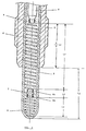
- the glow plug comprises a hollow metal body 1, a current feeder 2 and a tubular metal sheath 3, which, at one end, is secured to the inside of body 1, at the other end, protrudes from the body and is closed at its tip.
- the sheath portion having the length Lg protruding from the body 1 forms the glow tube that ends in the combustion chamber or pre-combustion chamber of a Diesel engine.
- the first coil 5 performs the function of heating the sheath for bringing the latter to glow and so promote the start of the engine
- the second coil 6 performs the function of controlling the current supply flowing across the coils in order to prevent the coils reaching inadmissible high temperatures.
- the control coil 6 is inserted for about 2/3 of its length (2/3 Lc) into the sheath zone that is surrounded by the body 1.
- the opposite ends of the two coils 5, 6 are connected respectively to the sheath tip and to the end of the current feeder 2.
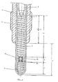
- the other two ends of coils 5 and 6, that is ones marked 5a and 6a, are connected with one another by means of a spacer element 7 or 8, that is electrically conductive and has a low thermal conductivity.
- the element 7 or 8 that is made of stainless steel (Ni-Cr alloy) and has a length Ld of some millimeters, gives a spacing between the two coils and thus ensuring a substantial thermal separation of the same coils.
- the heat transmission from the heating coil 5 to the control coil 6 is obstructed because, on one hand, the direct transmission towards the control coil is prevented by the presence of the spacer element 7 or 8, having a low thermal conductivity and, on the other hand, the indirect heat transmitted towards the control coil is dissipated towards the combustion chamber through the sheath 3 and towards the engine head through said sheath and the plug body 1.
- the heating cumin of glow plugs vary in a temperature range very reduced in comparison with the temperature range of conventional glow plugs.
- the comparison is shown in Figure 3, where the limit curves A and B define the temperature tolerance range of known glow plugs, while the curves A and C define the temperature tolerance range, represented in dotted lines, of glow plugs made in accordance with the invention.
- the upper limit curve A tends to 1100°C temperature, that is the maximum pre-established temperature the sheath must not exceed, in steady state, to avoid compromising the coils life
- the other two lower limit curves B and C related, respectively, to known glow plugs and to glow plugs according to the invention, in steady condition, tend, the first one to 1000°C temperature, that is the minimum temperature the sheath must reach for assuring at start the mixture ignition even at very low ambient temperatures and within acceptable preheating times and the second one to a higher temperature of 1050°C.
- the sheath temperature during the first supply period of the coils undergoes a very quick increase with a very high temperature gradient of about 90°C/1 ⁇ and thus the heating curve is very steep and this happens as, during this period, a minimum control (regulation) of the supply current is carried out by the control coil 6. Indeed, owing to the substantial thermal insulation of the control coil 6, a substantial increase of its resistance does not occur.
- the sheath temperature undergoes a very low increase with a very low temperature gradient of about 2°C/1 ⁇ and this occurs because, during this second period, a supply current regulation (reduction) is carried out by the control coil which has undergone in the meantime to a temperature increase and thus its resistance was increased under the action of the current flowing through it and not as a consequence of the heating coil thermal influence which is negligible.
- the heating curve of the sheath is promptly stabilized under the maximum pre-established temperature value (1100°C), the temperature range being a function of the only control coil parameters.
- a glow plug having: a spacer tubular element 8 showing a length Ld predominant in comparison with the transversal dimension, Ld being comprised between 8 and 18 mm and O/D comprised between 2 and 3 mm; a control coil 6 of a length Lc; a heating coil 5 of a length Lr, the length ratio Lc/Lr being higher than 3 (i.e. Lc/Lr > 3); and a sheath 3 protruding from the body 1 for a length Lg comprised between 20 and 30 mm.
- the spacer element 7 or 8 which, as above said, has a low thermal conductivity, preventing the heat transmission from the heating coil towards the control coil causes a temperature increase at the sheath end.
- the hottest part of the sheath is located at a distance included from 1 to 1.5 mm from the end of the sheath, differently from what occurs in known two coil glow plugs in which the hottest part is located at a distance of about 3 mm from the end.
- the temperature increase at the sheath end has the advantage of positioning the more incandescent part of the sheath in the zone closest to the fuel (gasoil) jet and therefore causing a quicker and complete ignition of air/gasoil mixture.
- the graph of Figure 3 shows the reduction of preheating times: in fact the curve C reaches the temperature of 1000°C in a time lower than 30 sec and the temperature of 850°C in 6-7 sec instead of respectively 30 sec and 6-8 sec that are the times required for reaching the same temperature with a heating according to the curve B.
- the Figure 4 shows the behaviour of the temperature Tc required to the sheath for causing the ignition of the mixture when the ambient temperature Ta changes.
- the heating temperature Tc increases passing, for example, from a heating temperature of about 800°C at an ambient temperature of + 10°C to a heating temperature of about 1100°C for an ambient temperature of-20°C. Therefore, the lower the ambient temperatures are, the longer the preheating times are. That is the times required for raising the sheath temperature to the necessary value for causing the mixture igntion are increased.
- the Figure 1 shows a spacer element consisting of a shaped pin 7, while the Figure 2 shows a spacer element consisting of a tubular or drilled element 8.
- the connection of the ends or terminal turns 5a and 6a of coils 5 and 6 with:he spacer element 7 is made by means of conventional electrical resistance welding, while the connection of these turns 5a and 6a with the tubular element 8 is made by squashing or radially compressing the ends of the tubular element after the terminal turns 5a, 6a of two coils 5, 6 have been inserted into the inside of said ends.
- any other electrical or mechanical anchoring system can be used according to practical hoc responsibilities.
Landscapes
- Engineering & Computer Science (AREA)
- Chemical & Material Sciences (AREA)
- Combustion & Propulsion (AREA)
- Mechanical Engineering (AREA)
- General Engineering & Computer Science (AREA)
- Resistance Heating (AREA)
Claims (5)
Applications Claiming Priority (4)
| Application Number | Priority Date | Filing Date | Title |
|---|---|---|---|
| IT1909986 | 1986-01-16 | ||
| IT19099/86A IT1204761B (it) | 1986-01-16 | 1986-01-16 | Candela ad incandescenza a due spirali per motori diesel di autoveicoli |
| IT849286 | 1986-09-29 | ||
| IT849286 | 1986-09-29 |
Publications (2)
| Publication Number | Publication Date |
|---|---|
| EP0240650A1 EP0240650A1 (de) | 1987-10-14 |
| EP0240650B1 true EP0240650B1 (de) | 1991-04-03 |
Family
ID=26326072
Family Applications (1)
| Application Number | Title | Priority Date | Filing Date |
|---|---|---|---|
| EP19870100292 Expired EP0240650B1 (de) | 1986-01-16 | 1987-01-12 | Glühkerze mit zwei Glühwendeln für Dieselmotoren |
Country Status (2)
| Country | Link |
|---|---|
| EP (1) | EP0240650B1 (de) |
| DE (1) | DE3768994D1 (de) |
Families Citing this family (3)
| Publication number | Priority date | Publication date | Assignee | Title |
|---|---|---|---|---|
| GB2220446B (en) * | 1988-04-06 | 1992-05-27 | Champion Spark Plug Europ | Glow plug for internal combustion engine |
| IT1258675B (it) * | 1992-12-18 | 1996-02-27 | Candela ad incandescanza con doppia spirale di controllo per motori diesel | |
| DE102010029047A1 (de) * | 2010-05-18 | 2011-11-24 | Robert Bosch Gmbh | Verfahren und Vorrichtung zur Reduzierung der Temperaturtoleranz von Glühstiftkerzen |
Family Cites Families (3)
| Publication number | Priority date | Publication date | Assignee | Title |
|---|---|---|---|---|
| US4549071A (en) * | 1981-04-30 | 1985-10-22 | Jidosha Kiki Co., Ltd. | Glow plug for use in diesel engine |
| US4423309A (en) * | 1982-06-28 | 1983-12-27 | General Motors Corporation | Quick heat self regulating electric glow heater |
| JPS59231321A (ja) * | 1983-06-13 | 1984-12-26 | Ngk Spark Plug Co Ltd | 自己制御型グロ−プラグ |
-
1987
- 1987-01-12 EP EP19870100292 patent/EP0240650B1/de not_active Expired
- 1987-01-12 DE DE8787100292T patent/DE3768994D1/de not_active Expired - Lifetime
Also Published As
| Publication number | Publication date |
|---|---|
| DE3768994D1 (de) | 1991-05-08 |
| EP0240650A1 (de) | 1987-10-14 |
Similar Documents
| Publication | Publication Date | Title |
|---|---|---|
| CA1089307A (en) | Glow-plug | |
| CA1207620A (en) | Quick heat self regulating electric glow heater | |
| US4549071A (en) | Glow plug for use in diesel engine | |
| US6064039A (en) | Glow plug with small-diameter sheath tube enclosing heating and control coils | |
| US6878903B2 (en) | Glow plug | |
| US4682008A (en) | Self-temperature control type glow plug | |
| PL190854B1 (pl) | Grzałka ceramiczna | |
| EP0229677A2 (de) | Glühkerze | |
| JP2001330249A (ja) | グロープラグ及びその製造方法 | |
| US4661686A (en) | Dual line ceramic glow plug | |
| US5251589A (en) | Hot tip glow plug and method for making | |
| US4650963A (en) | Ceramic glow plug | |
| EP0240650B1 (de) | Glühkerze mit zwei Glühwendeln für Dieselmotoren | |
| US5172664A (en) | Incandescent plug | |
| KR100819894B1 (ko) | 글로우 플러그 | |
| US4582980A (en) | Glow plug for diesel engines of motor vehicles | |
| EP0607872B1 (de) | Glühkerze für Dieselmotoren | |
| KR100670574B1 (ko) | 시이드형 글로우 플러그 | |
| GB2136504A (en) | Flame glow-in plug for preheating the intake air of internal combustion engine | |
| EP0438097B1 (de) | Glühstiftkerze für Dieselmotoren, insbesondere für Kraftfahrzeuge mit reduziertem Durchmesser des geschlossenen Glührohrendes | |
| EP0129676B1 (de) | Glühkerze mit einem schichtförmigen Heizwiderstand | |
| EP1207349B1 (de) | Keramische Glühkerze und Verfahren zur Herstellung derselben | |
| JP2793005B2 (ja) | 予熱プラグ | |
| JPS6350606Y2 (de) | ||
| USRE31908E (en) | Glow plug |
Legal Events
| Date | Code | Title | Description |
|---|---|---|---|
| PUAI | Public reference made under article 153(3) epc to a published international application that has entered the european phase |
Free format text: ORIGINAL CODE: 0009012 |
|
| AK | Designated contracting states |
Kind code of ref document: A1 Designated state(s): BE DE ES FR GB SE |
|
| 17P | Request for examination filed |
Effective date: 19880326 |
|
| 17Q | First examination report despatched |
Effective date: 19880718 |
|
| GRAA | (expected) grant |
Free format text: ORIGINAL CODE: 0009210 |
|
| AK | Designated contracting states |
Kind code of ref document: B1 Designated state(s): BE DE ES FR GB SE |
|
| REF | Corresponds to: |
Ref document number: 3768994 Country of ref document: DE Date of ref document: 19910508 |
|
| ET | Fr: translation filed | ||
| PLBI | Opposition filed |
Free format text: ORIGINAL CODE: 0009260 |
|
| 26 | Opposition filed |
Opponent name: BERU RUPRECHT GMBH & CO. KG Effective date: 19920103 |
|
| PLBN | Opposition rejected |
Free format text: ORIGINAL CODE: 0009273 |
|
| STAA | Information on the status of an ep patent application or granted ep patent |
Free format text: STATUS: OPPOSITION REJECTED |
|
| 27O | Opposition rejected |
Effective date: 19940322 |
|
| EAL | Se: european patent in force in sweden |
Ref document number: 87100292.9 |
|
| REG | Reference to a national code |
Ref country code: GB Ref legal event code: 732E |
|
| REG | Reference to a national code |
Ref country code: FR Ref legal event code: TP |
|
| REG | Reference to a national code |
Ref country code: ES Ref legal event code: PC2A |
|
| REG | Reference to a national code |
Ref country code: GB Ref legal event code: IF02 |
|
| PGFP | Annual fee paid to national office [announced via postgrant information from national office to epo] |
Ref country code: BE Payment date: 20020107 Year of fee payment: 16 |
|
| PGFP | Annual fee paid to national office [announced via postgrant information from national office to epo] |
Ref country code: SE Payment date: 20020117 Year of fee payment: 16 |
|
| PGFP | Annual fee paid to national office [announced via postgrant information from national office to epo] |
Ref country code: FR Payment date: 20020118 Year of fee payment: 16 |
|
| PGFP | Annual fee paid to national office [announced via postgrant information from national office to epo] |
Ref country code: DE Payment date: 20020205 Year of fee payment: 16 |
|
| PGFP | Annual fee paid to national office [announced via postgrant information from national office to epo] |
Ref country code: GB Payment date: 20021210 Year of fee payment: 17 |
|
| PG25 | Lapsed in a contracting state [announced via postgrant information from national office to epo] |
Ref country code: SE Free format text: LAPSE BECAUSE OF NON-PAYMENT OF DUE FEES Effective date: 20030113 |
|
| PGFP | Annual fee paid to national office [announced via postgrant information from national office to epo] |
Ref country code: ES Payment date: 20030127 Year of fee payment: 17 |
|
| PG25 | Lapsed in a contracting state [announced via postgrant information from national office to epo] |
Ref country code: BE Free format text: LAPSE BECAUSE OF NON-PAYMENT OF DUE FEES Effective date: 20030131 |
|
| PG25 | Lapsed in a contracting state [announced via postgrant information from national office to epo] |
Ref country code: DE Free format text: LAPSE BECAUSE OF NON-PAYMENT OF DUE FEES Effective date: 20030801 |
|
| EUG | Se: european patent has lapsed | ||
| PG25 | Lapsed in a contracting state [announced via postgrant information from national office to epo] |
Ref country code: FR Free format text: LAPSE BECAUSE OF NON-PAYMENT OF DUE FEES Effective date: 20030930 |
|
| REG | Reference to a national code |
Ref country code: FR Ref legal event code: ST |
|
| PG25 | Lapsed in a contracting state [announced via postgrant information from national office to epo] |
Ref country code: GB Free format text: LAPSE BECAUSE OF NON-PAYMENT OF DUE FEES Effective date: 20040112 |
|
| PG25 | Lapsed in a contracting state [announced via postgrant information from national office to epo] |
Ref country code: ES Free format text: LAPSE BECAUSE OF NON-PAYMENT OF DUE FEES Effective date: 20040113 |
|
| GBPC | Gb: european patent ceased through non-payment of renewal fee |
Effective date: 20040112 |
|
| REG | Reference to a national code |
Ref country code: ES Ref legal event code: FD2A Effective date: 20040113 |
|
| APAH | Appeal reference modified |
Free format text: ORIGINAL CODE: EPIDOSCREFNO |