EP0240650A1 - Glühkerze mit zwei Glühwendeln für Dieselmotoren - Google Patents
Glühkerze mit zwei Glühwendeln für Dieselmotoren Download PDFInfo
- Publication number
- EP0240650A1 EP0240650A1 EP87100292A EP87100292A EP0240650A1 EP 0240650 A1 EP0240650 A1 EP 0240650A1 EP 87100292 A EP87100292 A EP 87100292A EP 87100292 A EP87100292 A EP 87100292A EP 0240650 A1 EP0240650 A1 EP 0240650A1
- Authority
- EP
- European Patent Office
- Prior art keywords
- sheath
- spirals
- glow plug
- lenght
- spiral
- Prior art date
- Legal status (The legal status is an assumption and is not a legal conclusion. Google has not performed a legal analysis and makes no representation as to the accuracy of the status listed.)
- Granted
Links
- 238000010438 heat treatment Methods 0.000 claims abstract description 34
- 125000006850 spacer group Chemical group 0.000 claims abstract description 16
- 239000002184 metal Substances 0.000 claims description 6
- 238000003466 welding Methods 0.000 claims description 6
- 239000000843 powder Substances 0.000 claims description 3
- 238000004873 anchoring Methods 0.000 claims description 2
- 230000008901 benefit Effects 0.000 abstract description 3
- 238000004519 manufacturing process Methods 0.000 description 6
- 238000000034 method Methods 0.000 description 6
- 239000000203 mixture Substances 0.000 description 6
- 230000008569 process Effects 0.000 description 6
- 230000005540 biological transmission Effects 0.000 description 3
- 238000002485 combustion reaction Methods 0.000 description 2
- 238000005457 optimization Methods 0.000 description 2
- 230000009467 reduction Effects 0.000 description 2
- 229910000599 Cr alloy Inorganic materials 0.000 description 1
- 229940094070 ambien Drugs 0.000 description 1
- 230000008859 change Effects 0.000 description 1
- 238000010276 construction Methods 0.000 description 1
- 230000007423 decrease Effects 0.000 description 1
- 230000009977 dual effect Effects 0.000 description 1
- 230000008030 elimination Effects 0.000 description 1
- 238000003379 elimination reaction Methods 0.000 description 1
- 239000000446 fuel Substances 0.000 description 1
- 230000001788 irregular Effects 0.000 description 1
- 238000013021 overheating Methods 0.000 description 1
- 238000000926 separation method Methods 0.000 description 1
- 239000010935 stainless steel Substances 0.000 description 1
- 229910001220 stainless steel Inorganic materials 0.000 description 1
- ZAFYATHCZYHLPB-UHFFFAOYSA-N zolpidem Chemical compound N1=C2C=CC(C)=CN2C(CC(=O)N(C)C)=C1C1=CC=C(C)C=C1 ZAFYATHCZYHLPB-UHFFFAOYSA-N 0.000 description 1
Images


Classifications
-
- F—MECHANICAL ENGINEERING; LIGHTING; HEATING; WEAPONS; BLASTING
- F23—COMBUSTION APPARATUS; COMBUSTION PROCESSES
- F23Q—IGNITION; EXTINGUISHING-DEVICES
- F23Q7/00—Incandescent ignition; Igniters using electrically-produced heat, e.g. lighters for cigarettes; Electrically-heated glowing plugs
- F23Q7/001—Glowing plugs for internal-combustion engines
Definitions
- the present invention relates to glow plugs having two spirals for diesel engines of motor vehicles.
- the invention relates to glow plugs including an hollow metal body, a current feeder and a tubular metal sheath which is secured to said body and is closed at the tip, in which sheath a portion of the current feeder and two series connected electrical spirals, one for heating and the other one for controlling the supply current, are inserted and embedded in an insulating powder, wherein from 50 to 70% of the lenght of the cotrol spiral is inserted into the sheath zone surrounded by said body.
- the heating spiral performs the function of bringing the sheath to glow for sufficiently heating the combustion chamber or precombustion chamber, into which the sheath projects in order to facilitate the starting of the engine at low temperatures.
- control spiral performs the function of limiting the intensity of current that flows into the two spirals when the temperature increases in order to avoid the sheath overheating and therefore the burnout of one or both spirals.
- the control spiral comprises a filament having a very high positive temperature coef- .ficient of resistence with respect to that of the heating spiral, whereby, on starting the cold engine, the control spiral, that is at ambient temperature, has a low electric resistance for allowing the passage of a strong current into the heating spiral and thus a quick temperature increase of the sheath; alterwards, owing to the temperature increase of the said control spiral, this increase being caused substantially by the thermal influence of the heating spiral, an increase of its electical resistance occurs and therefore a reduction of the supply current, resulting in control of the maximum . sheath temperature that is kept within suitable limits.
- Known double spiral glow plugs show heating curves usually situated between two limit curves: the superior one, tending, in steady state, to a maximum temperature usually amounting to about 1100°C and, the other lower curve, tending, in steady state, usually to about 1000°C.
- the heating curves are very near to the lower limit curve, it can happen that the starting of the engine can be irregular or prevented when the ambient temperatures are below 0°C and this occurs because the sheath reaches the necessary temperature for the ignition of the air/gas oil mixture only after a prehating time higher that the nominal foreseen time.
- the main object of the present invention is that of reducting the tolerance range of heating curves of the sheath of dual spiral glow plugs of the above mentioned tipe with the aim of getting a better control of maximum steady temperature and so reducing the preheating times of the engine, when the ambien temperature is near or under 0°C.
- Another object of the present invention is to manufacture the double spiral by an automatized process for reducing the production costs of glow plugs.
- a glow plug which, according to the invention, is characterized in that the two spirals are connected to each another by means of an electrically conductive spacer element having a low thermal conductivity, and in that the lenght of such spacer element is comprised betheen 8 and 18 mm, the ratio betheen the lenght of the control spiral and the lenght of the heating spiral being higher than 3 and the projection of the sheath from the body having a lenght comprised betheen 20 and 30 mm.
- the thermal influence of the heating spiral on the control spiral is reduced to a minimum value, as, on the one hand, the two spirals are thermally separated by means of said spacer element and, on the other hand, the control i spiral is kept in thermal equilibrium with the external temperature thanks to the heat transmission that occurs through the plug body, so that the control spiral temperature is finally the temperature caused almost exclusively by the current flowing in the spirals.
- the heating curves of glow plugs according to the invention are situated in a very reduced range that is kept near and under the conventional superior limit curve and, in steady state, the temperature tolerance is reduced by about 50% of the temoerature tolerance of the heatino curves of known glow pluqs.
- connection of the two spirals is obtained by means of an intermediate element
- the manufacturing of the double spiral can be carried out advanta- geusly by simple automatic systems, so avoiding the costly Laser or plasma welding processes that were required until to-day for the direct connection of the two ends of spirals.
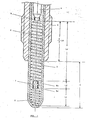
- the glow plug comprises an hollow metal body 1, a current feeder 2 and a tubular metal sheath 3, which, at one end, is secured to the interior of body 1 and, at the other end protrudes from the body and is closed at its tip.
- the sheath portion of lenght L g protruding from the body 1 forms the glow tube that ends in the combustion chamber or precombustion chamber of a Diesel engine.
- the first spiral has the function of heating the sheath for bringing the latter to glow and so promote the start of the engine while the second spiral has the function of controlling the supply current that flows the spirals in order to prevent the sheath reaching inadmissible high temperatures.
- Control spiral 6 is inserted for about 2/3 of its lenght (2/3 Lc) into the sheath zone that is surrounded by the body 1. The opposite ends of the two spirals 5, 6 are connected respectively to the sheath tip and to the end of the current feeder 2.
- the other two ends of spirals 5 and 6, that is the ones marked 5a and 6a are connected to one another by means of a spacer element 7 or 8 that is electrically conductive and has a low thermal conductivity.
- the element 7 or 8 that is made of stainless steel (Ni - Cr alloy) and has a lenght Ld of some millimeters, gives a spacing between the two spirals and thus a substantial thermal separation of the same and, on the other hand, owing to its low termal conductivity, reducts heat transmission, whereby, it minimizes the thermal influence of the heating spiral 5 on the control spiral 6.
- control spiral 6 is inserted for about 60 - 70% of its lenght Lc into the zone of the sheath 3 that is surrounded by the body 1, it occurs that the body transmit to outside the heat coming from the heating spiral mainly through the sheath, so minimizing further the thermal influence of the heating spiral on the control spiral.
- lenght of the control spiral that is placed in the interior of body should be selected in relation to optimization of the thermal equilibrium of the spiral with respect to external temperature.
- the heating curves of glow plugs vary in a range of temperature tolerance very reduced in comparison with the range of temperature of conventional glow plugs.
- the comparison is shown in Fig.3 where the limit curves A and B define the tolerance range of known glow plugs, while the curves A and C define the tolerance range, represented in dotted lines, of glow plugs made in accordance to the invention.
- the graph showing the superior limit curve A related to all glow plug types tends to 1100°C temperature, that is the maximum temperature the sheath must not exceed, in steady state, to avoid compromising the spirals life, while of the other two lower limit curves B and C, related, respectively, to known glow plugs and to glow plugs according to the invention, in steady condition, the first one tends to 1000°C temperature that is the minimum temperature the sheath in steady condition must reach for assuring at start the mixture ignition even at very low ambient temperatures and within acceptable preheating times and the second one to a higher temperature of 1050°C.
- a glow plug of the type specified in the preamble having however: a spacer element 8 showing a lenght Ld comprised between 8 and 18 mm; a control spiral 6 of a lenght Lc; and a heating spiral 5 of a lenght Lr, the lenght ratio Lc/Lr being higher than 3 (i.e. Lc/Lr > 3), the sheath 3 protruding from the body 1 for a lenght Lg comprised between 20 and 30 mm.
- the spacer element 8 which as above said, has a low thermal conductivity, by obstructing the heat transmission from the heating spiral towards the control spiral, causes, accordingly, a heat concentration at the sheath end.
- the hottest part of the sheath is located at a distance of from to 1 to 1,5 mm from the end of the sheath, differently from what occurs in known two spirals glow plugs in which the hottest part is located at a distance of about 3 mm from the end.
- the heat concentration at the sheath end has the advantage of positionning the more incandescent part of the sheath close to the axis of the fuel (gas oil) jet and therefore of causing a quicker ignition of air/gas oil mixture.
- the graph of Fig. 3 shows the reduction of preheating times: in fact the curve C reaches the tempe-- rature of 1000°C in a time lower than 30 sec and the temperature of 850°C in 6-7 sec instead of respectively 30 sec and 6-8 sec that are the times required for reaching the same temperatures with an heating according to the curve B.
- the Fig. 4 shows the behaviour of the temperature Tc required of the sheath for causing ignition. of the mixture when the ambient temperature Ta changes.
- the heating temperature Tc increases passing, for example, from an heating temperature of about 800°C at an ambient temperature of +10°C, to a heating temperature of about 1100°C at an ambient temperature of -20°C. Therefore, the lower the ambient temperatures, the higher the preheating times, namely the times required for raising the sheath temperature to the necessary value for causing the mixture ignition.
- the Fig. 1 shows a spacer element consisting of a shaped pin 7, while the Fig. 2 shows this element consisting of a tubular or drilled element 8.
- the connection of the ends 5a and 6a of spirals 5 and 6 with the spacer element 7 is made by means of normal electric resistance welding while the connection of these ends 5a and 6a with the element 8 is made by calking.
- any other electric or mechanical anchoring system can be used according to practical hoc responsibilities.
Landscapes
- Engineering & Computer Science (AREA)
- Chemical & Material Sciences (AREA)
- Combustion & Propulsion (AREA)
- Mechanical Engineering (AREA)
- General Engineering & Computer Science (AREA)
- Resistance Heating (AREA)
Applications Claiming Priority (4)
| Application Number | Priority Date | Filing Date | Title |
|---|---|---|---|
| IT1909986 | 1986-01-16 | ||
| IT19099/86A IT1204761B (it) | 1986-01-16 | 1986-01-16 | Candela ad incandescenza a due spirali per motori diesel di autoveicoli |
| IT849286 | 1986-09-29 | ||
| IT849286 | 1986-09-29 |
Publications (2)
| Publication Number | Publication Date |
|---|---|
| EP0240650A1 true EP0240650A1 (de) | 1987-10-14 |
| EP0240650B1 EP0240650B1 (de) | 1991-04-03 |
Family
ID=26326072
Family Applications (1)
| Application Number | Title | Priority Date | Filing Date |
|---|---|---|---|
| EP19870100292 Expired EP0240650B1 (de) | 1986-01-16 | 1987-01-12 | Glühkerze mit zwei Glühwendeln für Dieselmotoren |
Country Status (2)
| Country | Link |
|---|---|
| EP (1) | EP0240650B1 (de) |
| DE (1) | DE3768994D1 (de) |
Cited By (3)
| Publication number | Priority date | Publication date | Assignee | Title |
|---|---|---|---|---|
| EP0336625A3 (de) * | 1988-04-06 | 1990-03-21 | Champion Spark Plug Europe S.A. | Glühkerze für Brennkraftmaschine |
| EP0602745A1 (de) * | 1992-12-18 | 1994-06-22 | B 80 S.r.l. | Glühkerze mit zwei Regelwendeln für Dieselmotoren |
| US20130087114A1 (en) * | 2010-05-18 | 2013-04-11 | Sascha Joos | Method and device for reducing the temperature tolerance of sheathed-element glow plugs |
Citations (3)
| Publication number | Priority date | Publication date | Assignee | Title |
|---|---|---|---|---|
| EP0098035A2 (de) * | 1982-06-28 | 1984-01-11 | General Motors Corporation | Elektrische selbstaufheizende Schnellglühstiftkerze |
| DE3421950A1 (de) * | 1983-06-13 | 1984-12-13 | Ngk Spark Plug Co., Ltd., Nagoya, Aichi | Selbstregelnde gluehkerze |
| US4549071A (en) * | 1981-04-30 | 1985-10-22 | Jidosha Kiki Co., Ltd. | Glow plug for use in diesel engine |
-
1987
- 1987-01-12 DE DE8787100292T patent/DE3768994D1/de not_active Expired - Lifetime
- 1987-01-12 EP EP19870100292 patent/EP0240650B1/de not_active Expired
Patent Citations (3)
| Publication number | Priority date | Publication date | Assignee | Title |
|---|---|---|---|---|
| US4549071A (en) * | 1981-04-30 | 1985-10-22 | Jidosha Kiki Co., Ltd. | Glow plug for use in diesel engine |
| EP0098035A2 (de) * | 1982-06-28 | 1984-01-11 | General Motors Corporation | Elektrische selbstaufheizende Schnellglühstiftkerze |
| DE3421950A1 (de) * | 1983-06-13 | 1984-12-13 | Ngk Spark Plug Co., Ltd., Nagoya, Aichi | Selbstregelnde gluehkerze |
Non-Patent Citations (2)
| Title |
|---|
| PATENT ABSTRACTS OF JAPAN, vol. 6, no. 157 (M-150), 18th August 1982, page 67 M 150; & JP-A-57 73 326 (NIPPON TOKUSHU TOGYO K.K.) 08-05-1982 * |
| PATENT ABSTRACTS OF JAPAN, vol. 6, no. 89 (M-132), 27th May 1982, page 124 M 132; & JP-A-57 26 326 (NIPPON TOKUSHU TOGYO K.K.) 12-02-1982 * |
Cited By (4)
| Publication number | Priority date | Publication date | Assignee | Title |
|---|---|---|---|---|
| EP0336625A3 (de) * | 1988-04-06 | 1990-03-21 | Champion Spark Plug Europe S.A. | Glühkerze für Brennkraftmaschine |
| AU608146B2 (en) * | 1988-04-06 | 1991-03-21 | Champion Spark Plug Europe S.A. | Glow plug for internal combustion engine |
| EP0602745A1 (de) * | 1992-12-18 | 1994-06-22 | B 80 S.r.l. | Glühkerze mit zwei Regelwendeln für Dieselmotoren |
| US20130087114A1 (en) * | 2010-05-18 | 2013-04-11 | Sascha Joos | Method and device for reducing the temperature tolerance of sheathed-element glow plugs |
Also Published As
| Publication number | Publication date |
|---|---|
| EP0240650B1 (de) | 1991-04-03 |
| DE3768994D1 (de) | 1991-05-08 |
Similar Documents
| Publication | Publication Date | Title |
|---|---|---|
| US4556781A (en) | Self-regulating electric glow plug | |
| EP0098035B1 (de) | Elektrische selbstaufheizende Schnellglühstiftkerze | |
| US4476378A (en) | Glow plug for use in diesel engine | |
| US5039839A (en) | Diesel engine glow plug with self-temperature saturation characteristic and extended after-glow-time | |
| US4549071A (en) | Glow plug for use in diesel engine | |
| US6878903B2 (en) | Glow plug | |
| PL190854B1 (pl) | Grzałka ceramiczna | |
| US5132516A (en) | Glow plug having self-temperature control function | |
| US5251589A (en) | Hot tip glow plug and method for making | |
| US5206483A (en) | Temperature controlled glow plug having controlled saturation and afterglow characteristics | |
| EP0240650A1 (de) | Glühkerze mit zwei Glühwendeln für Dieselmotoren | |
| EP0648978B1 (de) | Keramische Glühkerze | |
| EP0607872B1 (de) | Glühkerze für Dieselmotoren | |
| JPH0391614A (ja) | シーズド・プラグ | |
| EP0438097B1 (de) | Glühstiftkerze für Dieselmotoren, insbesondere für Kraftfahrzeuge mit reduziertem Durchmesser des geschlossenen Glührohrendes | |
| GB2136504A (en) | Flame glow-in plug for preheating the intake air of internal combustion engine | |
| EP0324627A2 (de) | Glühkerze | |
| JP3536261B2 (ja) | グロープラグ | |
| GB2078853A (en) | Fuel burning intake air heater for internal combustion engines | |
| JPS642855B2 (de) | ||
| JPH0155369B2 (de) | ||
| EP0902236B1 (de) | Glühkerze | |
| JPS6217521A (ja) | 自己制御型グロ−プラグ | |
| EP0602745A1 (de) | Glühkerze mit zwei Regelwendeln für Dieselmotoren | |
| JPS6350606Y2 (de) |
Legal Events
| Date | Code | Title | Description |
|---|---|---|---|
| PUAI | Public reference made under article 153(3) epc to a published international application that has entered the european phase |
Free format text: ORIGINAL CODE: 0009012 |
|
| AK | Designated contracting states |
Kind code of ref document: A1 Designated state(s): BE DE ES FR GB SE |
|
| 17P | Request for examination filed |
Effective date: 19880326 |
|
| 17Q | First examination report despatched |
Effective date: 19880718 |
|
| GRAA | (expected) grant |
Free format text: ORIGINAL CODE: 0009210 |
|
| AK | Designated contracting states |
Kind code of ref document: B1 Designated state(s): BE DE ES FR GB SE |
|
| REF | Corresponds to: |
Ref document number: 3768994 Country of ref document: DE Date of ref document: 19910508 |
|
| ET | Fr: translation filed | ||
| PLBI | Opposition filed |
Free format text: ORIGINAL CODE: 0009260 |
|
| 26 | Opposition filed |
Opponent name: BERU RUPRECHT GMBH & CO. KG Effective date: 19920103 |
|
| PLBN | Opposition rejected |
Free format text: ORIGINAL CODE: 0009273 |
|
| STAA | Information on the status of an ep patent application or granted ep patent |
Free format text: STATUS: OPPOSITION REJECTED |
|
| 27O | Opposition rejected |
Effective date: 19940322 |
|
| EAL | Se: european patent in force in sweden |
Ref document number: 87100292.9 |
|
| REG | Reference to a national code |
Ref country code: GB Ref legal event code: 732E |
|
| REG | Reference to a national code |
Ref country code: FR Ref legal event code: TP |
|
| REG | Reference to a national code |
Ref country code: ES Ref legal event code: PC2A |
|
| REG | Reference to a national code |
Ref country code: GB Ref legal event code: IF02 |
|
| PGFP | Annual fee paid to national office [announced via postgrant information from national office to epo] |
Ref country code: BE Payment date: 20020107 Year of fee payment: 16 |
|
| PGFP | Annual fee paid to national office [announced via postgrant information from national office to epo] |
Ref country code: SE Payment date: 20020117 Year of fee payment: 16 |
|
| PGFP | Annual fee paid to national office [announced via postgrant information from national office to epo] |
Ref country code: FR Payment date: 20020118 Year of fee payment: 16 |
|
| PGFP | Annual fee paid to national office [announced via postgrant information from national office to epo] |
Ref country code: DE Payment date: 20020205 Year of fee payment: 16 |
|
| PGFP | Annual fee paid to national office [announced via postgrant information from national office to epo] |
Ref country code: GB Payment date: 20021210 Year of fee payment: 17 |
|
| PG25 | Lapsed in a contracting state [announced via postgrant information from national office to epo] |
Ref country code: SE Free format text: LAPSE BECAUSE OF NON-PAYMENT OF DUE FEES Effective date: 20030113 |
|
| PGFP | Annual fee paid to national office [announced via postgrant information from national office to epo] |
Ref country code: ES Payment date: 20030127 Year of fee payment: 17 |
|
| PG25 | Lapsed in a contracting state [announced via postgrant information from national office to epo] |
Ref country code: BE Free format text: LAPSE BECAUSE OF NON-PAYMENT OF DUE FEES Effective date: 20030131 |
|
| PG25 | Lapsed in a contracting state [announced via postgrant information from national office to epo] |
Ref country code: DE Free format text: LAPSE BECAUSE OF NON-PAYMENT OF DUE FEES Effective date: 20030801 |
|
| EUG | Se: european patent has lapsed | ||
| PG25 | Lapsed in a contracting state [announced via postgrant information from national office to epo] |
Ref country code: FR Free format text: LAPSE BECAUSE OF NON-PAYMENT OF DUE FEES Effective date: 20030930 |
|
| REG | Reference to a national code |
Ref country code: FR Ref legal event code: ST |
|
| PG25 | Lapsed in a contracting state [announced via postgrant information from national office to epo] |
Ref country code: GB Free format text: LAPSE BECAUSE OF NON-PAYMENT OF DUE FEES Effective date: 20040112 |
|
| PG25 | Lapsed in a contracting state [announced via postgrant information from national office to epo] |
Ref country code: ES Free format text: LAPSE BECAUSE OF NON-PAYMENT OF DUE FEES Effective date: 20040113 |
|
| GBPC | Gb: european patent ceased through non-payment of renewal fee |
Effective date: 20040112 |
|
| REG | Reference to a national code |
Ref country code: ES Ref legal event code: FD2A Effective date: 20040113 |
|
| APAH | Appeal reference modified |
Free format text: ORIGINAL CODE: EPIDOSCREFNO |