EP0240576A1 - Integrierte elektro-hydraulische Einheit - Google Patents
Integrierte elektro-hydraulische Einheit Download PDFInfo
- Publication number
- EP0240576A1 EP0240576A1 EP19860103956 EP86103956A EP0240576A1 EP 0240576 A1 EP0240576 A1 EP 0240576A1 EP 19860103956 EP19860103956 EP 19860103956 EP 86103956 A EP86103956 A EP 86103956A EP 0240576 A1 EP0240576 A1 EP 0240576A1
- Authority
- EP
- European Patent Office
- Prior art keywords
- valve
- hydraulic
- electro
- port
- bush
- Prior art date
- Legal status (The legal status is an assumption and is not a legal conclusion. Google has not performed a legal analysis and makes no representation as to the accuracy of the status listed.)
- Withdrawn
Links
Images


Classifications
-
- F—MECHANICAL ENGINEERING; LIGHTING; HEATING; WEAPONS; BLASTING
- F16—ENGINEERING ELEMENTS AND UNITS; GENERAL MEASURES FOR PRODUCING AND MAINTAINING EFFECTIVE FUNCTIONING OF MACHINES OR INSTALLATIONS; THERMAL INSULATION IN GENERAL
- F16K—VALVES; TAPS; COCKS; ACTUATING-FLOATS; DEVICES FOR VENTING OR AERATING
- F16K31/00—Actuating devices; Operating means; Releasing devices
- F16K31/02—Actuating devices; Operating means; Releasing devices electric; magnetic
- F16K31/06—Actuating devices; Operating means; Releasing devices electric; magnetic using a magnet, e.g. diaphragm valves, cutting off by means of a liquid
- F16K31/0644—One-way valve
- F16K31/0655—Lift valves
- F16K31/0658—Armature and valve member being one single element
-
- F—MECHANICAL ENGINEERING; LIGHTING; HEATING; WEAPONS; BLASTING
- F16—ENGINEERING ELEMENTS AND UNITS; GENERAL MEASURES FOR PRODUCING AND MAINTAINING EFFECTIVE FUNCTIONING OF MACHINES OR INSTALLATIONS; THERMAL INSULATION IN GENERAL
- F16K—VALVES; TAPS; COCKS; ACTUATING-FLOATS; DEVICES FOR VENTING OR AERATING
- F16K31/00—Actuating devices; Operating means; Releasing devices
- F16K31/02—Actuating devices; Operating means; Releasing devices electric; magnetic
- F16K31/06—Actuating devices; Operating means; Releasing devices electric; magnetic using a magnet, e.g. diaphragm valves, cutting off by means of a liquid
- F16K31/08—Actuating devices; Operating means; Releasing devices electric; magnetic using a magnet, e.g. diaphragm valves, cutting off by means of a liquid using a permanent magnet
- F16K31/082—Actuating devices; Operating means; Releasing devices electric; magnetic using a magnet, e.g. diaphragm valves, cutting off by means of a liquid using a permanent magnet using a electromagnet and a permanent magnet
Definitions
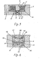
- the hydraulic control two-port valve is formed as follows; a flat cylinder with ring slot in its middle port is installed in a cup bush, each of two sealed cavities formed by the space between two ends of the flat cylinder and cup bush is respectively inst -alled a spring,so that the ring slot in the middle of flat cylinder just net overlap the four rectantular oil ports uniformlly distributed in the same section of cup bush cylindrical wall, and rectangular oil ports are just closed, each of two face to face rectangular ports are respec -tively interlinked via the slots of outer surface of cup bush,forming the inlet and outlet of the hydraulic control two-port valve.
- the hydraulic control two-port valve of present invention ( refer to Fig. 4 is constituted as follows: a flat cylinder with ring slot in its middle portion (29) is installed in a cup bush (18) and two springs (28) are installed in the two sealed cavities (30) (31) formed by the space between the two ends of the flat cylinder and cup bush, so that : the ring slot in the middle of the flat cylinder just does not overlap the four rectangular oil ports (14), (24), (25) and(26) uninformlly distributed in same section of cup bush cylindrical wall, and rectangu -lar oil ports are just closed, when the differntial pressure exists between sealed cavities, the flat cylinder will move to vary the area of four oil ports (19), (24), (25), and (20).
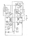
- the differential pressure of hydraulic controlled two-port valve v5 and v4 are p5 and p4 , respectively.
- the hydraulic control two- port valve v3 together with hydraulic resistor B4 constitütes a pressure amplifier.
Landscapes
- Engineering & Computer Science (AREA)
- General Engineering & Computer Science (AREA)
- Mechanical Engineering (AREA)
- Physics & Mathematics (AREA)
- Electromagnetism (AREA)
- Fluid-Pressure Circuits (AREA)
- Magnetically Actuated Valves (AREA)
- Control Of Transmission Device (AREA)
Applications Claiming Priority (2)
| Application Number | Priority Date | Filing Date | Title |
|---|---|---|---|
| CN85102444 | 1985-04-05 | ||
| CN85102444A CN85102444B (zh) | 1985-04-05 | 1985-04-05 | 集成电液控制阀 |
Publications (1)
| Publication Number | Publication Date |
|---|---|
| EP0240576A1 true EP0240576A1 (de) | 1987-10-14 |
Family
ID=4792515
Family Applications (1)
| Application Number | Title | Priority Date | Filing Date |
|---|---|---|---|
| EP19860103956 Withdrawn EP0240576A1 (de) | 1985-04-05 | 1986-03-22 | Integrierte elektro-hydraulische Einheit |
Country Status (3)
| Country | Link |
|---|---|
| EP (1) | EP0240576A1 (de) |
| JP (1) | JPS63219951A (de) |
| CN (1) | CN85102444B (de) |
Cited By (1)
| Publication number | Priority date | Publication date | Assignee | Title |
|---|---|---|---|---|
| CN108302076A (zh) * | 2018-01-30 | 2018-07-20 | 山东思达高科机械设备有限公司 | 一种利用旁路节流的电液比例伺服阀 |
Families Citing this family (2)
| Publication number | Priority date | Publication date | Assignee | Title |
|---|---|---|---|---|
| CN1304760C (zh) * | 2004-06-16 | 2007-03-14 | 陈城书 | 一种电液芯片用电液管 |
| CN101476573B (zh) * | 2009-01-06 | 2010-12-08 | 重庆跃进机械厂有限公司 | 一种集成式电液比例控制阀 |
Citations (4)
| Publication number | Priority date | Publication date | Assignee | Title |
|---|---|---|---|---|
| GB1112144A (en) * | 1965-05-12 | 1968-05-01 | Automatic Switch Co | Solenoid operated valves |
| US3416034A (en) * | 1966-04-14 | 1968-12-10 | Ite Circuit Breaker Ltd | Capacitor protection system including a plurality of serially connected valves in the air blast device |
| FR2139170A1 (de) * | 1971-05-26 | 1973-01-05 | Bosch | |
| US3970111A (en) * | 1974-09-04 | 1976-07-20 | Robert Bosch G.M.B.H. | Electromagnetic 3-way valve arrangement |
-
1985
- 1985-04-05 CN CN85102444A patent/CN85102444B/zh not_active Expired
-
1986
- 1986-03-22 EP EP19860103956 patent/EP0240576A1/de not_active Withdrawn
- 1986-04-01 JP JP7264186A patent/JPS63219951A/ja active Pending
Patent Citations (4)
| Publication number | Priority date | Publication date | Assignee | Title |
|---|---|---|---|---|
| GB1112144A (en) * | 1965-05-12 | 1968-05-01 | Automatic Switch Co | Solenoid operated valves |
| US3416034A (en) * | 1966-04-14 | 1968-12-10 | Ite Circuit Breaker Ltd | Capacitor protection system including a plurality of serially connected valves in the air blast device |
| FR2139170A1 (de) * | 1971-05-26 | 1973-01-05 | Bosch | |
| US3970111A (en) * | 1974-09-04 | 1976-07-20 | Robert Bosch G.M.B.H. | Electromagnetic 3-way valve arrangement |
Cited By (1)
| Publication number | Priority date | Publication date | Assignee | Title |
|---|---|---|---|---|
| CN108302076A (zh) * | 2018-01-30 | 2018-07-20 | 山东思达高科机械设备有限公司 | 一种利用旁路节流的电液比例伺服阀 |
Also Published As
| Publication number | Publication date |
|---|---|
| JPS63219951A (ja) | 1988-09-13 |
| CN85102444B (zh) | 1987-09-23 |
| CN85102444A (zh) | 1987-04-29 |
Similar Documents
| Publication | Publication Date | Title |
|---|---|---|
| US4585206A (en) | Proportional flow control valve | |
| US4917150A (en) | Solenoid operated pressure control valve | |
| US4311296A (en) | Cartridge element control | |
| CA2161313C (en) | Proportional variable force solenoid control valve and transmission fluid control device | |
| US4526201A (en) | Four-way valve with internal pilot | |
| US4513780A (en) | Solenoid valve | |
| US3762443A (en) | Resilient fluid control valve | |
| CN102449362B (zh) | 电磁阀 | |
| EP1211449A3 (de) | Druckwaageventil | |
| US4553732A (en) | Solenoid controlled flow valve | |
| EP0127875A2 (de) | Servoventil | |
| EP0240576A1 (de) | Integrierte elektro-hydraulische Einheit | |
| EP0434092B1 (de) | Stromregelventil | |
| CN116696878B (zh) | 一种低功耗驱动型水基比例阀先导控制阀组 | |
| JPS61127985A (ja) | バルブ装置 | |
| US3055383A (en) | Electro-hydraulic servo systems | |
| US4327627A (en) | Load responsive fluid control valve | |
| CA1173669A (en) | Flow transducer | |
| CN109578355B (zh) | 一种全桥式先导控制开关阀 | |
| US5024254A (en) | Liquid shut-off valve | |
| CN218332328U (zh) | 一种智慧方向控制阀 | |
| US2954794A (en) | Electro-hydraulic servo and inverter system | |
| US3466003A (en) | High frequency valve | |
| US2918042A (en) | Solenoid controlled fluid actuated holding device | |
| US3774642A (en) | Push-pull linear motor |
Legal Events
| Date | Code | Title | Description |
|---|---|---|---|
| PUAI | Public reference made under article 153(3) epc to a published international application that has entered the european phase |
Free format text: ORIGINAL CODE: 0009012 |
|
| AK | Designated contracting states |
Kind code of ref document: A1 Designated state(s): DE FR GB |
|
| 17P | Request for examination filed |
Effective date: 19871124 |
|
| 17Q | First examination report despatched |
Effective date: 19880929 |
|
| STAA | Information on the status of an ep patent application or granted ep patent |
Free format text: STATUS: THE APPLICATION IS DEEMED TO BE WITHDRAWN |
|
| 18D | Application deemed to be withdrawn |
Effective date: 19900109 |
|
| RIN1 | Information on inventor provided before grant (corrected) |
Inventor name: CHEN, CHENGSHU |