EP0240556B1 - Kapazitätsmessbrücke hoher genauigkeit - Google Patents
Kapazitätsmessbrücke hoher genauigkeit Download PDFInfo
- Publication number
- EP0240556B1 EP0240556B1 EP86906197A EP86906197A EP0240556B1 EP 0240556 B1 EP0240556 B1 EP 0240556B1 EP 86906197 A EP86906197 A EP 86906197A EP 86906197 A EP86906197 A EP 86906197A EP 0240556 B1 EP0240556 B1 EP 0240556B1
- Authority
- EP
- European Patent Office
- Prior art keywords
- bridge
- phase
- terminal
- summing
- ratio transformer
- Prior art date
- Legal status (The legal status is an assumption and is not a legal conclusion. Google has not performed a legal analysis and makes no representation as to the accuracy of the status listed.)
- Expired - Lifetime
Links
- 239000003990 capacitor Substances 0.000 claims abstract description 106
- 230000010363 phase shift Effects 0.000 claims description 18
- 239000007787 solid Substances 0.000 claims description 6
- 238000012935 Averaging Methods 0.000 claims description 4
- 230000008878 coupling Effects 0.000 claims description 3
- 238000010168 coupling process Methods 0.000 claims description 3
- 238000005859 coupling reaction Methods 0.000 claims description 3
- 238000000034 method Methods 0.000 abstract description 31
- 238000005259 measurement Methods 0.000 description 12
- 230000008901 benefit Effects 0.000 description 7
- 238000012937 correction Methods 0.000 description 7
- 238000010276 construction Methods 0.000 description 5
- 230000006872 improvement Effects 0.000 description 5
- 238000010586 diagram Methods 0.000 description 4
- 238000013461 design Methods 0.000 description 3
- 230000006870 function Effects 0.000 description 3
- 238000012360 testing method Methods 0.000 description 3
- 239000013598 vector Substances 0.000 description 3
- 238000011161 development Methods 0.000 description 2
- 230000008030 elimination Effects 0.000 description 2
- 238000003379 elimination reaction Methods 0.000 description 2
- 241000393496 Electra Species 0.000 description 1
- 238000013459 approach Methods 0.000 description 1
- 230000006399 behavior Effects 0.000 description 1
- 230000008859 change Effects 0.000 description 1
- 238000006243 chemical reaction Methods 0.000 description 1
- 238000004891 communication Methods 0.000 description 1
- 239000012141 concentrate Substances 0.000 description 1
- 230000001276 controlling effect Effects 0.000 description 1
- 230000000593 degrading effect Effects 0.000 description 1
- 230000000694 effects Effects 0.000 description 1
- 230000005669 field effect Effects 0.000 description 1
- 238000002847 impedance measurement Methods 0.000 description 1
- 238000010348 incorporation Methods 0.000 description 1
- 238000002955 isolation Methods 0.000 description 1
- 239000002184 metal Substances 0.000 description 1
- 238000012986 modification Methods 0.000 description 1
- 230000004048 modification Effects 0.000 description 1
- 230000003071 parasitic effect Effects 0.000 description 1
- 230000008569 process Effects 0.000 description 1
- 230000001105 regulatory effect Effects 0.000 description 1
- 239000004065 semiconductor Substances 0.000 description 1
- 230000035945 sensitivity Effects 0.000 description 1
- 239000000758 substrate Substances 0.000 description 1
- 230000002459 sustained effect Effects 0.000 description 1
- 230000009466 transformation Effects 0.000 description 1
- 238000009966 trimming Methods 0.000 description 1
Images

Classifications
-
- G—PHYSICS
- G01—MEASURING; TESTING
- G01R—MEASURING ELECTRIC VARIABLES; MEASURING MAGNETIC VARIABLES
- G01R27/00—Arrangements for measuring resistance, reactance, impedance, or electric characteristics derived therefrom
- G01R27/02—Measuring real or complex resistance, reactance, impedance, or other two-pole characteristics derived therefrom, e.g. time constant
- G01R27/26—Measuring inductance or capacitance; Measuring quality factor, e.g. by using the resonance method; Measuring loss factor; Measuring dielectric constants ; Measuring impedance or related variables
- G01R27/2605—Measuring capacitance
-
- G—PHYSICS
- G01—MEASURING; TESTING
- G01R—MEASURING ELECTRIC VARIABLES; MEASURING MAGNETIC VARIABLES
- G01R27/00—Arrangements for measuring resistance, reactance, impedance, or electric characteristics derived therefrom
- G01R27/02—Measuring real or complex resistance, reactance, impedance, or other two-pole characteristics derived therefrom, e.g. time constant
- G01R27/08—Measuring resistance by measuring both voltage and current
- G01R27/10—Measuring resistance by measuring both voltage and current using two-coil or crossed-coil instruments forming quotient
Definitions
- This invention relates to the measurement of electrical impedance, and in particular to the measurement of the loss and the very precise measurement of the capacitance of an unknown impedance where "loss" is used as a collective term to mean resistance, conductance, dissipation factor or any other term used to describe the real component of impedance.
- Tettex One manufacturer, Tettex, does make several automatic capacitance bridges which incorporate ratio transformers of which the Model 2876 is the most advanced. However, unlike the Model 1615A, these bridges use transformers where a ratio of currents is used to balance the bridge rather than a ratio of voltages as in the Model 1615A.
- the Model 2876 also uses a single external capacitance standard rather than multiple internal capacitance and resistance standards like the Model 1615A.
- the Tettex bridges are somewhat specialized in that they are designed to operate at very high voltages but are only accurate to 0.05% at best, and thus are not quite as good in this respect as the automatic impedance bridges described above.
- the bridge has a multiplying digital to analog converter driven by a voltage ratio transformer. A signal applied to a reference capacitor from the converter is balanced, using a phase detector, against the unknown impedance.
- SSRTMDACs solid state, ratio transformer driven, multiplying digital to analog converters
- the invention provides a ratio transformer bridge for balancing an unknown impedance, which bridge comprises: a first multiplying digital to analog converter for generating an in-phase output signal; a voltage ratio transformer connected to the first converter; a sinusoidal signal generator for generating a first signal for energising the transformer; reference capacitor means; first and second unknown terminals for selective connection to the unknown impedance; a phase sensitive detector circuit having a first detector terminal coupled to a second terminal of the reference capacitor means and a second detector terminal coupled to a reference terminal; CHARACTERISED BY a second multiplying digital to analog converter for generating a quadrature phase output signal; a 90° phase shifter driven by the transformer for generating a second signal for energising the second multiplying digital to analog converter, the phase of the second signal differing from the phase of the first signal by 90°; an adder for coupling the in-phase output signal and the quadrature phase output signal to a first terminal of the reference capacitor means; and a microprocessor controlling the first and second converter
- An improvement to the conventional bridge replaces the standard resistors and capacitors having lesser significance along with their associated switches with solid state multiplying digital to analog converters (hereinafter referred to as a SSMDAC, as opposed to the SSRTMDAC defined earlier). Relays are only used with the most significant standard resistors and capacitors (i.e. largest capacitors and smallest resistors) due to their low contact resistance and high isolation voltage. This arrangement has not been used in a high precision bridge before, although it has been used in some automatic capacitance bridges such as the GenRad 1680-A and the Tettex 2876.
- SSRTMDAC a special form of SSMDAC incorporating a ratio transformer which was referred to previously as a SSRTMDAC.
- This device can be constructed so as to allow its elements to be calibrated to an extremely high level of internal consistency.
- the invention in its preferred form further involves the use of reference capacitors whose values are only approximately what they should be ideally, rather than precisely what they should be. Deviations of, say, 5% offer significant economies, and allow the construction of such reference capacitors to optimize characteristics such as stability which are more important than accuracy.
- a microprocessor can be used to correct for inaccuracies in the reference capacitors and can even determine an overall correction factor by comparison with an external standard capacitor.
- Another aspect of the invention relates to the use of the precise voltage ratios provided by the ratio transformer and supported by the microprocessor to correct for errors in the ratios of the values of the internal reference capacitors and in the elements of the SSRTMDAC's.
- the preferred version of the invention provides for the elimination of the resistance standards altogether in favor of a 90° phase shifter acting in conjunction with one of the SSRTMDAC's and an existing capacitance standard. This feature effectively substitutes a more perfect capacitance standard for the relatively noisy and less pure resistance standard. This may not improve the precision of the measurement of loss beyond what other techniques can provide, but it does prevent the noise and parasitics of a resistance standard from degrading the capacitance measurements.
- a further feature of the preferred form of the invention provides means by which the 90° phase shifters noted above can be accurately adjusted to a gain of one and a phase shift of 90°. This is important in a precision bridge since phase shifters are not inherently precision circuits.
- the preferred embodiment of the invention involves the addition of some switching which allows the two SSRTMDAC's to selectively drive one of several standard capacitors in a "sliding" arrangement. This is largely an economy measure which allows a SSRTMDAC of limited range to balance the bridge over a larger range of values than would otherwise be possible. However, it works very effectively in conjunction with the quadrature SSRTMDAC to cover a wide range of losses.
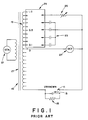
- Figure 1 is a schematic diagram of a ratio transformer bridge according to a prior art.
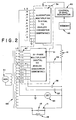
- Figure 2 is a schematic diagram of a ratio transformer bridge.
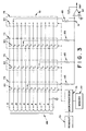
- Figure 3 shows schematically a SSRTMDAC as incorporated in the bridge of Figure 2.
- Figure 4 is a schematic diagram of a ratio transformer bridge according to the invention, this bridge incorporating a phase shifter.
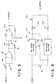
- FIGS 5 and 6 are embodiments of phase shifters pursuant to an aspect of the invention.
- Figure 7 is a schematic diagram of another ratio transformer bridge according to the invention.
- FIG. 1 shows a prior art ratio transformer impedance bridge 10 designed to measure an unknown impedance 11 composed of a capacitance 13 and a loss 15.
- the bridge includes a voltage ratio transformer 17 which is constructed to provide very precise voltage ratios in proportion to the number of turns between its taps 19. This voltage ratio transformer (as opposed to a current ratio transformer) is also referred to herein as a "ratio transformer".
- the bridge is excited by a sinusoidal signal generator 21.
- the unknown impedance 11 is balanced against a set of known reference capacitors 23 and reference resistor(s) 25.
- a null voltage detector 27 is used to detect when the bridge is in a balanced state.
- An array of switches 29 is used to connect the appropriate standard capacitors 23 and standard resistors 25 to the appropriate taps 19 to achieve balance.
- the taps are shown in a decade configuration although any number base or combination thereof may be used.
- This bridge is a good example of the basic state of a prior art in high precision capacitance bridges such as the GenRad 1615A where the switch array 29 is controlled manually.
- a similar switch array is controlled by a microprocessor.
- FIG. 2 shows a ratio transformer bridge which is an improvement over the circuit of Figure 1 where the many standard capacitors 23 of Figure 1 have been replaced with only three such capacitors 33, 35, and 37. All but these three standard capacitors are replaced by a multiplying digital-to-analog converter (SSMDAC) 31 which drives a single standard capacitor 33.
- SSMDAC multiplying digital-to-analog converter
- This converter will be referred to as the in-phase SSMDAC (or SSRTMDAC).
- SSRTMDAC in-phase SSMDAC
- the remaining two fixed standard capacitors 35, 37 balance the two most significant decades of the unknown capacitance 13 and must use relay switching elements as in Figure 1 to give these two decades the greatest possible precision.
- the variable standard resistor(s) 25 are replaced with a second SSMDAC 39 which drives a single standard resistor 41.
- This SSMDAC will be referred to as the quadrature SSMDAC (or SSRTMDAC).
- SSRTMDAC quadrature SSMDAC
- Other components of the bridge of Figure 2 include a control 43 and a memory 45 which are described below, a switch array 47 similar to array 29, a ratio tranformer 49 like ratio transformer 17, a generator 51 like generator 21, and a detector 53 like detector 27 shown in Figure 1.
- SSRTMDAC Construction of the SSMDAC's can take many forms, but a preferred unit is described herein and labeled "SSRTMDAC" and is shown in Figure 3.
- the SSRTMDAC is identified by the reference numeral 61, and includes sets of switching elements 63 which are non-mechanical, preferably solid state switches, precision resistors 65 connected to switching elements 63 and an operational or summing amplifier 67. These components form a digital to analog converter having a ratio transformer 69 and a summing point 71.
- the precision resistors 65 and summing amplifier 67 form a summing circuit.
- Each of the precision resistors 65 has replaced one of the original standard capacitors 23.
- the resistors drive the summing point 71 of operational amplifier 67 much the way that the standard capacitors drove the summing point of the bridge in Figure 1.
- the switching elements 63 are typically field effect transistors which are used for their speed, reliability and low cost. These switches may be incorporated into integrated circuit multiplexers 73 which also contain decoding and driving logic for the switches. The multiplexers select which tap of the ratio transformer 69 the resistors 65 are driven by.
- the multiplexers 73 are operated by a microprocessor 75 which controls the functions of the bridge. Microprocessor 75 operates in conjunction with a memory 77 and a readout 79 in a known manner. The net result is that the AC voltage at the output of the operational amplifier 67 can be set to any value with four decade resolution by the microprocessor.
- the SSRTMDAC example presented here is chosen so that each resistor 65 covers a single decade, but any number base or combination thereof may be used.
- the advantage associated with using a ratio transformer as a part of a SSMDAC goes beyond that of providing more precise voltages for the summing amplifier 67 to select.
- the additional advantage lies in being able to precisely calibrate the entire SSRTMDAC. This will be discussed in detail later.
- the SSRTMDAC's eliminate the need for all but the largest standard capacitors by using precision resistors and other common circuit elements. This reduces the cost of the bridge and greatly increases its speed and reliability without sacrificing the precision of the instrument.
- Figures 1 and 2 have shown two different ratio transformer bridges which can be used to measure capacitance.
- the unknown capacitance is found by balancing it against a known standard capacitance.
- the conventional practice is to identify an unknown loss by balancing it against a known resistance in some way.
- Both Figures 1 and 2 show a standard resistance 25, 41 which is used for this purpose.
- a ratio transformer bridge 81 which includes a ratio transformer 83, a generator 85, a set of taps 87, a quadrature SSRTMDAC 89, an in-phase SSRTMDAC 91, a set of relay switches 93, and a phase sensitive detector 95, all as discussed with regard to the circuitry of the preceding figures.
- a 90° phase shifter 97 with unity gain is driven from a tap on the in-phase ratio transformer 83 and drives, through a switch 98, the quadrature ratio transformer 99 having taps 100 which are associated with SSRTMDAC 89.
- Both SSRTMDAC's are regulated by a control signal generator 101 which operates under the influence of a memory 103 and which transmits output signals to a readout 105.
- the outputs of SSRTMDAC 89 and of SSRTMDAC 91 are connected to an adder 107.
- the output of adder 107 is connected to a reference capacitor 109.
- Reference capacitors 111 and 113 are adjustably connected to in-phase tranformer taps 100 via relay switches 93.
- the known capacitor In order to balance a given unknown resistance 15 by using a known capacitance, the known capacitor must have a capacitance equal to the reciprocal of the corresponding known resistor times the frequency, times 2 ⁇ as is well known. With the capacitor chosen to be this value, the only difference between it and the known resistor is that the capacitor has shifted the phase by 90° and the resistor has not. Thus by adding a precise, unity gain, 90° phase shifter 97 of the opposite sign, the phase shift introduced by the standard capacitor 107 is cancelled and the combination of the two circuit elements behaves like a resistor.
- the accuracy with which the resistive component of the unknown impedance (loss) can be measured is limited largely by the quality of the 90° phase shifter. Any error in the phase angle or the gain of the phase shifter will appear as an error in the capacitance and loss measurements.
- Phase shifter 121 has two RC networks which each use a capacitance 123 and a resistance 125 with gain provided by amplifiers 127 and 129. If the component values are chosen properly, this circuit will do an excellent job of shifting the phase by 90° while maintaining a unity gain. However, the quality of the result depends directly on the tolerance of the resistors and capacitors that are used. While it is possible, but expensive, to buy close-tolerance resistors, it is not practical to do as well with capacitors, since we are trying to achieve overall phase and gain errors of better than one part in ten thousand.
- FIG. 6 shows a phase shift circuit 131 which comprises 90° phase shifters 133, 135 whose outputs are connected respectively to resistors 137 and 139, and which are connectable through various lines through switches 141, 143 and 145.
- This circuit can be configured in two ways which we shall call “series” and "parallel".
- the parallel configuration occurs when switches 141 and 143 are closed and 145 is open.
- the series configuration has 145 closed and 141 and 143 open.
- the parallel arrangement is the normal operating configuration. It provides an average of the two 90° phase shifted signals at its output and in so doing, can provide much more precise phase shifts than either phase shifter 133, 135 individually when calibrated with the series arrangement.
- the series arrangement is used to calibrate the overall circuit in such a way that the parallel configuration produces an accurate 90° phase shift.
- the signal at the output of the two 90 degree phase shifters 133, 135 in the series configuration is nominally the inversion of the input signal.
- the output signal will be exactly the inversion of the input.
- the some kind of adjustment means is provided in one (or both) of the basic phase shifters so as to provide a way of adjusting the gain and phase of these circuits.
- the calibration method described above assumes that the error correction adjustments are made by some kind of trimmers that are built into the hardware of the circuit. These trimmers may be variable resistors which can be adjusted by hand. If such trimmers are actually digital-to-analog converters (DAC's), then the microprocessor 101 could automatically perform the calibration as often as is necessary. Unfortunately, there is a cost penalty associated with using DAC's so that a method of direct software correction could be much more cost effective. Such a method is decribed below.
- the basic phase shifters have each been set at the factory to be as close to 90° and unity gain as is practical.
- the gain of one of the basic phase shifters is 1+B and its phase shift is ⁇ /2+Q radians and that for the other phase shifter, the values are 1+C and ⁇ /2+R radians, respectively.
- the gain errors are B and C
- the phase errors are Q and R.
- phase shifters are put in the series configuration, then using algebra, one finds that the in-phase component of the output voltage is 1+B+C+BC-Q2/2-R2/2-QR to second order or simply 1+B+C to first order.
- the quadrature component of the output voltage is Q+R+BQ+BR+CQ+CR to second order or simply Q+R to first order.
- phase shifters are put in the parallel configuration, then using algebra, one finds that the in-phase component of the output voltage is (Q+R+BQ+CR)/2 to second order or simply (Q+R)/2 to first order. Similarly, the quadrature component of the output voltage is 1+(B+C)/2-Q2/4-R2/4 to second order or simply (B+C)/2 to first order.
- the phase sensitive detector 95 can be used to directly measure the in-phase and quadrature components of the output of the collective phase shifter circuitry.
- ADC analog-to-digital converter
- any deviation from zero represents the two error components, which, from our calculation above are B+C+BC-Q2/2-R2/2-QR for the in-phase part and Q+R+BQ+BR+CQ+CR for the quadrature part.
- the microprocessor saves these two numbers and uses them to correct the deviations from unity gain and 90° phase shift in the parallel configuration of the phase shifter circuitry.
- the actual correction is performed (using the microprocessor) by applying the saved error deviations to each component of the voltage read from the ADC when measuring an unknown impedance.
- the saved in-phase error deviation is divided by 2 and subtracted from the quadrature component of the unknown impedance.
- the saved quadrature error deviation is divided by 2 and subtracted from the in-phase component of the unknown impedance.
- the residual error in the unknown impedance is (BR+CQ)/2 for the in-phase component and (QR-BC)/2 for the quadrature component. Both of these are second order terms so that if the initial errors in the gain and phase shift are small, then the corrected errors will be very small. If the initial errors are of the order of 1% then the corrected errors will be of the order of 0.01%. Notice that the algebraic terms for these errors simplify to precisely the same terms as were obtained for the hardware series/parallel correction technique.
- the averaging circuit which is a part of the parallel circuit is that it need not be as precise as the phase shifted signal that it is intended to handle.
- the individual phase shifters produce voltages of V(1+ ⁇ ) and V(1- ⁇ ) and that the resistors used in the averaging circuit have a value and tolerance of R(1 ⁇ ) .
- the worst case output voltage becomes V(1+2 ⁇ ) if ⁇ 1.
- the worst case error in the amplitude of the output signal is 0.02% (.0002) which is far better than the error of ⁇ .
- each of the individual phase shifters 133, 135 must be adjusted so that the errors in the gain and phase of each are, roughly, less than the square root of the desired error level at the output of the parallel circuit 97.
- One of the easiest ways to do this is to compare the gains and phases of the two individual phase shifters 133, 135 with each other and then adjust them so that the differences between the phase shifters is zero. This will make the two phase shifters equal and in combination with the series adjustment method, will cause them each to have a gain of one and a phase shift of 90 degrees.
- phase sensitive ADC phase sensitive ADC
- T1 and T2 are explicit taps on the ratio transformer each representing only a single decade of ratio.
- T3 and T4 each represent multiple decades of transformer taps synthesized by a SSRTMDAC.
- T3 is the value for the in-phase SSRTMDAC and T4 is the value for the quadrature SSRTMDAC.
- the j indicates that the signal phase is shifted by 90° for the quadrature SSRTMDAC.
- C1 has been limited to being roughly ten times C2 and C2 must be roughly ten times C3, there are several other restrictions that must be placed upon the values of the inaccurate but stable reference capacitors if they are to function properly in a precision bridge. Since the references are expected to be of good quality, all of the R's will be very large making the first three terms of equation 3 and the fourth term of equation 4 very small. This makes the determination of the unknown capacitance in equation 4 independent of frequency to the extent that the resistance, R3, of reference C3 is large. This is desirable in a bridge designed to measure capacitance to very high precision since it eliminates the need to know the frequency precisely.
- the second restriction on the actual values that the reference capacitors may have is needed to ensure that the range of unknown values that the bridge can measure does not contain gaps where the bridge cannot balance the unknown impedance. This can occur if the transformer voltage sections or increments are too large relative to the ratio of the values of adjacent capacitance reference decades. More specifically, given the worst case tolerances for the reference capacitors, the voltage contribution of the nth reference capacitor when driven by only a single (smallest) voltage section from the ratio transformer, must be less than or equal to the sum of the contributions of all the lesser reference capacitors when driven by the highest available transformer voltage.
- N 10 and the lower bound for f/F is approximately 9/10. This is equivalent to allowing the references to deviate from their nominal value by about 5%. (Actually, conventional ratio transformer bridges may have more than ten taps, but they have never been used in this manner to compensate for very inaccurate capacitance standards.)
- the transformer taps 87, 100 which are selectable by the SSRTMDAC's range in voltage from -0.1 to +1.0. This range goes beyond what is needed to balance an unknown impedance. For that, the taps need only cover the range from 0.0 to 0.9 or 1.0.
- the addition of the -0.1 and +1.0 taps allows the ratio transformers to be used to compare adjacent balancing decades of the bridge with one another.
- the largest reference capacitor 113 which balances the highest decade of capacitance can serve as a reference standard against which all of the smaller reference capacitors and decades of the SSRTMDAC's can be calibrated. It is the extremely high accuracy that can be obtained for the voltage ratios of the transformers that make this method of calibration so attractive. Ten to one ratios with an accuracy of one ppm are easily achieved.
- capacitor 113 is connected to the -0.1 tap and capacitor 111 is connected to the 1.0 tap.
- the two SSRTMDAC's 89, 91 must be set to zero and no unknown impedance can be connected. Since C1 is nominally 10 times C2 and since precisely 10 times as much voltage of the opposite polarity is applied to C2 as to C1, the two voltage components measured at the phase sensitive detector 95 will be approximately zero. If this were done on a GenRad 1615A bridge, the calibration would be performed by adjusting the trimmer capacitor associated with the C2 standard capacitor so as to get the minimum voltage at the detector. No provision is made to adjust for any loss in the 1615A bridge's standard capacitors. This manual adjustment of the capacitance error only, or small software compensations of less than 100 ppm represents the limit of the prior state of the art. Compensation for gross deviations of the reference capacitors from their nominal values on the order of several percent is now.
- the value of the in-phase error voltage seen by the detector can be saved by the microprocessor as a measure of the capacitance error in capacitor 111 relative to capacitor 113.
- the value of the quadrature error voltage seen by the detector can be saved by the microprocessor as a measure of the loss error in capacitor 111 relative to capacitor 113.
- the in-phase and/or quadrature SSRTMDAC's can be set to cancel the error voltage to a level such that the remainder falls within the range of the ADC.
- the in-phase correction value that the microprocessor stores is then a combination of the in-phase SSRTMDAC setting and the in-phase component of the ADC.
- the quadrature value is handled in the same manner.
- Figure 4 shows switch 98 which allows the loss SSRTMDAC 89 to be switched from its normal phase shifted mode of operation to a test mode which operates at the same phase as the in-phase SSRTMDAC 91.
- the loss SSRTMDAC is in test mode, its behavior is indistinguishable from that of the in-phase SSRTMDAC and hence calibration values for it can be obtained in precisely the same manner as for the in-phase SSRTMDAC.
- the ultimate limitation on the precision with which the capacitance portion of the unknown impedance can be measured is determined by the quality of the ratio transformer and the reference capacitors.
- the basic nature of these components is such that capacitance measurements can easily be made to a precision of roughly one ppm and with difficulty to several parts per hundred million.
- the loss portion of the unknown impedance can be measured to a precision of roughly one part in ten thousand.
- the limiting factor here is the precision of the 90° phase shifter 97.
- the latter is composed of ordinary semiconductors, resistors and capacitors and thus tends to be limited to their inherent precision.
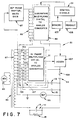
- phase shifter Since the phase shifter is such a limitation, it does not make sense economically to construct more decades of precision into the quadrature SSRTMDAC 89 than exist in the phase shifter. Instead, it is preferable to allow the sum of both SSRTMDAC's to be connected in a sliding manner to the standard capacitors as shown in Figure 7. This allows the quadrature circuitry to cover a range of loss that is as wide as the capacitance range without providing more resolution than is meaningful.
- FIG. 7 illustrates a ratio transformer bridge 151 which is similar to bridge 81 of Figure 4; therefore, like components of bridge 151 have been ascribed the reference numerals of their counterparts in Figure 4.
- Bridge 151 has a bank relay switch 153 which replaces relays 93.
- Bank relay switch 153 is identical to relays 93 except for being drawn to explicitly show the two decades of contacts and for having additional contacts 155, 157, one for each decade. These contacts 155, 157 along with switch 159 allow the output of the adder 107 to be switched to any one of the three reference capacitors 115, 113, 111.
- the in-phase SSRTMDAC goes through the adder 107, it is effectively tied to the quadrature SSRTMDAC 89 and slides with it.
- the range of capacitance is not affected, because the reference capacitors at and above the current sliding position are always available for use.
- the resolution of the capacitance does decrease as the adder slides up to larger reference capacitors.
- the capacitance and loss resolutions are the same.
Landscapes
- Physics & Mathematics (AREA)
- General Physics & Mathematics (AREA)
- Measurement Of Resistance Or Impedance (AREA)
- Measuring Instrument Details And Bridges, And Automatic Balancing Devices (AREA)
Claims (15)
- Verhältnistransformatorbrücke (81) zum Abgleich einer unbekannten Impedanz (11), wobei die Brücke folgendes aufweist:
einen ersten multiplizierenden Digital-Analog-Wandler (91) zum Erzeugen eines Ausgangssignals in Phase;
einen Spannungsverhältnistransformator (83), der mit dem ersten Wandler (91) verbunden ist;
einen Sinussignalgenerator (85) zum Erzeugen eines ersten Signals, um den Transformator (83) mit Energie zu versorgen bzw. zu erregen;
Referenz- bzw. Bezugskondensatormittel (109); erste und zweite "unbekannte" Anschlüsse zum wahlweisen Verbinden mit der unbekannten Impedanz (11), eine phasenempfindliche Detektorschaltung (95), die einen ersten Detektoranschluß besitzt, der mit einem zweiten Anschluß der Bezugskondensatormittel (109) gekoppelt ist, sowie einen zweiten Detektoranschluß besitzt, der mit einem Referenz- bzw. Bezugsanschluß gekoppelt ist;
gekennzeichnet durch einen zweiten multiplizierenden Digital-Analog-Wandler (89) zum Erzeugen eines Quadratur-Phasen- oder um 90° phasenverschobenen Ausgangssignals;
einen 90°-Phasenschieber (97), der von dem Transformator (83) betrieben wird, zum Erzeugen eines zweiten Signals zum Versorgen des zweiten multiplizierenden Digital-Analog-Wandlers (89) mit Energie bzw. zum Erregen davon, wobei die Phase des zweiten Signals sich von der Phase des ersten Signals um 90° unterscheidet;
einen Addierer (107) zum Koppeln des sich in Phase befindlichen Ausgangssignals und des Quadratur-Phasen- oder um 90° phasenverschobenenen Ausgangssignals mit einem ersten Anschluß der Bezugskondensatormittel (109); und
einen Mikroprozessor (75), der die ersten und zweiten Wandler (91, 89) zum Abgleich der Brücke (81) steuert. - Verhältnistransformatorbrücke (81) gemäß Anspruch 1, wobei der Verhältnistransformator (83) folgendes aufweist:
eine Vielzahl von Anschlüssen und den Referenz- bzw. Bezugsanschluß;
eine Summierschaltung (65, 67) mit einer Vielzahl von Summiereingangsanschlüssen und einem Summierausgangsanschluß, wobei die Summierschaltung (65, 67) eine festgelegte diskrete Verstärkung in einem im wesentlichen geordneten bzw. größenordnungsmäßig gestaffelten Verstärkungsbereich zwischen jedem der Summiereingangsanschlüsse und dem Summierausgangsanschluß vorsieht; und
Schaltelementmittel (63) zum selektiven und individuellen Verbinden der Summiereingangsanschlüsse mit der Vielzahl von Transformatoranschlüssen und dem Bezugsanschluß. - Verhältnistransformatorbrücke (81) gemäß Anspruch 2, wobei die Vielzahl der Transformatoranschlüsse folgendes aufweist:
eine Vielzahl von geordneten bzw. nach Größenordnungen sortierten oder gestaffelten positiven Anschlüssen, die Signale einer ersten Polarität bezüglich des Bezugsanschlusses liefern, und mindestens einen negativen Anchluß, der Signale einer der ersten Polarität entgegengesetzten Polarität liefert; und
wobei die Summierschaltung (65, 67) einen Summierpunktanschluß (71) und eine entsprechende Vielzahl von Widerständen (65) besitzt, die jeweils zwischen die Summiereingangsanschlüsse und den Summierpunktanschluß (71) geschaltet oder gekoppelt sind. - Verhältnistransformatorbrücke (81) gemäß einem der Ansprüche 1 bis 3, wobei der erste "unbekannte" Anschluß wahlweise mit einem negativen Anschluß des Transformators (83) verbunden ist und wobei der zweite "unbekannte" Anschluß mit dem ersten Detektoranschluß gekoppelt ist.
- Verhältnistransformatorbrücke (81) gemäß einem der Ansprüche 1 bis 4, wobei der 90°-Phasenschieber (97) folgendes aufweist:
erste und zweite 90°-Phasenverschiebungsschaltungen (133, 135); und
Reihen-/Parallel-Schaltmittel (141, 143, 145) zum wahlweisen Verbinden der ersten und zweiten 90°-Phasenverschiebungsschaltungen (133, 135) in Reihe miteinander oder parallel zueinander. - Verhältnistransformatorbrücke (81) gemäß Anspruch 5, wobei die Detektorschaltung (95) anzeigt, ob die Summe der Phasenverschiebungen der in Reihe geschalteten ersten und zweiten Phasenverschiebungsschaltungen (133, 135) gleich 180° ist, und ob das Produkt der Verstärkungen der in Reihe geschalteten ersten und zweiten Phasenverschiebungsschaltungen (133, 135) gleich einem vorbestimmten Wert ist.
- Verhältnistransformatorbrücke (81) gemäß Anspruch 6, wobei ferner folgendes vorgesehen ist:
die Detektorschaltung (95) zum Messen jeglicher Abweichung der Summe der Phasenverschiebungen von 180° und jeglicher Abweichung des Produkts der Verstärkungen von dem vorbestimmten Wert;
Mittel (103) zum Speichern der gemessenen Abweichung; und
Mikroprozessormittel (101), die auf die gemessene Abweichung ansprechen zum Berechnen des Wertes der unbekannten Impedanz (11). - Verhältnistransformatorbrücke (81) gemäß Anspruch 6 oder 7, wobei ferner folgendes vorgesehen ist:
Mittel zum Einstellen der Phasenverschiebung und der Verstärkung von mindestens einer der ersten und zweiten 90°-Phasenverschiebungschaltungen (133, 135). - Verhältnistransformatorbrücke (81) gemäß einem der Ansprüche 5 bis 8, wobei die parallel geschalteten ersten und zweiten Phasenverschiebungsschaltungen (133, 135) ferner eine durchschnittsbestimmende bzw. Mittelungsschaltung aufweisen zum Erzeugen eines Durchsschnitts bzw. Mittels der Ausgabegrößen der Phasenverschiebungsschaltungen (133, 135).
- Verhältnistransformatorbrücke (81) gemäß einem der Ansprüche 5 bis 9, wobei die unbekannte Impedanz (11) eine (Ohm'sche) Widerstandskomponente (15) umfaßt, wobei ferner Mittel vorgesehen sind zum Einstellen der Amplitude des Signals, das durch die erste und zweite 90°-Phasenverschiebungsschaltung (133, 135) und die Bezugskondensatormittel (109) gemeinsam erzeugt wird, um ein Signal zu erzeugen, das ein Signal von der Widerstandskomponente (15) der unbekannten Impedanz (11) abgleicht.
- Verhältnistransformatorbrucke (81) gemäß einem der vorhergehenden Ansprüche, wobei die Bezugskondensatormittel (109) einen Satz von Bezugskondensatoren (111, 113, 115) und Schiebeschaltmittel (155, 157, 159) aufweist zum Koppeln des Ausgangs des Addierers (107) mit einem oder mehreren der Bezugskondensatoren (111, 113, 115) aus dem Satz.
- Verhältnistransformatorbrücke (81) gemäß einem der vorhergehenden Ansprüche, wobei ferner folgendes vorgesehen ist:
die Detektorschaltung (95) zum Messen von Betriebsparametern der ersten und zweiten Wandler (91, 89);
die Mittel (103) zum Speichern von Daten oder Kennzeichen oder Indizien, die repräsentativ sind für die gemessenen Parameter; und
die Mikroprozessormittel (101), die auf die gespeicherten Daten (Kennzeichen, Indizien) ansprechen zum Berechnen des Wertes der unbekannten Impedanz (11). - Verhältnistransformatorbrücke (81) gemäß Anspruch 12, wenn abhängig von Anspruch 3, wobei die Brücke ferner Speichermittel aufweist und wobei Betriebsparameter zwischen einem der Summiereingangsanschlüsse und dem Summierausgangsanschluß genau definiert sind durch Daten, die in den Speichermitteln gespeichert sind; und
wobei die Mittel zum selektiven Messen von Betriebsparametern der ersten und zweiten Wandler (91, 89) die Betriebsparameter zwischen einem anderen der Summiereingangsanschlüsse und dem Summierausgangsanschluß messen, und zwar mit Bezug auf die Betriebsparameter zwischen dem einen Summiereingangsanschluß und dem Summierausgangsanschluß. - Verhältnisstransformatorbrücke (81) gemäß Anspruch 12, wenn abhängig von Anspruch 3, wobei die Mittel zum Messen von Betriebsparametern der ersten und zweiten Wandler (91, 89) die Schaltelementmittel (153) steuern, um,
wahlweise einen Summiereingangsanschluß mit einem der Verhältnistransformatoranschlüsse mit einer ersten Polarität zu verbinden;
wahlweise einen weiteren der Summiereingangsanschlüsse mit einem Anschluß des Verhältnistransformators mit entgegengesetzter Polarität zu verbinden, um das Eingangssignal an den Detektor (95) zu vermindern oder verkleinern; und
wahlweise andere der Summiereingangsschlüsse mit Anschlüssen des Transformators (83) zu verbinden, um das Eingangssignal an den Detektor (95) weiter zu vermindern oder verkleinern. - Verhältnistransformatorbrücke (81) gemäß einem der vorhergehenden Ansprüche, wobei mindestens einer der ersten und zweiten Wandler (91, 89) ein multiplizierender Digital-Analog-Wandler der Festkörperbauart ist.
Applications Claiming Priority (2)
| Application Number | Priority Date | Filing Date | Title |
|---|---|---|---|
| US782484 | 1985-10-01 | ||
| US06/782,484 US4772844A (en) | 1985-10-01 | 1985-10-01 | High precision capacitance bridge |
Publications (3)
| Publication Number | Publication Date |
|---|---|
| EP0240556A1 EP0240556A1 (de) | 1987-10-14 |
| EP0240556A4 EP0240556A4 (de) | 1989-10-27 |
| EP0240556B1 true EP0240556B1 (de) | 1994-02-09 |
Family
ID=25126199
Family Applications (1)
| Application Number | Title | Priority Date | Filing Date |
|---|---|---|---|
| EP86906197A Expired - Lifetime EP0240556B1 (de) | 1985-10-01 | 1986-10-01 | Kapazitätsmessbrücke hoher genauigkeit |
Country Status (5)
| Country | Link |
|---|---|
| US (1) | US4772844A (de) |
| EP (1) | EP0240556B1 (de) |
| JP (1) | JPS63501979A (de) |
| DE (1) | DE3689632T2 (de) |
| WO (1) | WO1987002142A1 (de) |
Families Citing this family (18)
| Publication number | Priority date | Publication date | Assignee | Title |
|---|---|---|---|---|
| JP2685748B2 (ja) * | 1986-07-11 | 1997-12-03 | 日本ヒューレット・パッカード株式会社 | 回路定数測定器 |
| US4896100A (en) * | 1988-08-30 | 1990-01-23 | Hitec Products, Inc. | Signal conditioner for capacitive transducer |
| US5113140A (en) * | 1990-06-20 | 1992-05-12 | National Research Council Of Canada | Microprocessor-controlled high-voltage capacitance bridge |
| US5287065A (en) * | 1991-10-04 | 1994-02-15 | Doble Engineering Company | Automatic bridge balancing using controllable impedance in characterizing unknown impedance |
| FR2693555B1 (fr) * | 1992-07-09 | 1994-09-09 | Onera (Off Nat Aerospatiale) | Dispositif de mesure d'impédance. |
| JP3356043B2 (ja) * | 1997-12-26 | 2002-12-09 | 三菱電機株式会社 | レーザ加工装置用距離検出器 |
| US6204673B1 (en) | 1998-12-01 | 2001-03-20 | Andeen-Hagerling, Inc. | Method and apparatus using feedback to correct the production of magnitude and phase relationships between two sinusoidal signals for use in a ratio-transformer capacitance bridge |
| JP2004184186A (ja) * | 2002-12-02 | 2004-07-02 | Agilent Technologies Japan Ltd | 容量測定システム |
| US6987391B2 (en) * | 2003-06-16 | 2006-01-17 | Andeen-Hagerling, Inc. | Apparatus for and method of synchronous rejection |
| GB2419950A (en) * | 2004-11-09 | 2006-05-10 | Sharp Kk | Capacitance measuring apparatus for LCD touch screen |
| CH699753A1 (de) * | 2008-10-16 | 2010-04-30 | Uster Technologies Ag | Vorrichtung und verfahren zum ausmessen einer kapazität. |
| US8255191B1 (en) * | 2009-04-30 | 2012-08-28 | Cadence Design Systems, Inc. | Using real value models in simulation of analog and mixed-signal systems |
| US8704537B2 (en) | 2011-09-27 | 2014-04-22 | The Board Of Trustees Of The Leland Stanford Junior University | Integrated capacitance bridge for high-resolution wide-temperature-range capacitance measurement |
| CN103487663B (zh) * | 2013-08-12 | 2015-09-09 | 中国振华(集团)新云电子元器件有限责任公司 | 一种超级电容器的电容量测试系统及其测试方法 |
| CN108828322B (zh) * | 2018-05-09 | 2024-02-06 | 江苏电子信息职业学院 | 一种小容量电容高速检测电路 |
| GB202001429D0 (en) | 2020-02-03 | 2020-03-18 | Razorbill Instruments Ltd | A displacement sensor |
| CN113466563B (zh) * | 2021-07-30 | 2024-08-30 | 深圳市汇创达科技股份有限公司 | 一种用于测试多路电阻阻值的装置 |
| CN114548133B (zh) * | 2022-03-09 | 2022-10-14 | 浙江海康科技有限公司 | 超高频rfid收发一体与收发分离复用读写系统及其自适应配置方法 |
Family Cites Families (2)
| Publication number | Priority date | Publication date | Assignee | Title |
|---|---|---|---|---|
| US3473117A (en) * | 1965-12-15 | 1969-10-14 | Hewlett Packard Yokogawa | Bridge circuit having phase shifter and nulling direction indicator |
| US3562641A (en) * | 1968-11-25 | 1971-02-09 | Gen Radio Co | Impedance-measuring transformer bridge with automatic digital balancing circuit |
-
1985
- 1985-10-01 US US06/782,484 patent/US4772844A/en not_active Expired - Lifetime
-
1986
- 1986-10-01 JP JP61505491A patent/JPS63501979A/ja active Pending
- 1986-10-01 WO PCT/US1986/002063 patent/WO1987002142A1/en not_active Ceased
- 1986-10-01 DE DE3689632T patent/DE3689632T2/de not_active Expired - Fee Related
- 1986-10-01 EP EP86906197A patent/EP0240556B1/de not_active Expired - Lifetime
Also Published As
| Publication number | Publication date |
|---|---|
| DE3689632T2 (de) | 1994-09-01 |
| US4772844A (en) | 1988-09-20 |
| EP0240556A1 (de) | 1987-10-14 |
| DE3689632D1 (de) | 1994-03-24 |
| JPS63501979A (ja) | 1988-08-04 |
| EP0240556A4 (de) | 1989-10-27 |
| WO1987002142A1 (en) | 1987-04-09 |
Similar Documents
| Publication | Publication Date | Title |
|---|---|---|
| EP0240556B1 (de) | Kapazitätsmessbrücke hoher genauigkeit | |
| US6362699B1 (en) | Temperature compensating circuit for a crystal oscillator | |
| US4550360A (en) | Circuit breaker static trip unit having automatic circuit trimming | |
| US5514958A (en) | Electrical energy meters having factory set calibration circuits therein and methods of calibrating same | |
| US5822225A (en) | Self-calibrating data processors and methods for calibrating same | |
| JPH0260986B2 (de) | ||
| JPH02155457A (ja) | 自己較正a―dおよびd―a変換器 | |
| US4857827A (en) | Electronic load for testing transformers | |
| US6204673B1 (en) | Method and apparatus using feedback to correct the production of magnitude and phase relationships between two sinusoidal signals for use in a ratio-transformer capacitance bridge | |
| US4006430A (en) | Circuit arrangement for converting a bridge unbalance into a frequency variation | |
| US6147312A (en) | Strain gage bridge circuit with sensitivity equalization and method for sensitivity equalization | |
| EP0690565B1 (de) | Differenzverstärker mit Gleichtaktsignalkorrektur | |
| US4795969A (en) | Load loss standard for testing and calibrating high voltage power measuring systems | |
| US5113140A (en) | Microprocessor-controlled high-voltage capacitance bridge | |
| Corney | Digital generator assisted impedance bridge | |
| US4278932A (en) | A.C. Bridges | |
| US3437160A (en) | Weighing system | |
| US3027511A (en) | Vector bridge | |
| JP3162307B2 (ja) | 計器用変成器負担装置 | |
| Moore et al. | Direct reading ratio-error sets for the calibration of current transformers | |
| CA1235748A (en) | Replica circuit | |
| US5051687A (en) | Transimpedance circuit | |
| US3705344A (en) | Wideband constant amplitude-variable phase circuit | |
| JPH08166414A (ja) | 抵抗器の電圧特性測定法 | |
| US3027957A (en) | Weighing system |
Legal Events
| Date | Code | Title | Description |
|---|---|---|---|
| PUAI | Public reference made under article 153(3) epc to a published international application that has entered the european phase |
Free format text: ORIGINAL CODE: 0009012 |
|
| 17P | Request for examination filed |
Effective date: 19870529 |
|
| AK | Designated contracting states |
Kind code of ref document: A1 Designated state(s): BE DE FR GB NL |
|
| A4 | Supplementary search report drawn up and despatched |
Effective date: 19891027 |
|
| 17Q | First examination report despatched |
Effective date: 19910125 |
|
| GRAA | (expected) grant |
Free format text: ORIGINAL CODE: 0009210 |
|
| AK | Designated contracting states |
Kind code of ref document: B1 Designated state(s): BE DE FR GB NL |
|
| PG25 | Lapsed in a contracting state [announced via postgrant information from national office to epo] |
Ref country code: NL Effective date: 19940209 Ref country code: FR Free format text: THE PATENT HAS BEEN ANNULLED BY A DECISION OF A NATIONAL AUTHORITY Effective date: 19940209 Ref country code: BE Effective date: 19940209 |
|
| REF | Corresponds to: |
Ref document number: 3689632 Country of ref document: DE Date of ref document: 19940324 |
|
| EN | Fr: translation not filed | ||
| NLV1 | Nl: lapsed or annulled due to failure to fulfill the requirements of art. 29p and 29m of the patents act | ||
| PLBE | No opposition filed within time limit |
Free format text: ORIGINAL CODE: 0009261 |
|
| STAA | Information on the status of an ep patent application or granted ep patent |
Free format text: STATUS: NO OPPOSITION FILED WITHIN TIME LIMIT |
|
| 26N | No opposition filed | ||
| PGFP | Annual fee paid to national office [announced via postgrant information from national office to epo] |
Ref country code: DE Payment date: 19970925 Year of fee payment: 12 |
|
| PGFP | Annual fee paid to national office [announced via postgrant information from national office to epo] |
Ref country code: GB Payment date: 19970926 Year of fee payment: 12 |
|
| PG25 | Lapsed in a contracting state [announced via postgrant information from national office to epo] |
Ref country code: GB Free format text: LAPSE BECAUSE OF NON-PAYMENT OF DUE FEES Effective date: 19981001 |
|
| GBPC | Gb: european patent ceased through non-payment of renewal fee |
Effective date: 19981001 |
|
| PG25 | Lapsed in a contracting state [announced via postgrant information from national office to epo] |
Ref country code: DE Free format text: LAPSE BECAUSE OF NON-PAYMENT OF DUE FEES Effective date: 19990803 |