EP0240099A2 - Induktionsheizungs- und -schmelzsysteme mit Induktionsspulen - Google Patents
Induktionsheizungs- und -schmelzsysteme mit Induktionsspulen Download PDFInfo
- Publication number
- EP0240099A2 EP0240099A2 EP87300345A EP87300345A EP0240099A2 EP 0240099 A2 EP0240099 A2 EP 0240099A2 EP 87300345 A EP87300345 A EP 87300345A EP 87300345 A EP87300345 A EP 87300345A EP 0240099 A2 EP0240099 A2 EP 0240099A2
- Authority
- EP
- European Patent Office
- Prior art keywords
- coil
- windings
- conductor
- current
- coils
- Prior art date
- Legal status (The legal status is an assumption and is not a legal conclusion. Google has not performed a legal analysis and makes no representation as to the accuracy of the status listed.)
- Granted
Links
Images


Classifications
-
- H—ELECTRICITY
- H05—ELECTRIC TECHNIQUES NOT OTHERWISE PROVIDED FOR
- H05B—ELECTRIC HEATING; ELECTRIC LIGHT SOURCES NOT OTHERWISE PROVIDED FOR; CIRCUIT ARRANGEMENTS FOR ELECTRIC LIGHT SOURCES, IN GENERAL
- H05B6/00—Heating by electric, magnetic or electromagnetic fields
- H05B6/02—Induction heating
- H05B6/22—Furnaces without an endless core
-
- H—ELECTRICITY
- H05—ELECTRIC TECHNIQUES NOT OTHERWISE PROVIDED FOR
- H05B—ELECTRIC HEATING; ELECTRIC LIGHT SOURCES NOT OTHERWISE PROVIDED FOR; CIRCUIT ARRANGEMENTS FOR ELECTRIC LIGHT SOURCES, IN GENERAL
- H05B6/00—Heating by electric, magnetic or electromagnetic fields
- H05B6/02—Induction heating
- H05B6/36—Coil arrangements
- H05B6/42—Cooling of coils
Definitions
- This invention relates to improvements in induction heating and melting systems and more particularly to improvements in the coils or inductors in such systems.
- induction heating has become an important technique in such applications as melting, reheating before forming and localized heat treatment. Some areas still remain, however, where induction heating has not seen the same development because of inadequate or poorly performing equipment, lack of experience, or unexpressed requirements.
- the coils or inductors in induction heating are required to produce alternating magnetic fields of very large intensities (in the range 80,000 to 300,000 amperes turns per metre).
- induction heating coils are made of hollow copper conductors, which are wound into a single layer solenoidal coil. Because the coil consists of only a single layer of rather large conductor, the number of turns must be small and therefore the current in each turn must be very high to achieve the field intensities required. This gives rise to very large I 2 R losses in the reactor and therefore the efficiency with which energy is transferred from the coil to the billet being heated is low (typically in the range of 30 to 70 percent depending upon the material being heated and the frequency being used).
- a principal object of the present invention is to provide an increase in the efficiency of induction heating systems by providing an inductor arrangement that reduces electrical losses. This is accomplished in accordance with one aspect of the present invention wherein the coil is a single or multiple layer, stranded conductor coil in which the current distribution is controlled.
- the induction heating coil conductor itself is of novel design and the arrangment is such that both throughput current losses and eddy losses may be controlled in an arbitrary way.
- the windings are connected in parallel and the current distribution to the windings can be maintained at a pre-determined value despite changes in the frequency of the coil supply, despite the changes in load introduced into the coil and in the presence of magnetic yokes surrounding the coil.
- very low coil losses may be obtained and the voltage between adjacent conductors may be reduced to a small fraction of its normal value by means of voltage grading.
- the sharing of current among the individual paralleled coils is, in a preferred embodiment, controlled by an automatic current balancing scheme which maintains the pre-determined current division automatically despite changes in the frequency of the supply to the induction heating device, despite changes' in the load inside the device, and despite the presence of yokes, if used.
- the induction heating device may or may not contain a spider type connecting bus at one end connecting the layers of coils in parallel.
- the conductors forming the individual coils preferrably are made of stranded and transposed subconductors to control eddy losses and special conductors may be used for forced air cooling or for water cooling.
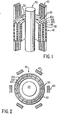
- FIG. 1 shows, in partial cross section, a part of the physical portion of an induction heating apparatus which includes an induction coil 10, provided in accordance with the present invention, with a central billet 20 to be heated thereby.
- the induction coil 10 is shown as having three coil packages designated respectively 10A, 10B and 10C but any number of packages, i.e. one or more, may be used.
- the three packages are coaxial and radially spaced and adjacent packages are separated from one another by spacers 30.
- Each package may consist of a single winding or two or more windings wound simultaneously whereby the conductors i.e. 11A, 11B, are interleaved i.e. a single layer coil. Special conductors, to be described hereinafter, are preferrably used.
- Each package can consist of one or two or more interwoven identical helical windings all having the same inside and outside diameter and the same number of turns i.e. a single layer.
- a package may also consist of two or more coaxial coil windingswound one upon the ' other providing multiple coil layers. The manner of terminating the ends of these individual helices will be discussed hereinafter.
- each package 10A, 10B, etc. is shown as containing two interwoven helices, any number of interwoven helices may be used in any layer and each package may have multiple layers.
- the billet 20 (which could be solid or liquid, non-magnetic or magnetic and an arbitrary length) is conducting and, if desired, a number of laminated magnetic steel yokes 40 can be provided to carry the return flux outside the coil to prevent this flux from inducing unwanted eddy currents in surrounding structures.
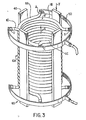
- composite coil 10 which is shown in cross section in Figure 1 and in plan view in Figure 2, comprises 6 separate, magnetically coupled coils. It is now required to connect these coils electrically in parallel in such a manner that each of the coils will carry a pre-determined share of the overall current despite the presence or absence of the billet, despite the frequency of the supply to which the coils are connected and despite the presence or absence of the yokes. This goal may be achieved by a judicious choice of the number of turns used in the various packages in conjunction with a current balancing system which will be described hereinafter.
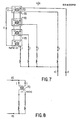
- FIG. 3 diagramatically illustrates a single layer coil, i.e. 10A, but with four interleaved windings instead of only two as illustrated in Figure 1.
- the four interleaved windings are ' designated 11A, 11B, 11C and 11D around which are symetrically situated four steel yokes 40.
- the four coil windings 11A, 11B, 11C and 11D are connected in parallel at the top end via a ring bus 50, which runs outside the yokes.
- the four coil windings 11A, 11B, 11C and 11D spiral downward in a counterclockwise direction where they terminate at different circumferential positions on the coil i.e. 90' from one another and are connected via a second bus ring 60 to an output line.
- Coil winding 11A is shown with the top end start of the winding designated as A.
- Coil windings 11B, 11C and 11D are shown with the top end start of the windings designated B, C and D respectively.
- the four interwoven coil windings thus carry counterclockwise currents together producing an upward flux in' the coil as shown schematically by the arrow X.
- This flux is captured by the four yokes which each carry one-fourth of the total flux downward as shown schematically by the arrow Y. For the moment, the leakage flux which moves downward outside or between the yokes will be ignored.
- points A, B, C and D corresponding to the beginings of the four interwoven windings, are at the same potential.
- point B' which is on the same winding as point B but a quarter turn later, is at a different potential than point B due to the induced voltage caused by the inner flux over the quarter turn distance.
- point B is at a potential which is one quarter of the voltage per turn higher than point B. Therefore, the potential difference between points A and B' is only a quarter of the turn-to-turn voltage which would result in a single layer coil occupying the same space as the four interwoven windings and containing the same number of turns as each of the interwoven windings.
- the coil layers are designed 10A, 10B, 10C...10n with the layer n representing the last in any number of layers, and, for the sake of clarity, it is assumed that there is only one helix per layer.
- the inductances shown represent the self-inductances of the individual windings comprising the overall coil and it is to be understood that all such inductances are mutually coupled.
- the coil layers have designate thereon current I, voltage V , Resistance R and inductance L with appropriate subscripts for the respective different coil layers.
- Equation 1 L kk represents a self-inductance of winding k
- Lij represents a mutual inductance between windings i and j
- Ltj represents the mutual inductance between the billet 20 and winding j
- R n represents the resistance of winding n
- Rl represents the equivalent resistance of the billet.
- ⁇ with a subscript, represents the total flux linking the subscripted winding. As may be seen in Figure 4 the bottom of all windings are connected in common.
- the required voltages may be injected into the various windings by the use of transformers 70 shown in Figure 6.
- the primaries 71 of n identical transformers are connected in series with one line L 1 as shown.
- the secondary 72 of each of the transformers is connected in series with one of the layers 10A, 10B, 10C, etc., associated therewith, the other end of the secondaries being connected in common as shown by line L 2 and the common point connected in series with the primaries.
- the turns ratio of each transformer is l:n, that is, the secondaries have n times as many turns as the primaries.
- the current in the secondary of each transformer must be exactly 1/n times the current in the primary, that is, the current in all of the windings are forced to be the same regardless of whether there was an initial imbalance or not.
- the current balance occurs because a voltage appears across the terminals of each of the secondaries which is precisely of the right magnitude and phase to make the total voltage across each winding and its transformer exactly the same as that across each of the other windings and its transformer.
- the voltages appearing on the secondaries cause voltages across the primaries of all the transformers which are smaller by exactly the transformer ratio. It is apparent that the voltages across some of the transformers will be positive and across others will be negative as required to make all winding voltages average out to the same value.
- the transformers are not ideal and the flux in the core of each transformer requires an exciting current. As is the case in all transformers this exciting current is negligibly small as long as the cores are not driven into saturation.
- the other design criteria for the transformers is that the winding have sufficient cross-section to carry the rated currents of the windings.
- Figures 7, 8 and 9 Three other embodiments of the invention are shown in Figures 7, 8 and 9.
- all of the transformers 70 have a ratio 1:1 and, as may be seen, all of the primary windings 71 are connected in series in a ring.
- This circuit behaves exactly the same as that shown in Figure 6 and has the obvious advantage that the primary and the secondary windings are identical.
- Figure 8 shows the simplest embodiment of this invention.
- a single transformer 70 is shown being used to balance the current in a two winding device.
- Figure 9 shows a scheme using n-1 transfomrers 70 to balance the currents in an n windng system. In this scheme one of the windings is chosen as the reference winding and is connected in series with all of the primaries. This has an obvious advantage over the circuits shown in Figure 6 and 7 of requiring one less transformer.
- Figure 10 shows the circuit diagram corresponding to a single layer coil, for example 10A, comprising three interleaved identical windings 11A, 11B and 11C in which the current balancing scheme (transformers 70), combined with two small series reactors 80 and 81, are used to achieve both current balancing and voltage grading among the three interleaved coils, in the presence or absence of a load, despite changes in frequency and in the presence or absence of yokes. It is assumed that the three windings begin at a common point at one end of the coil and end at a common point on the other end of the coil.
- the current balancing scheme transformers 70
- two small external reactors 80 and 81 are added in series with respective ones of two of the inerleaved coils (shown as coil 11B and 11C respectively, where coils 11B and 11C are adjacent to each other).
- the small external reactor 80 is chosen so that the voltage drop across it, when rated current flows through coil 11B, is exactly one-third of the turn voltage at the end of the winding.
- external reactor 81 is chosen so that the voltage drop across it is exactly two-thirds of the voltage per turn when coil 11C is carrying its rated current.
- the voltage drop between points a and b and between points b and c is exactly one-third of the volts per turn, assuming that all three interleaved coils are carrying the same currents.
- the current balancing scheme i.e. transformers 70, are installed at the opposite end of the coil and operates in exactly the same manner as described in the previous section.
- the current balancing system not only forces the currents to be equal in the three interleaved coils but it also ensures that the potential difference between points a l and b l and also between points b l and c 1 is exactly one-third of the volts per turn at the end of the coil.
- the current balancing system injects exactly the right voltages into the system to ensure that this happens. It follows therefore, that the potential difference between any two adjacent conductors along the length of the coil is always one-third of the volts per turn at that location and, therefore, the voltage is continusously graded along the length of the coil.
- the current balancing circuit used is only one of several possible ones as discussed in the previous section.
- a preferred embodiment of the overall induction heating system comprises a multi-layer coil in which the individual layers comprise interwoven helical windings, in which the conductors preferrably are of a special low loss kind as described hereinafter, where the overall current balance among windings in different layers is maintained by the current balancing system described above, where the current balancing among the interwoven helices of a single layer is maintained either by the current balancing system or by the novel ring bus system in conjunction with the yokes described above, and lastly, where voltage grading among interwoven helices of a single layer is provided either by the novel ring bus system described above when yokes are present or by the use of small external reactors in conjunction with the current balancing system as described above when yokes are not present.
- the coils described in the foregoing are preferably wound from low loss conductor cables some embodiments of which are illustrated in figures 11 to 17.
- Rectangular roll formed cables for the coils may be constructed from a number of circular insulated subconductors (or bunched or transposed subconductors) which are cabled in a unilay construction about a central conductor or temporary mandril and then roll formed to achieve compaction and the required rectangular shape.
- the rectangular rolled formed cables may be divided into two broad categories: (1) those in which the successive layers of round wires are wound about a central wire of the same size, and (2) those in which the layer (or layers) of round wires are wound about a central mandril which is then withdrawn.
- FIG 11 there is illustrated a composite conductor which, for example, may be coil windings 11A and/or 11B and/or 11C referred to with respect to Figure 1, formed by spiralling round conductors 91 about a central conductor 92 in a known manner by use of a winding machine. Successive layers may be spiralled, one such further layer being shown in Figure 12, the direction of spiralling being the same so that the successive layers are nested into each other.
- Figure 13 shows the composite multi-layer conductor of Figure 12 after it has been passed through a number of rollers to achieve a compacted rectangular cross section. Experience has shown that it is relatively easy to obtain rectangular shapes having aspect ratios of from one to three. The aspect ratio of a cable is the width divided by the height, i.e. w/h.
- Figure 14 shows a cable wherein a layer of circular conductors 91 have been wound without a center core wire.
- the conductors are wound around the periphery of a mandril 93 (see Fig. 15) and as they are wound, they are slid off the mandril.
- the cable of Fig. 15 is passed between press rollers so as to be formed in the flat rectangular cross section shown in Figure 16.
- press rollers so as to be formed in the flat rectangular cross section shown in Figure 16.
- FIG. 17 shows Using this method of construction, it is possible to make conductors with rectangular cross sections having aspect ratios very much greater than three.
- a variant of this type of construction is shown in Figure 17 where a second layer of conductors 91 has been spiralled around a first layer and then roll formed to compact the cable and give it a rectangular cross section.
- coreless wound cable is known as, for example, from' the teachings of United States Patent 3,828,120, issued August 6, 1974, and assigned to The Anaconda Company, it was not known or expected beneficial results could be obtained using the same in the coil winding of a reactor.
- a plurality of electrical subconductors 101 are cabled in unilaid spiral fashion over a hollow, generally circular, cross section cooling tube 102, through which a fluid or liquid coolant such as water, may be circulated.
- the subconductors 101 are generally metallic and preferably copper or aluminum.
- the thermal and electrical properties of the cooling tube 102 are critical to the proper operation of induction coil in which the cable is used. On the one hand, the thermal conductivity must be sufficiently large to transfer the 1 2 R losses and eddy losses in the strands under maximum current conditions to the fluid flowing through the cooling tube.
- the electrical conductivity must be sufficiently small to keep the eddy current losses in the cooling tube small.
- the acceptable levels of the thermal conductivities and electrical conductivities is a complex function of the conductor geometry, the coil geometry, the frequency of the current and the current density in the conductor. However, the levels can be readily established by one knowledgeable in the art. For line frequency operation of even large reactors, for example, #304 stainless steel has acceptable properties. For 10 kHz coils, Teflon has been found to work well. For intermediate frequencies composite cooling tubes, eg. glass-fibre reinforced, carbon-fibre reinforced, or, stainless steel reinforced plastic appear to be suitable.
- the subconductors 101 are electrically insulated from each other by a coating 103 and the fact that they are cabled in spiral fashion around the cooling tube 102 effectively continuously transposes them so that they share the total current equally.
- the entire assembly may be coated with an exterior coating layer 104, which acts as an insulation layer and also as a protection against physical damage or abrasion.
- Coating layer 104 may be applied by winding a filament material or by extruding an insulating thermoplastic or thermosetting material over the assembly.
- the apparatus size and/or configuration and the frequency of operation may mean that even with an arrangement of subconductors 101 as described hereinabove, the eddy losses in the subconductors are unacceptably large.
- the subconductors 101 may themselves be subdivided into smaller sub-subconductors 106 as shown in Figure 20.
- the number and size of the sub-subconductors may be selected to make the eddy current losses as low as is required, within practical limits.
- the sub-subconductors 106 may be transposed by bunch cabling or be regular cabling and then by roll forming into trapezoidal segmental shapes either before they are wound over the cooling tube 102 or while they are being wound over the cooling tube 102.
- a second layer of subconductors 107 is cabled over the first layer before the insulating material 104 is applied.
- the subconductors in both layers are insulated individually and these subconductors may be further subdivided into insulated strands, as explained above, to further reduce eddy losses.
- the cable may be made approximately rectangular in cross section as shown in figure 19(a) by winding the conductors 101 over a cooling tube 102 of rectangular cross section.
- the conductors 101 may be wound over a circular cooling tube 102 and the resulting cable roll-formed to have a rectangular cross section.
- FIG 22 A further, more complex embodiment is illustrated in Figure 22, and shows a composite cable 110 comprising seven subcables 111 each of which is fabricated as in Figures 18, 20 or 21.
- the composite cable 110 is formed by spiralliing six outer subcables, in the conventional way of making cables.
- the entire assembly may be insulated with a layer 113 of insulating material as hereinbefore described.
- the layer 104 about each of the subcables may be omitted as each of the subconductors is covered with an insulating layer and consequently layer 104 may be redundant.
- the subcables 111 may be roll formed to have a segmental cross-section.
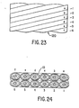
- FIG. 23 and 24 An alternative form of a composite cable such as that of Figure 22 is shown in Figure 23 and 24.
- a large flat cable 120 comprising a plurality of subcables 111 (Fig. 18) continuously transposed around the cable without the use of a central core cable, is illustrated.
- the cable 120 is roll or otherwise formed, after cabling to provide the flat shape.
- This form of continuous transposition provides an improved space factor and very low eddy losses and can be produced by cabling the subcables 91 around a mandril which is subsequently withdrawn from the composite cable.
- the coil is a single cylindrical unit with two or more coil windings interleaved. Electrically the two windings are connected in parallel. As previously mentioned, any number of coil windings can be used.
- the two windings in Fig. 1 are designated 11A and 11B in one cylindrical unit referred to as a coil layer which is designated, by way of example, 10C. Additional coil layers may be used with all such layers being coaxial and preferrably of the same axial length.
- a single coil package may consist of one or more layers with the whole package embedded in a glass reinforced resin providing rigidity to the unit.
- the coil unit, as in Fig. 1, i.e. coil packages 10A, 10B and 10C are radially spaced form one another providing an air gap AG for circulation of cooling air therethrough, the packages being spaced apart from one another by member 30.
- the coil layers 10A, 10B, 10C can be wound tightly on one another without any radial spacing between the coil packages. This provides a very rigid structure with close coupling of the coils.
- the number of turns of the coils winding are designed to balance the coils as closely as possible so as to minimize circulating currents in the parallel connected coils even in the absence of the a current balancing system. Fine tuning of the balancing and balancing under varying load conditions is effected by the previously described arrangement of balancing transformers.
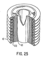
- the 1 2 R loss of the conductors in the form of heat is removed by cooling ducts in the air-cooled coils and by cooling tubes running down the centre of the special water-cooled conductors. It is also required to remove the heat flux which flows from the hot billet (or melt) out through the refractory between the billet or metal and the coil to control the thermal gradient across the refractory. In the conventional designs this heat flux is removed by the hollow copper winding conductors themselves. For small heat fluxes, the special water-cooled cables can absorb the heat without damaging the conductor 101 around the cooling tube 102. However, for large heat fluxes it is normally necessary to construct a heat sink on the outer surface of the refractory and inside the coil.
- FIG. 25 in partial cut away illustrates a heat sink winding 122 between the refractory 121 and the induction heating coil unit 10.
- the heat sink comprises a single helical coil or several interwoven helices all in a single layer but isolated from each other and from the main coil.
- the heat sink coils are wound from a hollow tube the size and material of which are chosen to give good heat transfer characteristics and to have small eddy losses e.g. from #304 stainless steel tube.
- the heat sink windings carry cooling fluid but carry no current. It is to be understood the coil unit is as described previously with respect to figs. 1 to 24 incorporating the various features, individually, in combination and in various subcombination and permutations.
- the number of turns used and the number of interwoven helices can be chosen to grade the voltage along the heat sink winding so that there is virtually no electrical stress between it and the coil windings. This can be achieved by using approximately the same number of turns and the same number of interwoven helices as are used in the innermost layer of the coil.
- Tables 1 and 2 The benefits of constructing induction heating coils according to the methods disclosed herein are illustrated by Tables 1 and 2 below.
- Table 1 describes the four coils which were built and tested: coils A and B built as single layer coils from hollow copper conductors in the conventional manner and coils AA and BB which were built for the same service but according to the methods disclosed herein.
- Both of the high efficiency coils comprised two layers of the special conductors described herein and a current balancing scheme like that shown in figure 8 which was used to insure that the currents in the two layers were equal.
- Table 2 compares the energy transfer efficiency of the conventional coils and of the replacement coils built according to this disclosure for the case where comparable coils were used at the same frequency and where they were required to deliver the same power to the billet.
- the actual energy transfer efficiency was measured at room temperature 20 * C, and the results for these tests are shown.
- the results were also extrapolated to the case of molten al at 750 * C. This was done by using a value for the resistivity of molten al of 28 x 1 0- 8 ohm meters.
- the performance of coils A and AA are compared only at the design frequency of 4 kHz while the behaviour of coils B and BB are compared both at the design frequency of 1kHz and also at 3kHz.
Landscapes
- Physics & Mathematics (AREA)
- Electromagnetism (AREA)
- General Induction Heating (AREA)
- Lining Or Joining Of Plastics Or The Like (AREA)
Priority Applications (1)
| Application Number | Priority Date | Filing Date | Title |
|---|---|---|---|
| AT87300345T ATE104494T1 (de) | 1986-01-17 | 1987-01-16 | Induktionsheizungs- und -schmelzsysteme mit induktionsspulen. |
Applications Claiming Priority (2)
| Application Number | Priority Date | Filing Date | Title |
|---|---|---|---|
| CA499813 | 1986-01-17 | ||
| CA000499813A CA1266094A (en) | 1986-01-17 | 1986-01-17 | Induction heating and melting systems having improved induction coils |
Publications (3)
| Publication Number | Publication Date |
|---|---|
| EP0240099A2 true EP0240099A2 (de) | 1987-10-07 |
| EP0240099A3 EP0240099A3 (en) | 1989-07-26 |
| EP0240099B1 EP0240099B1 (de) | 1994-04-13 |
Family
ID=4132293
Family Applications (1)
| Application Number | Title | Priority Date | Filing Date |
|---|---|---|---|
| EP87300345A Expired - Lifetime EP0240099B1 (de) | 1986-01-17 | 1987-01-16 | Induktionsheizungs- und -schmelzsysteme mit Induktionsspulen |
Country Status (9)
| Country | Link |
|---|---|
| US (1) | US4874916A (de) |
| EP (1) | EP0240099B1 (de) |
| AR (1) | AR241303A1 (de) |
| AT (1) | ATE104494T1 (de) |
| AU (1) | AU594414B2 (de) |
| BR (1) | BR8700186A (de) |
| CA (1) | CA1266094A (de) |
| DE (1) | DE3789570T2 (de) |
| NZ (1) | NZ218993A (de) |
Cited By (2)
| Publication number | Priority date | Publication date | Assignee | Title |
|---|---|---|---|---|
| US5744784A (en) * | 1994-06-13 | 1998-04-28 | Otto Junker Gmbh | Low-loss induction coil for heating and/or melting metallic materials |
| EP4093153B1 (de) | 2021-05-20 | 2023-12-06 | IAS GmbH | Vorrichtung zur induktiven erwärmung von metallgut |
Families Citing this family (47)
| Publication number | Priority date | Publication date | Assignee | Title |
|---|---|---|---|---|
| CA2008232C (en) * | 1989-01-23 | 1994-07-19 | Atsushi Iguchi | Low-frequency electromagnetic induction heater |
| EP0383272B1 (de) * | 1989-02-17 | 1993-07-21 | Nikko Corporation Ltd. | Niederfrequenz-Induktionsheizelement |
| US5025122A (en) * | 1989-11-03 | 1991-06-18 | Ajax Magnethermic Corporation | Induction heater with axially-aligned coils |
| US5197940A (en) * | 1990-01-29 | 1993-03-30 | Hypertherm Corp. | Local application tumor treatment apparatus |
| FR2663490B1 (fr) * | 1990-06-15 | 1992-09-11 | Rotelec Sa | Bobine de chauffage inductif. |
| JPH04230987A (ja) * | 1990-06-18 | 1992-08-19 | Nikko Kk | 電磁誘導加熱器 |
| US5200595A (en) * | 1991-04-12 | 1993-04-06 | Universite De Sherbrooke | High performance induction plasma torch with a water-cooled ceramic confinement tube |
| DE69111597T2 (de) * | 1991-06-05 | 1996-08-08 | Hidec Co Ltd | Wiederfrequenzinduktionsheizgerät. |
| US5569329A (en) * | 1995-06-06 | 1996-10-29 | Carbomedics, Inc. | Fluidized bed with uniform heat distribution and multiple port nozzle |
| DE19742427A1 (de) * | 1997-09-25 | 1999-04-08 | Siemens Ag | Verfahren zur Verfestigung von Wicklungsspulen elektrischer Maschinen |
| US6492890B1 (en) * | 2000-03-10 | 2002-12-10 | Koninkijlike Philips Electronics N.V. | Method and apparatus for cooling transformer coils |
| US6781100B2 (en) | 2001-06-26 | 2004-08-24 | Husky Injection Molding Systems, Ltd. | Method for inductive and resistive heating of an object |
| US6717118B2 (en) | 2001-06-26 | 2004-04-06 | Husky Injection Molding Systems, Ltd | Apparatus for inductive and resistive heating of an object |
| US7023312B1 (en) * | 2001-12-21 | 2006-04-04 | Abb Technology Ag | Integrated cooling duct for resin-encapsulated distribution transformer coils |
| US6555801B1 (en) | 2002-01-23 | 2003-04-29 | Melrose, Inc. | Induction heating coil, device and method of use |
| US6946761B2 (en) * | 2003-04-18 | 2005-09-20 | Asml Holding, N.V. | Actuator coil cooling system |
| RU2431628C2 (ru) * | 2006-08-07 | 2011-10-20 | Мессье-Бугатти | Способ уплотнения пористых изделий |
| US20100008112A1 (en) * | 2008-07-09 | 2010-01-14 | Feng Frank Z | Interphase transformer |
| WO2010138540A1 (en) * | 2009-05-26 | 2010-12-02 | Parker Hannifin Corporation | Pumped loop refrigerant system for windings of transformer |
| CN101782324B (zh) * | 2010-02-05 | 2011-09-28 | 新星化工冶金材料(深圳)有限公司 | 控制铝钛硼(碳)合金中TiB2(TiC)颗粒团平均名义直径的电磁感应熔炼电炉 |
| TWI452582B (zh) * | 2010-02-23 | 2014-09-11 | Pulse Electronics Corp | 編織導線、感應裝置及製造其之方法 |
| CN102456475A (zh) * | 2010-10-19 | 2012-05-16 | 通用电气公司 | 磁性元件 |
| EP2695484B1 (de) * | 2011-04-05 | 2015-10-14 | Comaintel, Inc. | Induktionserhitzungs-arbeitsspule |
| KR101803102B1 (ko) * | 2011-07-05 | 2017-11-29 | 김두리 | 자가발전장치 결합체 및 이를 이용한 발전시스템 |
| DE102011082045A1 (de) * | 2011-09-02 | 2013-03-07 | Schmidhauser Ag | Drossel und zugehöriges Herstellungsverfahren |
| US9330836B2 (en) * | 2012-01-10 | 2016-05-03 | Samsung Electronics Co., Ltd. | Self-resonant apparatus for wireless power transmission system |
| US10462855B2 (en) * | 2012-03-01 | 2019-10-29 | Inova Lab S.R.L. | Device for induction heating of a billet |
| US10840005B2 (en) | 2013-01-25 | 2020-11-17 | Vishay Dale Electronics, Llc | Low profile high current composite transformer |
| US10645763B2 (en) | 2013-02-19 | 2020-05-05 | Illinois Tool Works Inc. | Induction heating head |
| US10034330B2 (en) * | 2013-03-15 | 2018-07-24 | National Oilwell Varco, L.P. | System and method for heat treating a tubular |
| ITTO20130430A1 (it) | 2013-05-28 | 2014-11-29 | Illinois Tool Works | Dispositivo per il pre-riscaldamento ad induzione e la saldatura testa a testa di lembi adiacenti di almeno un elemento da saldare |
| DE102013211563A1 (de) * | 2013-06-19 | 2014-12-24 | Behr-Hella Thermocontrol Gmbh | Heizvorrichtung |
| US9913320B2 (en) | 2014-05-16 | 2018-03-06 | Illinois Tool Works Inc. | Induction heating system travel sensor assembly |
| US11510290B2 (en) | 2014-05-16 | 2022-11-22 | Illinois Tool Works Inc. | Induction heating system |
| US10863591B2 (en) | 2014-05-16 | 2020-12-08 | Illinois Tool Works Inc. | Induction heating stand assembly |
| US11076454B2 (en) | 2014-05-16 | 2021-07-27 | Illinois Tool Works Inc. | Induction heating system temperature sensor assembly |
| US11197350B2 (en) | 2014-05-16 | 2021-12-07 | Illinois Tool Works Inc. | Induction heating system connection box |
| FR3028131B1 (fr) * | 2014-10-31 | 2020-11-13 | Saipem Sa | Station de chauffage de fluides circulant dans un reseau de conduites sous-marines |
| CN205028760U (zh) * | 2015-08-28 | 2016-02-10 | 光宝科技股份有限公司 | 多绕组变压器 |
| WO2017053917A1 (en) * | 2015-09-25 | 2017-03-30 | Radyne Corporation | Large billet electric induction pre-heating for a hot working process |
| CN109407723B (zh) * | 2017-08-16 | 2021-11-16 | 佛山市顺德区美的电热电器制造有限公司 | 加热平台、器具及加热平台的控制方法 |
| US11665858B2 (en) | 2018-04-03 | 2023-05-30 | Raytheon Company | High-performance thermal interfaces for cylindrical or other curved heat sources or heat sinks |
| US11594361B1 (en) * | 2018-12-18 | 2023-02-28 | Smart Wires Inc. | Transformer having passive cooling topology |
| CN109616296B (zh) * | 2019-01-11 | 2024-06-11 | 浙江宝威电气有限公司 | 一种三相直线排列式Dy(Dy)接法的调容变压器 |
| CN112386091B (zh) * | 2019-08-19 | 2022-09-27 | 广东美的白色家电技术创新中心有限公司 | 一种ih电饭煲的线圈盘和锅胆 |
| EP4222763B1 (de) * | 2020-11-12 | 2024-04-10 | Siemens Energy Global GmbH & Co. KG | Strukturanordnung zur montage von leiterwicklungspaketen in einem luftkernreaktor |
| CN116518738B (zh) * | 2023-04-28 | 2025-11-21 | 天府兴隆湖实验室 | 加热装置 |
Family Cites Families (16)
| Publication number | Priority date | Publication date | Assignee | Title |
|---|---|---|---|---|
| US1986353A (en) * | 1931-09-21 | 1935-01-01 | Ajax Electrothermic Corp | Induction furnace method and apparatus |
| CH287016A (de) * | 1944-05-11 | 1952-11-15 | Bbc Brown Boveri & Cie | Einrichtung zum induktiven Erwärmen vorzugsweise langgestreckter Metallgegenstände. |
| US2457179A (en) * | 1945-09-18 | 1948-12-28 | Ronay Bela | Coreless induction heater and method of making same |
| US2479341A (en) * | 1948-03-16 | 1949-08-16 | Gen Electric | Induction heating apparatus |
| US2747068A (en) * | 1951-08-28 | 1956-05-22 | Robert V Lackner | Induction heating apparatus |
| US2788426A (en) * | 1952-09-03 | 1957-04-09 | Plastic Containers Inc | Method and apparatus for treating materials |
| US2792482A (en) * | 1953-11-30 | 1957-05-14 | John A Logan | Heating means for billet containers of metal extrusion presses |
| US2811623A (en) * | 1956-03-29 | 1957-10-29 | Loftus Engineering Corp | Method of heating metal billets by low frequency electrical power |
| GB835278A (en) * | 1956-12-07 | 1960-05-18 | Atomic Energy Authority Uk | Improvements in or relating to induction heating apparatus |
| US3260792A (en) * | 1962-02-05 | 1966-07-12 | Kreisel Otto | Metal braided induction heating conductor coil |
| GB1007569A (en) * | 1962-05-29 | 1965-10-13 | Anthony Barclay Trench | Current limiting reactor |
| NL296248A (de) * | 1962-08-09 | |||
| AT319622B (de) * | 1971-08-13 | 1974-12-27 | Canzler Fa Carl | Induktionsheizeinrichtung |
| US4392040A (en) * | 1981-01-09 | 1983-07-05 | Rand Robert W | Induction heating apparatus for use in causing necrosis of neoplasm |
| SE442473B (sv) * | 1981-12-04 | 1985-12-23 | Asea Ab | Induktionsspole |
| US4560849A (en) * | 1984-06-13 | 1985-12-24 | The United States Of America As Represented By The United States Department Of Energy | Feedback regulated induction heater for a flowing fluid |
-
1986
- 1986-01-17 CA CA000499813A patent/CA1266094A/en not_active Expired - Lifetime
-
1987
- 1987-01-16 BR BR8700186A patent/BR8700186A/pt not_active IP Right Cessation
- 1987-01-16 DE DE3789570T patent/DE3789570T2/de not_active Expired - Lifetime
- 1987-01-16 AR AR87306511A patent/AR241303A1/es active
- 1987-01-16 AT AT87300345T patent/ATE104494T1/de not_active IP Right Cessation
- 1987-01-16 EP EP87300345A patent/EP0240099B1/de not_active Expired - Lifetime
- 1987-01-19 AU AU67659/87A patent/AU594414B2/en not_active Expired
- 1987-01-20 NZ NZ218993A patent/NZ218993A/en unknown
- 1987-11-30 US US07/127,537 patent/US4874916A/en not_active Expired - Lifetime
Cited By (2)
| Publication number | Priority date | Publication date | Assignee | Title |
|---|---|---|---|---|
| US5744784A (en) * | 1994-06-13 | 1998-04-28 | Otto Junker Gmbh | Low-loss induction coil for heating and/or melting metallic materials |
| EP4093153B1 (de) | 2021-05-20 | 2023-12-06 | IAS GmbH | Vorrichtung zur induktiven erwärmung von metallgut |
Also Published As
| Publication number | Publication date |
|---|---|
| AU594414B2 (en) | 1990-03-08 |
| CA1266094A (en) | 1990-02-20 |
| NZ218993A (en) | 1990-04-26 |
| DE3789570T2 (de) | 1994-08-11 |
| AR241303A1 (es) | 1992-04-30 |
| ATE104494T1 (de) | 1994-04-15 |
| EP0240099B1 (de) | 1994-04-13 |
| AU6765987A (en) | 1987-07-23 |
| BR8700186A (pt) | 1987-12-01 |
| US4874916A (en) | 1989-10-17 |
| DE3789570D1 (de) | 1994-05-19 |
| EP0240099A3 (en) | 1989-07-26 |
Similar Documents
| Publication | Publication Date | Title |
|---|---|---|
| EP0240099B1 (de) | Induktionsheizungs- und -schmelzsysteme mit Induktionsspulen | |
| US6376775B1 (en) | Conductor for high-voltage windings and a rotating electric machine comprising a winding including the conductor | |
| US4429244A (en) | Stator of generator | |
| CA1101033A (en) | Winding and insulating system for extra high voltage electrical machine | |
| US3392326A (en) | Coil winding buffer conductors having impedance means | |
| US5208433A (en) | Inductive heating coil | |
| US4336420A (en) | Superconducting cable | |
| US7330096B2 (en) | Fault current limiter | |
| EP1354499B1 (de) | Gekühlte induktionsheizspule | |
| US4524342A (en) | Toroidal core electromagnetic device | |
| JPH11514199A (ja) | 高電圧用磁気回路を備えた回転電機及びその製造方法 | |
| WO1999029022A1 (en) | Insulated conductor for high-voltage machine windings | |
| EP0040262B1 (de) | Elektrische Drossel mit bandförmigen Windungen | |
| EP1448025B1 (de) | Einrichtung und verfahren zur flüssigkeitserwärmung durch elektromagnetische induktion und kurzschluss unter verwendung von dreiphasenstrom mit industrieller frequenz | |
| EP0084412B1 (de) | Luftdrosselspule mit eingebauten, verlustarmen Sternhaltern | |
| US2470598A (en) | Transformer windings | |
| CA1210464A (en) | Iron powder encapsulated liquid cooled reactors | |
| US3602857A (en) | Shielded winding with cooling ducts | |
| WO2003025957A1 (en) | Improved transformer winding | |
| US3668584A (en) | Electrical power apparatus | |
| Nishi et al. | Development of high current density, large superconducting coil for fusion machines: the DPC-TJ Program | |
| US4429206A (en) | Minimum loss multilayer electrical winding for induction heating | |
| RU198445U1 (ru) | Комбинированная обмотка индукционного устройства | |
| WO2000019457A1 (en) | Three phase shell type toroidal high power static electromagnetic device | |
| Chaw et al. | Design comparison for rectangular and round winding distribution transformer (1000 kVA) |
Legal Events
| Date | Code | Title | Description |
|---|---|---|---|
| PUAI | Public reference made under article 153(3) epc to a published international application that has entered the european phase |
Free format text: ORIGINAL CODE: 0009012 |
|
| AK | Designated contracting states |
Kind code of ref document: A2 Designated state(s): AT BE CH DE FR GB IT LI SE |
|
| PUAL | Search report despatched |
Free format text: ORIGINAL CODE: 0009013 |
|
| AK | Designated contracting states |
Kind code of ref document: A3 Designated state(s): AT BE CH DE FR GB IT LI SE |
|
| 17P | Request for examination filed |
Effective date: 19900118 |
|
| 17Q | First examination report despatched |
Effective date: 19920814 |
|
| RAP1 | Party data changed (applicant data changed or rights of an application transferred) |
Owner name: BBA CANADA LIMITED |
|
| ITF | It: translation for a ep patent filed | ||
| GRAA | (expected) grant |
Free format text: ORIGINAL CODE: 0009210 |
|
| AK | Designated contracting states |
Kind code of ref document: B1 Designated state(s): AT BE CH DE FR GB IT LI SE |
|
| REF | Corresponds to: |
Ref document number: 104494 Country of ref document: AT Date of ref document: 19940415 Kind code of ref document: T |
|
| REF | Corresponds to: |
Ref document number: 3789570 Country of ref document: DE Date of ref document: 19940519 |
|
| ET | Fr: translation filed | ||
| EAL | Se: european patent in force in sweden |
Ref document number: 87300345.3 |
|
| PLBE | No opposition filed within time limit |
Free format text: ORIGINAL CODE: 0009261 |
|
| STAA | Information on the status of an ep patent application or granted ep patent |
Free format text: STATUS: NO OPPOSITION FILED WITHIN TIME LIMIT |
|
| 26N | No opposition filed | ||
| REG | Reference to a national code |
Ref country code: GB Ref legal event code: IF02 |
|
| PGFP | Annual fee paid to national office [announced via postgrant information from national office to epo] |
Ref country code: GB Payment date: 20051206 Year of fee payment: 20 |
|
| PGFP | Annual fee paid to national office [announced via postgrant information from national office to epo] |
Ref country code: BE Payment date: 20051220 Year of fee payment: 20 |
|
| PGFP | Annual fee paid to national office [announced via postgrant information from national office to epo] |
Ref country code: SE Payment date: 20060110 Year of fee payment: 20 |
|
| PGFP | Annual fee paid to national office [announced via postgrant information from national office to epo] |
Ref country code: CH Payment date: 20060113 Year of fee payment: 20 |
|
| PGFP | Annual fee paid to national office [announced via postgrant information from national office to epo] |
Ref country code: AT Payment date: 20060118 Year of fee payment: 20 |
|
| PGFP | Annual fee paid to national office [announced via postgrant information from national office to epo] |
Ref country code: FR Payment date: 20060125 Year of fee payment: 20 |
|
| PGFP | Annual fee paid to national office [announced via postgrant information from national office to epo] |
Ref country code: IT Payment date: 20060131 Year of fee payment: 20 |
|
| PGFP | Annual fee paid to national office [announced via postgrant information from national office to epo] |
Ref country code: DE Payment date: 20060331 Year of fee payment: 20 |
|
| PG25 | Lapsed in a contracting state [announced via postgrant information from national office to epo] |
Ref country code: GB Free format text: LAPSE BECAUSE OF EXPIRATION OF PROTECTION Effective date: 20070115 |
|
| REG | Reference to a national code |
Ref country code: GB Ref legal event code: PE20 |
|
| REG | Reference to a national code |
Ref country code: CH Ref legal event code: PL |
|
| EUG | Se: european patent has lapsed | ||
| BE20 | Be: patent expired |
Owner name: *BBA CANADA LTD Effective date: 20070116 |