EP0240040A2 - Vorrichtung zum Vereinzeln flexibler Flächengebilde, insbesondere Textilwaren - Google Patents
Vorrichtung zum Vereinzeln flexibler Flächengebilde, insbesondere Textilwaren Download PDFInfo
- Publication number
- EP0240040A2 EP0240040A2 EP87200242A EP87200242A EP0240040A2 EP 0240040 A2 EP0240040 A2 EP 0240040A2 EP 87200242 A EP87200242 A EP 87200242A EP 87200242 A EP87200242 A EP 87200242A EP 0240040 A2 EP0240040 A2 EP 0240040A2
- Authority
- EP
- European Patent Office
- Prior art keywords
- needle
- bearing surface
- head
- gripping device
- groove
- Prior art date
- Legal status (The legal status is an assumption and is not a legal conclusion. Google has not performed a legal analysis and makes no representation as to the accuracy of the status listed.)
- Withdrawn
Links
- 239000004753 textile Substances 0.000 title description 2
- 239000000463 material Substances 0.000 claims abstract description 7
- 230000001154 acute effect Effects 0.000 claims description 3
- 238000013519 translation Methods 0.000 claims description 3
- 206010010904 Convulsion Diseases 0.000 abstract 1
- 239000010410 layer Substances 0.000 description 42
- 239000004744 fabric Substances 0.000 description 11
- 238000012546 transfer Methods 0.000 description 3
- 230000015572 biosynthetic process Effects 0.000 description 2
- 238000007664 blowing Methods 0.000 description 2
- 230000000295 complement effect Effects 0.000 description 2
- 230000035515 penetration Effects 0.000 description 2
- 238000013459 approach Methods 0.000 description 1
- 230000000903 blocking effect Effects 0.000 description 1
- 238000000151 deposition Methods 0.000 description 1
- 238000010586 diagram Methods 0.000 description 1
- 238000006073 displacement reaction Methods 0.000 description 1
- 230000008030 elimination Effects 0.000 description 1
- 238000003379 elimination reaction Methods 0.000 description 1
- 230000007717 exclusion Effects 0.000 description 1
- 238000002474 experimental method Methods 0.000 description 1
- 238000012423 maintenance Methods 0.000 description 1
- 238000000034 method Methods 0.000 description 1
- 239000002356 single layer Substances 0.000 description 1
Images

Classifications
-
- B—PERFORMING OPERATIONS; TRANSPORTING
- B65—CONVEYING; PACKING; STORING; HANDLING THIN OR FILAMENTARY MATERIAL
- B65H—HANDLING THIN OR FILAMENTARY MATERIAL, e.g. SHEETS, WEBS, CABLES
- B65H3/00—Separating articles from piles
- B65H3/22—Separating articles from piles by needles or the like engaging the articles
Definitions
- the invention relates to an improved device for gripping textile, knitted, woven or other layers. It relates to a device of the type described in patent FR 84.04804 or in the corresponding US patent 4,635,918, registered in the names of the applicants.
- the targeted device comprises a bearing surface, and a needle movable relative to the latter: this needle cooperates with an openwork part and with a fine groove which the bearing surface comprises, in order to produce, in a first, a fold of the layer to be grabbed, then push this fold towards the openwork part and pinch or prick it at the end of movement.
- the present invention proposes to improve the device to further reduce the risks of gripping several layers, even in the case of very thin layers (a few tenths of a millimeter).
- the device targeted by the invention comprises as basic means: . at least one head with a bearing surface, . an openwork part formed in said bearing surface, . a needle associated with the head and mobile relative to the latter from an initial position where the end of the needle is located on one side of the perforated part, . a fine groove made in the head so as to have a thickness greater than that of the needle in order to be able to contain it, said groove cutting the perforated part, . and means for kinematically guiding the needle relative to the head, capable of guiding the end of the needle on a trajectory, situated in the plane of the groove and directed at least in its final portion towards the surface of support.
- the bearing surface is provided with a recess and has, on the side of the needle, an area, known as the recessed area, located slightly behind the opposite area, called the projecting area, in order to ensure different pressures on the layer of flexible material at the two zones.
- the tissue undergoes less pressure in its portion called to form the fold and, thus released in this portion, lends itself better to the formation of this fold. This is formed with greater safety, the friction force required on the part of the needle, then becoming very low.
- the bearing surface is provided in its recessed area with at least two bearing pins located on either side of the aforementioned groove.
- each lug protrudes relative to the recessed area over a thickness substantially equal to the depth of the abovementioned recess.
- these lugs improve the maintenance and guiding of the flexible layers, while preserving the freedom of movement or deformation of the upper layer at the level of the recessed area.
- these pins further reduce the risk of gripping the bottom layer, by ensuring a complementary blocking of the latter preventing this lower layer from wrinkling.
- such a device is extremely effective in the case of non-homogeneous stacking where the layers adhere in pairs to each other; in this case, the lower layer of a pair has a strong tendency to follow the movement of the top layer: despite this tendency, the device of the invention is able to grasp only the latter.
- the needle is shaped to present at its end two separate tips and a retainer (formed by the part located between the bases of said tips). These points are preferably profiled in a bevel so as to form, in their part called to come into abutment with the fabric, an acute angle capable of hanging the fabric superficially, in order to constitute the fold by pushing the fabric towards the perforated part of the bearing surface.
- the needle is a curved concavity needle oriented towards the bearing surface, and its kinematic guide means are adapted to impose on said needle an initial position such that its end makes projecting from the area set back from the bearing surface and the tangent at said end makes a slight angle relative to the plane of said area.
- this characteristic is combined with the other characteristics of the invention (release of the tissue at the level of the recessed area; stopping needle, etc.), to guarantee the formation of a fold in the layer. upper fabric, by means of a superficial attachment of said layer, eliminating any risk of simultaneous attachment of the lower layer.
- the guarantee of a fold in the upper layer leads to a certainty of grasping this layer at the end of movement of the needle, on the other hand, the way in which this fold is produced by hooking superficial, ensures that only this upper layer will be captured.
- the means for kinematically guiding the needle are arranged to give the latter a capacity for movement towards the bearing surface: elastic means are then associated with said needle to urge it in the direction of its spacing relative to the head, towards an extreme stop position.
- elastic means are then associated with said needle to urge it in the direction of its spacing relative to the head, towards an extreme stop position.
- the end of the needle projects slightly beyond the level of the projecting area of the bearing surface, so that said end is initially pushed back by the upper layer of flexible material and comes in elastic support against it.
- This arrangement further improves the surface attachment conditions of the upper layer, and makes it possible to obtain a device of remarkable reliability: secure grip of the top layer, strict elimination of the risks of grip of the bottom layer.
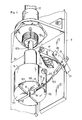
- the gripping device shown by way of example in the figures comprises a gripping assembly secured to a vertical plate 6 carried by a chassis equipped with air blowing means (not shown); this chassis, these blowing means and the fixing of the plate to the chassis are similar to those described in the patents FR 84.04804 or US 4,635,918 already mentioned and will not be described again.
- the plate 6 supports the body of a double-acting pneumatic cylinder 12 whose movable rod 12b is directed downwards in a substantially vertical position.
- this jack 12 is associated with a proximity sensor (not visible).
- a gripping head 14 is screwed onto the end of the rod 12b of the jack, so as to be able to move in a vertical translational movement (as in the main application, guide means prevent the head from rotating on itself and guide it in translation).
- This head is formed by a cylinder portion, the lower base of which is intended to act as a bearing surface for the tissue to be grasped.
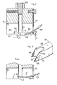
- This circular base comprises a step from a few tenths of a millimeter to a few millimeters and consists of two flat zones, one 100 set back from the other 101. In the example, these two zones are separated by a rectilinear shoulder 102, the depth of which may in particular be between 0.2 and 1 mm depending on the thickness of the layers to be gripped. A depth of 0.4 mm is ideal for very thin layers a few tenths of a millimeter thick.
- the head 14 is split with a thin blind groove 15 of thickness slightly greater than that of the needle described below. This groove extends in a vertical plane substantially perpendicular to the zones 100 and 101 and opens out along a diameter perpendicular to the shoulder 102.
- the head 14 has an openwork part 16, in the example of circular section, which opens onto the recessed surface 100, in the center of the head.
- This perforated part 16 extends on either side of the plane containing the groove 15 which cuts it diametrically.
- the shoulder 102 passes near said perforated part, the projecting area 101 extending on one side thereof, the recessed area extending towards the other side; in the example, the shoulder 102 is approximately tangent to the perforated part 16.
- the bearing surface is provided in its recessed area 100 with two bearing pins 110 and 111, located on either side of the groove 15, on the edge of said recessed area.
- these pins are carried by a guide plate 25 fixed at the edge of the head.
- These support lugs, located on each side of the base of the plate 25, are dimensioned to project up to level N of the projecting zone 101.
- the plate 6 carries means for kinematically guiding a needle 103.
- These means consist of members similar to those described in the main application: support 17 secured to the plate 6 in a position transversely offset with respect to the head , hinge pin 20 carried by the support 17 around which a link 21 can pivot, elastic means 22 urging the link (and therefore the needle) in the direction of its spacing relative to the head, pressure screw 24 for fixing of the needle 103 by its heel.
- These means are arranged so that the needle is located in the plane of the groove 15 and can move in this plane relative to the head, by rotation of the link 21 around its axis 20.
- the needle 103 is a curved needle whose concavity is oriented towards the bearing surface of the head. It passes through a light 112 formed in the guide plate 25 already mentioned, which is fixed at the edge of the head. This light has a dimension much greater than that of the needle so as to leave the latter with a faculty of movement towards the bearing surface, the elastic means 22 tending to press the needle against the lower edge of said light. (which defines the extreme stop position).
- the needle is shaped to have at its end two separate tips 104 and 105 and a stopper 106; the latter is formed by the part located between the bases of said points. These points can protrude by approximately 3/10 to 6/10 mm from the retainer.
- Each point has a beveled front edge such as 107, oriented so that the angular part 108 of said edge (part located opposite the bearing surface, called to come first into contact with the fabric) forms an acute angle ⁇ , in particular of the order of 60 to 80 °, and is projecting at the front relative to the other angular part 109 (located opposite the bearing surface).
- the kinematic guide means (light of the wafer 25, link 21, support 17) are arranged to impose on the needle an initial position as shown diagrammatically in FIG. 2.
- the end of the latter protrudes by relative to the recessed area 100, but also relative to the level N of the area 101; in this initial position, the needle end is located in the vicinity of the perforated part 16.
- the overflow -S- of the needle relative to the level N can be of the order of a few tenths of a millimeter.
- the tangent at its end forms a small angle ⁇ with respect to a plane parallel to the bearing surface.
- This angle can be of the order of a few degrees (up to 20 to 30 °).
- the needle comes into contact almost tangentially with the upper layer of fabric when the bearing surface is arranged against a stack of layers.
- the needle is guided so that, during its movement, it crosses the perforated part 16 to come at the end of movement in a final position as shown in FIG. 4.
- the trajectory has been shown diagrammatically in this figure. T of the needle end assuming that the needle was not repelled by a layer of fabric.
- the two end points 104 and 105 engage in the groove 15 (half of the groove opposite the half by which the needle arrives).
- the stopper 106 which is located at the base of the points is located approximately at the intersection between the groove and the perforated part.
- the needle is thus able to pinch the fold of the tissue, which was formed in the first part of the movement.
- FIGS 5a, 5b and 5c illustrate the operation of the device.
- FIG. 6 shows a detail of the head, seen from the side of the plate 25.
- the needle 103 rests against the part C2 of the upper layer and is slightly repelled by the latter: this produces an elastic support, of low penetration angle.
- the relative approximation between the stack and the head (FIG. 5b) generates a retraction of the head upwards and a movement of the needle towards the head and towards the perforated part 16 thereof: the angular parts 108 of the end of needle hook the top layer of fabric.
- the stopper 106 located between the points limits the penetration thereof.
- the elasticity of the support contributes to guaranteeing a surface attachment.
- the needle arrives in a position as shown diagrammatically in FIG. 5c. It pinches the fold of the fabric at the intersection of the groove and the openwork part. Only the short points protruding from the retainer penetrate the fabric.
- the proximity sensor controls the pneumatic supply of the jack 12 which locks the head in the high position.
- the firmly held fabric layer is thus locked and cannot come off.
- the stack is then separated from the head and the operations of transferring and then depositing the captured layer can be carried out.
Landscapes
- Engineering & Computer Science (AREA)
- Mechanical Engineering (AREA)
- Sheets, Magazines, And Separation Thereof (AREA)
Applications Claiming Priority (2)
| Application Number | Priority Date | Filing Date | Title |
|---|---|---|---|
| FR8602951 | 1986-02-24 | ||
| FR8602951A FR2594814B2 (fr) | 1986-02-24 | 1986-02-24 | Dispositif perfectionne de prehension de couches souples, en particulier textiles |
Publications (2)
| Publication Number | Publication Date |
|---|---|
| EP0240040A2 true EP0240040A2 (de) | 1987-10-07 |
| EP0240040A3 EP0240040A3 (de) | 1989-03-15 |
Family
ID=9332699
Family Applications (1)
| Application Number | Title | Priority Date | Filing Date |
|---|---|---|---|
| EP87200242A Withdrawn EP0240040A3 (de) | 1986-02-24 | 1987-02-16 | Vorrichtung zum Vereinzeln flexibler Flächengebilde, insbesondere Textilwaren |
Country Status (6)
| Country | Link |
|---|---|
| US (1) | US4822020A (de) |
| EP (1) | EP0240040A3 (de) |
| JP (1) | JPS62211237A (de) |
| AU (1) | AU583976B2 (de) |
| BR (1) | BR8700866A (de) |
| FR (1) | FR2594814B2 (de) |
Cited By (1)
| Publication number | Priority date | Publication date | Assignee | Title |
|---|---|---|---|---|
| EP0518009A1 (de) * | 1991-06-13 | 1992-12-16 | Kolbus GmbH & Co. KG | Verfahren und Vorrichtung zum Vereinzeln von Textilflächen von einem Stapel |
Families Citing this family (2)
| Publication number | Priority date | Publication date | Assignee | Title |
|---|---|---|---|---|
| FR2633267B1 (fr) * | 1988-06-27 | 1990-10-19 | Rouleau Patrick | Procede et dispositif pour superposer au moins deux couches souples, notamment un panneau de dos et un panneau de devant d'un article tel qu'un slip dans l'industrie textile et de la bonneterie |
| CN111824808A (zh) * | 2020-08-14 | 2020-10-27 | 宁波聚华光学科技有限公司 | 抓取布料用的针爪机构 |
Family Cites Families (5)
| Publication number | Priority date | Publication date | Assignee | Title |
|---|---|---|---|---|
| US3583698A (en) * | 1969-11-06 | 1971-06-08 | Cluett Peabody & Co Inc | Ply separating module |
| FR2214292A5 (de) * | 1973-01-16 | 1974-08-09 | Ctre Etud Tech Ind Habillement | |
| BE883235A (nl) * | 1980-05-12 | 1980-11-12 | Byttebier Gaspar A H | Werkwijze en inrichting voor het opnemen van soepele vellen van een stapel |
| FR2561631B1 (fr) * | 1984-03-26 | 1986-08-29 | Rouleau Patrick | Procede et dispositif de prehension de couches souples en particulier textiles et machine pour la prehension et le transfert desdites couches |
| US4601463A (en) * | 1984-07-03 | 1986-07-22 | Matsuya Hoseikiki Hanbai Kabushiki Kaisha | Cloth gripping device |
-
1986
- 1986-02-24 BR BR8700866A patent/BR8700866A/pt unknown
- 1986-02-24 FR FR8602951A patent/FR2594814B2/fr not_active Expired
-
1987
- 1987-02-16 EP EP87200242A patent/EP0240040A3/de not_active Withdrawn
- 1987-02-20 AU AU69093/87A patent/AU583976B2/en not_active Ceased
- 1987-02-21 JP JP62038731A patent/JPS62211237A/ja active Pending
- 1987-02-24 US US07/017,479 patent/US4822020A/en not_active Expired - Fee Related
Cited By (1)
| Publication number | Priority date | Publication date | Assignee | Title |
|---|---|---|---|---|
| EP0518009A1 (de) * | 1991-06-13 | 1992-12-16 | Kolbus GmbH & Co. KG | Verfahren und Vorrichtung zum Vereinzeln von Textilflächen von einem Stapel |
Also Published As
| Publication number | Publication date |
|---|---|
| FR2594814B2 (fr) | 1988-05-13 |
| US4822020A (en) | 1989-04-18 |
| JPS62211237A (ja) | 1987-09-17 |
| FR2594814A2 (fr) | 1987-08-28 |
| AU6909387A (en) | 1987-08-27 |
| BR8700866A (pt) | 1987-12-22 |
| EP0240040A3 (de) | 1989-03-15 |
| AU583976B2 (en) | 1989-05-11 |
Similar Documents
| Publication | Publication Date | Title |
|---|---|---|
| EP0509932B1 (de) | Verriegelungsvorrichtung für einen Behälter mit Deckel und Behälter mit einer solchen Vorrichtung | |
| WO1987005484A1 (fr) | Instrument microchirurgical a usage de pince ou de ciseaux | |
| EP0277896B1 (de) | Schwenkbare Stützvorrichtung für die Räder eines Fahrzeuges, paarweise verwendbar, insbesondere auf Autotransportfahrzeugen | |
| EP0077277A1 (de) | Verfahren und Vorrichtung zur Anbringung von Blutgefässklammern und Blutgefässklammern dafür | |
| FR2751863A1 (fr) | Support de clips hemostatiques | |
| WO2005046368A1 (fr) | Dispositif coupe-cigares | |
| FR2785952A1 (fr) | Attache rapide pour fixer un outil a l'extremite du bras d'un chargeur ou analogue | |
| EP0161010B1 (de) | Verfahren und Vorrichtung zum Vereinzeln flexibler Flächengebilde, insbesondere Textilwaren und Maschine zum Vereinzeln und zur Führung dieser Flächengebilde | |
| EP0240040A2 (de) | Vorrichtung zum Vereinzeln flexibler Flächengebilde, insbesondere Textilwaren | |
| FR3061645A1 (fr) | Poignee amovible munie d'un systeme d'ouverture avec un bouton pivotant | |
| FR2779943A1 (fr) | Chambre artificielle pour prelevement d'un greffon de cornee | |
| FR2591207A1 (fr) | Procede et dispositif de separation de pieces textiles. | |
| EP1296596B1 (de) | Medizinische zange mit zwei schwenkbaren backen | |
| EP0645329B1 (de) | Vorrichtung zum Trennen von Doppelentnahmen und Entstapelvorrichtung für flache Gegenstände mit einer solchen Trennvorrichtung | |
| FR2656226A1 (fr) | Fixation de securite pour ski. | |
| FR2588605A1 (fr) | Systeme manoeuvrable d'arret d'un battant de volet et ensemble de crochetage dudit battant. | |
| EP0115972B1 (de) | Versenkbarer Sitz mit kippbarer Rückenlehne | |
| FR2605612A1 (fr) | Dispositif d'acheminement de pieces avec ou sans retournement en vue de leur empilage | |
| FR2473982A1 (fr) | Agencement d'aile et de volet pour avions | |
| EP0159245B1 (de) | Scheibenwischanlage | |
| EP0292490B1 (de) | Verfahren und vorrichtung zum greifen eines biegsamen gegenstandes auf einem stapel | |
| CH642269A5 (fr) | Frein a ski. | |
| EP1191174B1 (de) | Sicherheitsvorrichtung für Ladenhaken | |
| FR2780615A1 (fr) | Scarificateur a patons | |
| FR2771061A1 (fr) | Essuie-glace de vehicule automobile comportant des moyens de verrouillage en position relevee |
Legal Events
| Date | Code | Title | Description |
|---|---|---|---|
| PUAI | Public reference made under article 153(3) epc to a published international application that has entered the european phase |
Free format text: ORIGINAL CODE: 0009012 |
|
| AK | Designated contracting states |
Kind code of ref document: A2 Designated state(s): AT BE CH DE ES GB GR IT LI LU NL SE |
|
| PUAL | Search report despatched |
Free format text: ORIGINAL CODE: 0009013 |
|
| AK | Designated contracting states |
Kind code of ref document: A3 Designated state(s): AT BE CH DE ES GB GR IT LI LU NL SE |
|
| 17P | Request for examination filed |
Effective date: 19890804 |
|
| STAA | Information on the status of an ep patent application or granted ep patent |
Free format text: STATUS: THE APPLICATION IS DEEMED TO BE WITHDRAWN |
|
| 18D | Application deemed to be withdrawn |
Effective date: 19900828 |