EP0239554B1 - Système d'alimentation pour brûleurs à gaz - Google Patents
Système d'alimentation pour brûleurs à gaz Download PDFInfo
- Publication number
- EP0239554B1 EP0239554B1 EP87850081A EP87850081A EP0239554B1 EP 0239554 B1 EP0239554 B1 EP 0239554B1 EP 87850081 A EP87850081 A EP 87850081A EP 87850081 A EP87850081 A EP 87850081A EP 0239554 B1 EP0239554 B1 EP 0239554B1
- Authority
- EP
- European Patent Office
- Prior art keywords
- gas
- profile
- conduit
- burner
- cocks
- Prior art date
- Legal status (The legal status is an assumption and is not a legal conclusion. Google has not performed a legal analysis and makes no representation as to the accuracy of the status listed.)
- Expired
Links
- 230000008878 coupling Effects 0.000 claims description 14
- 238000010168 coupling process Methods 0.000 claims description 14
- 238000005859 coupling reaction Methods 0.000 claims description 14
- 239000002184 metal Substances 0.000 claims description 13
- 230000000903 blocking effect Effects 0.000 claims 1
- 230000004048 modification Effects 0.000 description 2
- 238000012986 modification Methods 0.000 description 2
- 238000005452 bending Methods 0.000 description 1
- 238000010276 construction Methods 0.000 description 1
- 238000010438 heat treatment Methods 0.000 description 1
- 238000004519 manufacturing process Methods 0.000 description 1
- 229920003023 plastic Polymers 0.000 description 1
- 239000004033 plastic Substances 0.000 description 1
Images


Classifications
-
- F—MECHANICAL ENGINEERING; LIGHTING; HEATING; WEAPONS; BLASTING
- F24—HEATING; RANGES; VENTILATING
- F24C—DOMESTIC STOVES OR RANGES ; DETAILS OF DOMESTIC STOVES OR RANGES, OF GENERAL APPLICATION
- F24C3/00—Stoves or ranges for gaseous fuels
- F24C3/12—Arrangement or mounting of control or safety devices
- F24C3/126—Arrangement or mounting of control or safety devices on ranges
Definitions
- the present invention relates to a supply system for gas burners, preferably included in a range, according to the preamble of Claim 1.
- a burner In a known gas range in every heating position a burner is fixedly disposed. Gas is supplied to the burner via a separate gas conduit connected to a main conduit via a gas cock situated at the front of the range.
- the main conduit has the shape of a tube which extends along the front edge of the range and to which all gas cocks are connected.
- the gas conduits leading to the burners most often have the shape of thin tubes which have been bent to a shape predetermined for each connection.
- conduits 36 and 37 are included which, however, are to be considered more as main conduits than as gas conduits leading to the burners. From Fig. 2 it can be noted that the burners are fed in parallel rather than supplied via separate gas conduits and cocks from a main gas conduit. In Fig. 3 it is shown that via one of the conduits 36 or 37 two of the burners are simultaneously supplied while via the other conduit, 36 or 37, all four burners are supplied simultaneously.
- the object of the invention is to remedy the drawbacks indicated and to provide a gas supply system which is flexible and which permits the position of burners and of the cocks to be varied without changes in the basic construction of the cooker tops.
- the object will be achieved in a gas supply system having the characterizing features indicated in Claim 1. Preferred embodiments appear fom the sub-claims.
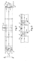
- Fig. 1 schematically shows a first embodiment.
- Fig. 2 is a view along the line II - II in Fig. 1 which schematically illustrates part of the gas supply system is an enlarged scale.
- Fig. 3 is a view along the line III - III in Fig. 2 schematically illustrating a section of the system having two cocks.
- Fig. 4 shows a section through a metal profile used in the embodiment according to Figs. 1 - 3 and incorporating gas conduits.
- Fig. 5 shows a coupling for connecting of a burner, whereas Fig. 6 illustrates a coupling for connecting of a cock.
- Fig. 7 illustrates a second embodiment of the gas supply system.
- Fig. 8 is a schematic view along the line VIII - VIII in Fig. 7 and Fig. 9, finally, is a view along the line IX - IX in Fig. 8.
- a cooker top 10 is schematically shown as seen from above.
- a metal profile 11 is disposed on the upper side of the cooker top to which it is secured by means of mounting angles 12 (Fig. 2) and screws, not shown.
- the mounting angles can be disposed at the ends of the profile and eventually in additional positions.
- the profile extends along the front edge 13 of the cooker top where it is connected to a number of cocks 14.
- the cocks and the profile are together secured to an elongate mounting angle 15 (Fig. 6) which is fixed to the cooker top in a way not shown in detail.
- the metal profile has the section shown in Fig. 4.
- the profile has three conduits 16, 17, 18 of which conduit 16 is a main conduit and the conduits 17, 18 are gas conduits leading to burners schematically indicated in Fig. 1.
- the burners which are designated 19, 20, 21, 22, are connected to the profile via a coupling 23 shown in Fig. 5.
- the coupling is pushed onto the profile 11 and fixed thereto by a clamp joint comprising a bolt 47 and a nut 48 which cooperate with two flanges 49, 50.
- the burners are supported by the metal profile via the respective coupling 23.
- the conduits 16, 17, 18 extend through the whole metal profile 11, one end of which being connected to a gas mains via a schematic joint 24 in the form of the mounting angle 12 shown in Fig. 2 being provided with a connecting pipe 25 for a connecting hose or the like, now shown.
- a cover 26 which can be of the same shape as the mounting angle 12, however without the connecting pipe 25.
- the joint 24 and the cover 26 may be secured by screws 28 being screwed into the holes of the conduits 17, 18.
- Fig. 2 there is shown the connection of the cocks 14 to the metal profile 11 by a coupling 29.
- the coupling comprises a cock housing 29 which by screws 31 is secured to the metal profile from the side and with an intermediate gasket 30.
- gas is supplied in parallel to the cocks 24 from the main conduit 16.
- the upper gas conduit 17 is served by a first cock 14a and also by a second cock 14b.
- the burners served by the cocks 14a, 14b are situated at opposite sides of the cocks so that with reference to Fig. 1 cock 14a, for example, is serving the burner 21, whereas cock 14b is serving the burner 20.
- two additional cocks can serve the burners 19 and 22.
- the gas conduit is split up into two parts 17a, 17b where the conduit 17a leads to the burner 21 and the conduit 17b leads to the burner 20.
- the area between the conduits 17a and 17b is plugged up. For example, this can be done by making a hole 32 in the profile of a diameter slightly larger than that of the conduit 17 and then pressing a metal plug 33 into the hole.
- a gas main conduit has been integrated into the metal profile. This is not always a necessity but one can think of providing a joint 34, see Fig. 7, corresponding to the joint 24 in Fig. 1.
- the profile 35 has a section according to Fig. 8 having only two gas conduits 36, 37.
- the profile is connected to burners 38, 39, 40, 41 in a similar way as in the embodiment of Fig. 1.
- the conduits 36, 37 are directly connected to the gas mains via the joint 34.
- four cocks 42, 43, 44, 45 are shown and the joint 34 is disposed between the central cocks 43 and 44.
- This embodiment relates to a built-in hob and the control shafts of the cocks are directed vertically, see Figs. 8 and 9 showing the gas flow through one of the cocks 42 - 45.
- the cocks 43 and 44 can feed the burners 39 and 40, respectively, via the upper gas conduit 36 whereas the cocks 42 and 45 can feed the burners 38 and 41, respectively, via the lower gas conduit 37.
- Fig. 9 it appears how the gas is led from a conduit part 36a into a cock housing 52 via a cock plug 53 and into a gas conduit 36b leading to the burner 39.
- the space between the conduit parts 36a and 36b must be plugged up and this can be done by a fixing screw, not shown, securing the cock housing 52 to the metal profile 35. Thus, this screw can be screwed into the conduit 37 to block it up.
- the same hob can be used for a number of different variants being equipped with only gas burners or having a mixed outfit comprising burners and electric hot plates.
- the profile can be made of metal or plastics and in the first-mentioned case the profile can be given its final form by bending in order to connect the different burners with their respective cocks.
- the connection to the mains can be made at one end of the profile or in the area where the cocks are situated.
- the different couplings for connecting of the burners and for connecting of the cocks are constructed so as to permit connection to all gas conduits in the profile, whereas the profile in the respective position of a burner or a cock only has those openings which are required for the selective connection of the burner or the cock, respectively, to the desired gas conduit.
- the profile has such rigidity so as to alone easily be able to support all burners and then be secured to the cooker top by simple mounting angles.
Landscapes
- Engineering & Computer Science (AREA)
- Chemical & Material Sciences (AREA)
- Combustion & Propulsion (AREA)
- Mechanical Engineering (AREA)
- General Engineering & Computer Science (AREA)
- Feeding And Controlling Fuel (AREA)
- Gas Burners (AREA)
Claims (7)
- Système d'alimentation pour brûleurs à gaz (19, 20, 21, 22) insérés dans une table de cuisson, du gaz étant fourni à chaque brûleur par l'intermédiaire d'une conduite de gaz séparée (17, 18) et d'un robinet de gaz (14), lesdites conduites de gaz étant approvisionnées à partir d'une conduite principale (16) qui fait partie de la table de cuisson et est reliée a un réseau de gaz, chaque robinet, par l'intermédiaire d'un accouplement (29), étant de plus, relié à la conduite principale (16) et à sa conduite de gaz respective (17, 18) qui, par l'intermédiaire d'un accouplement correspondant (23), est reliée au brûleur (19, 20, 21, 22), caractérisé en ce que les conduites de gaz (17, 18) sont définies par un profilé allongé (11) qui est agencé afin de passer successivement à tous les emplacements de brûleurs aussi bien que dans la région où les robinets sont situés.
- Système selon la revendication 1, caractérisé en ce que la conduite principale (16) est aussi contenue dans le profilé (11).
- Système selon la revendication 2, caractérisé en ce que les conduites (16, 17, 18) s'étendent à travers tout le profilé (11), au moins une extrémité du profilé étant obturée par des moyens (24, 26) bloquant la conduite respective.
- Système selon la revendication 2, caractérisé en ce que la conduite principale (16) est reliée au réseau de gaz par l'intermédiaire d'un accouplement (24) disposé à une extrémité du profilé.
- Système selon la revendication 3 ou 4, caractérisé en ce que la région comprenant les robinets (14) est située de telle façon que le profilé (11) dès deux côtés de cette région, s'étend jusqu'au brûleur respectif (19, 20, 21, 22), la même conduite de gaz (17) traversante étant reliée à deux robinets (14a, 14b) de telle sorte que la partie (17a) de la conduite de gaz s'étendant dans une direction à partir de la région des robinets forme un premier circuit séparé pour servir un premier brûleur (21), tandis que la seconde partie (17b) de la conduite de gaz forme un second circuit séparé pour servir un second brûleur (20).
- Système selon l'une quelconque des revendications précédentes, caractérisé en ce que les accouplements (23) pour la liaison des brûleurs et les accouplements (29) pour la liaison des robinets sont agencés afin de permettre la liaison de toutes les conduites de gaz du profilé, tandis que le profilé (11) à l'emplacement de brûleur respectif et à l'emplacement respectif d'un robinet, est pourvu seulement des ouvertures requises pour la liaison sélective du brûleur et du robinet à la conduite de gaz.
- Système d'alimentation selon l'une quelconque des précédentes revendications, caractérisé en ce que le profilé allongé (11) est fait de métal.
Applications Claiming Priority (2)
| Application Number | Priority Date | Filing Date | Title |
|---|---|---|---|
| SE8601433 | 1986-03-27 | ||
| SE8601433A SE460222B (sv) | 1986-03-27 | 1986-03-27 | Anordning foer tillfoersel av braensle till foeretraedesvis i en spis ingaaende gasbraennare |
Publications (3)
| Publication Number | Publication Date |
|---|---|
| EP0239554A2 EP0239554A2 (fr) | 1987-09-30 |
| EP0239554A3 EP0239554A3 (en) | 1989-02-08 |
| EP0239554B1 true EP0239554B1 (fr) | 1991-08-07 |
Family
ID=20363988
Family Applications (1)
| Application Number | Title | Priority Date | Filing Date |
|---|---|---|---|
| EP87850081A Expired EP0239554B1 (fr) | 1986-03-27 | 1987-03-13 | Système d'alimentation pour brûleurs à gaz |
Country Status (5)
| Country | Link |
|---|---|
| US (1) | US4754744A (fr) |
| EP (1) | EP0239554B1 (fr) |
| CA (1) | CA1276870C (fr) |
| DE (1) | DE3771900D1 (fr) |
| SE (1) | SE460222B (fr) |
Families Citing this family (5)
| Publication number | Priority date | Publication date | Assignee | Title |
|---|---|---|---|---|
| US5836296A (en) * | 1996-09-24 | 1998-11-17 | Lincoln Brass Works, Inc. | Manifold with integral burner control and oven control |
| US5829425A (en) * | 1996-02-16 | 1998-11-03 | Lincoln Brass Works, Inc. | Integral burner control and manifold |
| US5979430A (en) * | 1998-02-06 | 1999-11-09 | Universal Tubular Systems, Inc. | Supply device for gas appliance manifold |
| ITMI20050837A1 (it) * | 2005-05-11 | 2006-11-12 | Enzo Inzaghi | Piano di cottura con distribuzione delle fiamme ottimizzata |
| US8033279B2 (en) * | 2008-11-25 | 2011-10-11 | General Electric Company | Burner control system for a cooking appliance |
Family Cites Families (6)
| Publication number | Priority date | Publication date | Assignee | Title |
|---|---|---|---|---|
| DE1251490B (fr) * | 1967-10-05 | |||
| US1574940A (en) * | 1924-04-11 | 1926-03-02 | Baltimore Trust Company | Gas range |
| US1820277A (en) * | 1928-07-02 | 1931-08-25 | Eagle Foundry Company | Gas stove |
| US1962251A (en) * | 1932-06-27 | 1934-06-12 | Magin Rudolph | Gas burner control unit |
| US2993532A (en) * | 1959-02-09 | 1961-07-25 | Robertshaw Fulton Controls Co | Gas range structure |
| FR2177598B3 (fr) * | 1972-03-31 | 1975-06-20 | Martin Usines Fonderie Arthur |
-
1986
- 1986-03-27 SE SE8601433A patent/SE460222B/sv not_active IP Right Cessation
-
1987
- 1987-03-12 CA CA000531853A patent/CA1276870C/fr not_active Expired - Fee Related
- 1987-03-12 US US07/024,990 patent/US4754744A/en not_active Expired - Fee Related
- 1987-03-13 EP EP87850081A patent/EP0239554B1/fr not_active Expired
- 1987-03-13 DE DE8787850081T patent/DE3771900D1/de not_active Expired - Fee Related
Also Published As
| Publication number | Publication date |
|---|---|
| DE3771900D1 (de) | 1991-09-12 |
| EP0239554A2 (fr) | 1987-09-30 |
| US4754744A (en) | 1988-07-05 |
| SE8601433L (sv) | 1987-09-28 |
| SE8601433D0 (sv) | 1986-03-27 |
| SE460222B (sv) | 1989-09-18 |
| CA1276870C (fr) | 1990-11-27 |
| EP0239554A3 (en) | 1989-02-08 |
Similar Documents
| Publication | Publication Date | Title |
|---|---|---|
| US4565523A (en) | Gas burner | |
| US6568713B1 (en) | Liquid distribution collector module and fixing system for said modules | |
| US7048538B2 (en) | Gas distribution assembly with rotary taps for a cooking appliance | |
| EP0239554A2 (fr) | Système d'alimentation pour brûleurs à gaz | |
| EP0624234A4 (fr) | Systeme de decharge de fluides. | |
| US6363971B1 (en) | Integrated gas valve assembly | |
| US4917077A (en) | Wall-mounted hot water boiler of the instant type | |
| US6082781A (en) | Pipe connecting device | |
| US4394562A (en) | Electric immersion heater mounting flange | |
| HUT74469A (en) | Panel radiator | |
| SK123396A3 (en) | Panel heating radiator | |
| EP0089713B1 (fr) | Armature lumineuse | |
| EP0241138A1 (fr) | Dispositif de commande pour appareil à gaz | |
| CN105804165B (zh) | 用于厨房混水龙头的连接单元以及所述单元的安置及连接方法 | |
| GB2316456A (en) | Gas supply arrangement for a gas cooking appliance | |
| EP0371715B1 (fr) | Assemblage modulaire d'un brûleur à gaz | |
| JPS5862441A (ja) | 暖房パネル床 | |
| US4224926A (en) | In-line manifold solar heat collectors | |
| GB2241564A (en) | Domestic water heating boilers | |
| GB2270356A (en) | Piping for gas hob | |
| JP3660206B2 (ja) | 給湯装置 | |
| ITMI940166U1 (it) | Collettore per impianti idraulici | |
| GB2266140A (en) | Cooker top | |
| EP0727617B1 (fr) | Fourneau de cuisine avec une table de cuisson autonome | |
| KR200163517Y1 (ko) | 가스계량기의 배관유니트 |
Legal Events
| Date | Code | Title | Description |
|---|---|---|---|
| PUAI | Public reference made under article 153(3) epc to a published international application that has entered the european phase |
Free format text: ORIGINAL CODE: 0009012 |
|
| AK | Designated contracting states |
Kind code of ref document: A2 Designated state(s): CH DE FR GB IT LI SE |
|
| PUAL | Search report despatched |
Free format text: ORIGINAL CODE: 0009013 |
|
| AK | Designated contracting states |
Kind code of ref document: A3 Designated state(s): CH DE FR GB IT LI SE |
|
| 17P | Request for examination filed |
Effective date: 19890228 |
|
| 17Q | First examination report despatched |
Effective date: 19900323 |
|
| GRAA | (expected) grant |
Free format text: ORIGINAL CODE: 0009210 |
|
| AK | Designated contracting states |
Kind code of ref document: B1 Designated state(s): CH DE FR GB IT LI SE |
|
| PG25 | Lapsed in a contracting state [announced via postgrant information from national office to epo] |
Ref country code: IT Free format text: LAPSE BECAUSE OF FAILURE TO SUBMIT A TRANSLATION OF THE DESCRIPTION OR TO PAY THE FEE WITHIN THE PRE;WARNING: LAPSES OF ITALIAN PATENTS WITH EFFECTIVE DATE BEFORE 2007 MAY HAVE OCCURRED AT ANY TIME BEFORE 2007. THE CORRECT EFFECTIVE DATE MAY BE DIFFERENT FROM THE ONE RECORDED.SCRIBED TIME-LIMIT Effective date: 19910807 Ref country code: SE Effective date: 19910807 |
|
| REF | Corresponds to: |
Ref document number: 3771900 Country of ref document: DE Date of ref document: 19910912 |
|
| EN | Fr: translation not filed | ||
| PG25 | Lapsed in a contracting state [announced via postgrant information from national office to epo] |
Ref country code: FR Effective date: 19911227 |
|
| PG25 | Lapsed in a contracting state [announced via postgrant information from national office to epo] |
Ref country code: GB Effective date: 19920313 |
|
| PG25 | Lapsed in a contracting state [announced via postgrant information from national office to epo] |
Ref country code: LI Effective date: 19920331 Ref country code: CH Effective date: 19920331 |
|
| PLBE | No opposition filed within time limit |
Free format text: ORIGINAL CODE: 0009261 |
|
| STAA | Information on the status of an ep patent application or granted ep patent |
Free format text: STATUS: NO OPPOSITION FILED WITHIN TIME LIMIT |
|
| 26N | No opposition filed | ||
| GBPC | Gb: european patent ceased through non-payment of renewal fee | ||
| REG | Reference to a national code |
Ref country code: CH Ref legal event code: PL |
|
| PG25 | Lapsed in a contracting state [announced via postgrant information from national office to epo] |
Ref country code: DE Effective date: 19921201 |
|
| REG | Reference to a national code |
Ref country code: FR Ref legal event code: ST |