EP0238491B1 - Separateur cyclone - Google Patents
Separateur cyclone Download PDFInfo
- Publication number
- EP0238491B1 EP0238491B1 EP85905746A EP85905746A EP0238491B1 EP 0238491 B1 EP0238491 B1 EP 0238491B1 EP 85905746 A EP85905746 A EP 85905746A EP 85905746 A EP85905746 A EP 85905746A EP 0238491 B1 EP0238491 B1 EP 0238491B1
- Authority
- EP
- European Patent Office
- Prior art keywords
- oil
- cyclone separator
- outlet means
- component
- processing apparatus
- Prior art date
- Legal status (The legal status is an assumption and is not a legal conclusion. Google has not performed a legal analysis and makes no representation as to the accuracy of the status listed.)
- Expired - Lifetime
Links
- 239000000203 mixture Substances 0.000 claims abstract description 34
- 238000012545 processing Methods 0.000 claims abstract description 19
- 238000011282 treatment Methods 0.000 claims abstract description 10
- 239000000470 constituent Substances 0.000 claims abstract description 5
- 238000011084 recovery Methods 0.000 claims description 5
- 238000011221 initial treatment Methods 0.000 claims description 3
- 238000007599 discharging Methods 0.000 claims description 2
- 238000000926 separation method Methods 0.000 abstract description 14
- 239000003921 oil Substances 0.000 description 59
- XLYOFNOQVPJJNP-UHFFFAOYSA-N water Substances O XLYOFNOQVPJJNP-UHFFFAOYSA-N 0.000 description 16
- 239000010779 crude oil Substances 0.000 description 3
- 238000004945 emulsification Methods 0.000 description 3
- 238000012806 monitoring device Methods 0.000 description 2
- 230000002411 adverse Effects 0.000 description 1
- 238000010420 art technique Methods 0.000 description 1
- 238000004140 cleaning Methods 0.000 description 1
- 238000010276 construction Methods 0.000 description 1
- 238000007796 conventional method Methods 0.000 description 1
- 238000009291 froth flotation Methods 0.000 description 1
- 238000003780 insertion Methods 0.000 description 1
- 230000037431 insertion Effects 0.000 description 1
- 238000011835 investigation Methods 0.000 description 1
- 238000004519 manufacturing process Methods 0.000 description 1
- 238000000034 method Methods 0.000 description 1
- 239000000126 substance Substances 0.000 description 1
Images

Classifications
-
- B—PERFORMING OPERATIONS; TRANSPORTING
- B04—CENTRIFUGAL APPARATUS OR MACHINES FOR CARRYING-OUT PHYSICAL OR CHEMICAL PROCESSES
- B04C—APPARATUS USING FREE VORTEX FLOW, e.g. CYCLONES
- B04C5/00—Apparatus in which the axial direction of the vortex is reversed
- B04C5/24—Multiple arrangement thereof
-
- B—PERFORMING OPERATIONS; TRANSPORTING
- B01—PHYSICAL OR CHEMICAL PROCESSES OR APPARATUS IN GENERAL
- B01D—SEPARATION
- B01D17/00—Separation of liquids, not provided for elsewhere, e.g. by thermal diffusion
- B01D17/02—Separation of non-miscible liquids
-
- B—PERFORMING OPERATIONS; TRANSPORTING
- B01—PHYSICAL OR CHEMICAL PROCESSES OR APPARATUS IN GENERAL
- B01D—SEPARATION
- B01D17/00—Separation of liquids, not provided for elsewhere, e.g. by thermal diffusion
- B01D17/02—Separation of non-miscible liquids
- B01D17/0217—Separation of non-miscible liquids by centrifugal force
-
- B—PERFORMING OPERATIONS; TRANSPORTING
- B01—PHYSICAL OR CHEMICAL PROCESSES OR APPARATUS IN GENERAL
- B01D—SEPARATION
- B01D19/00—Degasification of liquids
- B01D19/0042—Degasification of liquids modifying the liquid flow
- B01D19/0052—Degasification of liquids modifying the liquid flow in rotating vessels, vessels containing movable parts or in which centrifugal movement is caused
- B01D19/0057—Degasification of liquids modifying the liquid flow in rotating vessels, vessels containing movable parts or in which centrifugal movement is caused the centrifugal movement being caused by a vortex, e.g. using a cyclone, or by a tangential inlet
-
- B—PERFORMING OPERATIONS; TRANSPORTING
- B01—PHYSICAL OR CHEMICAL PROCESSES OR APPARATUS IN GENERAL
- B01D—SEPARATION
- B01D19/00—Degasification of liquids
- B01D19/0068—General arrangements, e.g. flowsheets
-
- E—FIXED CONSTRUCTIONS
- E21—EARTH OR ROCK DRILLING; MINING
- E21B—EARTH OR ROCK DRILLING; OBTAINING OIL, GAS, WATER, SOLUBLE OR MELTABLE MATERIALS OR A SLURRY OF MINERALS FROM WELLS
- E21B43/00—Methods or apparatus for obtaining oil, gas, water, soluble or meltable materials or a slurry of minerals from wells
- E21B43/34—Arrangements for separating materials produced by the well
- E21B43/38—Arrangements for separating materials produced by the well in the well
Definitions
- This invention relates generally to apparatus for the treatment or processing of mixtures containing oil such as crude oil and the like.
- separators of a unique type which can be used in the separation of oil/water mixtures where there is a relatively small amount of oil in the mixture (say less than 5%).
- separators of the kind described in United States patent specification 4,237,006 or International patent application PCT/ AU83/00028 (W083/03063) have been successfully used in cleaning the residue water which remains after the substantial part of the oil is removed from the crude oil mixture.
- the separation of the major part of the oil from the crude oil mixture has been generally carried out using separating tanks and the like.
- This invention provides improved apparatus and systems incorporating such apparatus which provide for more advantageous separation of the oil from a mixture than prior art techniques.
- oil processing apparatus for the treatment of a mixture containing oil and other constituents
- the apparatus comprising a primary treatment section which includes one or more primary cyclone separators the or each primary cyclone separator having inlet means and first and second outlet means, said primary cyclone separator(s) being of the type capable of handling a mixture containing a relatively high percentage of oil and of separating the mixture into first and second components which are discharged from said first and second outlet means respectively with said first component being relatively highly concentrated in oil and said second component being of relatively low concentration
- the apparatus further including a secondary treatment section which includes one or more secondary cyclone separators the or each secondary cyclone separator including inlet means operatively connected to said second outlet means of said primary cyclone separators, said secondary cyclone separator(s) further including first and second outlet means and being of the type capable of handling mixtures containing a relatively low percentage of oil and of separating the mixture received from said second outlet means of said primary cyclone separator(s) into
- the first outlet means of the primary cyclone separator(s) is operatively connected to means for removing gas from the first component.
- first outlet means of the secondary cyclone separator(s) is operatively connected to means for removing gas from the first component.
- first outlet means of the primary and secondary cyclone separators are operatively connected to a common discharge line. Further, the separated gas may be compressed and returned to the oil discharge line.
- an oil recovery system for recovering oil from an underground reservoir from which a mixture containing oil and other constituents can be discharged, comprises a line disposed in a cavity between the reservoir and the ground surface and oil processing apparatus for at least partially separating the oil from the other components in the mixture said apparatus being operatively connected with said line and at least part of said apparatus being disposed below the ground surface within said cavity.
- the oil processing apparatus is of the type described hereinbefore.
- At least the secondary treatment section of the oil processing apparatus is disposed below the surface. Further, there may be provided means for discharging the second component from said secondary cyclone separator(s) to a subterranean cavity.
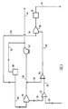
- oil in a line 20 from the well head is passed to a cyclone separator of the type capable of handling high concentration of oil with the water dispersed in the oil, designated by reference numeral 22 this separator defining the primary treatment section.
- a line 24 therefrom at the underflow outlet end carries oily water and gas to the inlet of a second hydrocyclone 26, ofthe type capable of handling relatively low concentrations of oil with the oil dispersed in the water this separator defining the secondary treatment section.
- the underflow outlet of this separator 26 is passed on a line 28 to a cyclone water degasser 30 thence through an oil content monitoring device 32to a clean water outlet34.
- Oil and gas taken from the overflow outlet of the separator 22 passes on a line 36 to the inlet of a cyclone oil degasser 38.
- Oil from the underflow outlet of degasser 38 is taken on a line 40 through a pump 42 to an oil outlet line 44.
- Oil from the separator 26 may be taken on a line 46 from the overflow outlet of separator 26 and added to line 40.
- the overflow outlet of degasser 38 is connected to a line 48 which carries gas from the degasser 48 through a gas compressor 50 to pass the gas via a line 52 to the line 44 so that gas is also carried on the line 44.
- the gas from the overflow outlet from the degasser 30 is taken on a line 56 and added to line 48.
- the cyclone separator 26 may be of the type described in United States patent 4,237,006 or International application No. PCT/AU83/00028 (W083/03063).
- the cyclone oil degasser 38 may be omitted as may be the cyclone water degasser 30.
- the oil pump 42 and gas compressor 50 may likewise be unnecessary in some instances.
- either the pump 66 or the separator60 may be omitted.
- a vessel may be provided in line 24 between primary cyclone 22 and secondary cyclone 26 for removal of a component such as gas.
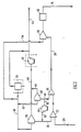
- FIG. 3 there is shown a system for recovering oil from a subterranean well which uses apparatus of the type described above which is disposed within a downhole cavity 80 which is the cavity which connects the oil reservoir 82 to the well head above ground (not shown),
- Oil is admitted into the cavity 80 at its lower end 80a and thence passed to a line 20 which leads to the inlet of a cyclone separator of one type capable of handling high concentrations of oil with the water dispersed in the oil, designated by reference numeral 22.
- a line 24 therefrom at the underflow outlet end carries oilywater and gas to the inlet of a second cyclone separator 26, capable of handling mixtures containing low concentrations of oil with the oil dispersed in the water.
- the underflow outlet of this separator 26 is passed on a line 28 to a cyclone water degasser 30 thence through an oil content monitoring device 32 to a clean water outlet 34.
- Oil and gas taken from the overflow outlet of the separator 22 passes on a line 36 to the inlet of a cyclone oil degassser 38.
- Oil from the underflow outlet of degasser 38 is taken on a line 40 through a pump 42 to an oil outlet line 44.
- Oil from the separator 26 may be taken on a line 46 from the overflow outlet of separator 26 and added to line 40.
- the overflow outlet of degasser 38 is connected to a line 48 which carries gas from the degasser 48 through a gas compressor 50 to pass the gas via a line 52 to the line 44 so that gas is also carried on the line 44.
- the gas from the overflow outlet from the degasser 30 is taken on a line 56 and added to line 48.
- oil can be taken on the line 44 to the surface of the well for further processing.
- the water in line 34 may likewise be taken to the surface or, alternatively, could simply be returned to the oil reservoir or to another reservoir which has been exhausted or partly exhausted at a higher level than the reservoir 82. This may be effected by outflow from a suitable exhaust arrangement in the pipeline.
- the separating technique of this invention has the advantage that the cyclone separators which are used do not induce substantial shear in the mixtures being separated so that there is no great emulsification of the mixtures, which emulsification hampers separation.
- conventional techniques employing separating vessels ususally require the insertion of pressure- reducing chokes into the mixture flow lines from the sources. These induce substantial shear in the mixture and cause emulsification which adversely affects separation.
- the admitted mixture for separation will generally be at relatively high temperature and pressures, thereby greatly assisting separation.
Landscapes
- Chemical Kinetics & Catalysis (AREA)
- Chemical & Material Sciences (AREA)
- Physics & Mathematics (AREA)
- Geology (AREA)
- Life Sciences & Earth Sciences (AREA)
- Engineering & Computer Science (AREA)
- Thermal Sciences (AREA)
- Mining & Mineral Resources (AREA)
- Environmental & Geological Engineering (AREA)
- Fluid Mechanics (AREA)
- General Life Sciences & Earth Sciences (AREA)
- Geochemistry & Mineralogy (AREA)
- Cyclones (AREA)
- Production Of Liquid Hydrocarbon Mixture For Refining Petroleum (AREA)
- Lubricants (AREA)
- Fats And Perfumes (AREA)
Abstract
Claims (10)
Priority Applications (1)
| Application Number | Priority Date | Filing Date | Title |
|---|---|---|---|
| AT85905746T ATE60721T1 (de) | 1984-11-28 | 1985-11-28 | Zyklonabscheidevorrichtung. |
Applications Claiming Priority (4)
| Application Number | Priority Date | Filing Date | Title |
|---|---|---|---|
| AU8335/84 | 1984-11-28 | ||
| AUPG833584 | 1984-11-28 | ||
| AUPG904185 | 1985-01-25 | ||
| AU9041/85 | 1985-01-25 |
Publications (3)
| Publication Number | Publication Date |
|---|---|
| EP0238491A1 EP0238491A1 (fr) | 1987-09-30 |
| EP0238491A4 EP0238491A4 (fr) | 1988-06-13 |
| EP0238491B1 true EP0238491B1 (fr) | 1991-02-06 |
Family
ID=25642879
Family Applications (1)
| Application Number | Title | Priority Date | Filing Date |
|---|---|---|---|
| EP85905746A Expired - Lifetime EP0238491B1 (fr) | 1984-11-28 | 1985-11-28 | Separateur cyclone |
Country Status (11)
| Country | Link |
|---|---|
| US (1) | US4738779A (fr) |
| EP (1) | EP0238491B1 (fr) |
| CA (1) | CA1262531A (fr) |
| DE (1) | DE3581742D1 (fr) |
| EG (1) | EG17602A (fr) |
| GB (1) | GB2191120B (fr) |
| MX (1) | MX167588B (fr) |
| NL (1) | NL8520398A (fr) |
| NO (1) | NO172426B (fr) |
| OA (1) | OA08602A (fr) |
| WO (1) | WO1986003143A1 (fr) |
Cited By (1)
| Publication number | Priority date | Publication date | Assignee | Title |
|---|---|---|---|---|
| EP0834342A2 (fr) * | 1996-10-02 | 1998-04-08 | Camco International Inc. | Système de séparation des fluides de fond de puits |
Families Citing this family (69)
| Publication number | Priority date | Publication date | Assignee | Title |
|---|---|---|---|---|
| EP0422314B1 (fr) * | 1989-10-10 | 1994-04-13 | WIKDAHL, Nils Anders Lennart | Procédé et dispositif de production d'une dâte cellulosique de qualité améliorée |
| US5492622A (en) * | 1990-09-28 | 1996-02-20 | Broussard; Paul C. | Water clarification apparatus |
| US5158678A (en) * | 1990-09-28 | 1992-10-27 | Broussard Paul C Sr | Water clarification method and apparatus |
| EP0537174A4 (en) * | 1991-05-02 | 1993-09-22 | Conoco Specialty Products Inc. | Hydrocylones for oil spill cleanup |
| WO1992019348A1 (fr) * | 1991-05-02 | 1992-11-12 | Conoco Specialty Products Inc. | Systeme de separation petrole/eau |
| US5350525A (en) * | 1992-09-11 | 1994-09-27 | Conoco Specialty Products Inc. | System and process for hydrocyclone separation of particulate solids and at least one liquid phase from a multiphase liquid mixture |
| NO924896L (no) * | 1992-12-17 | 1994-06-20 | Read Process Engineering As | Nede-i-hullet prosess |
| US5296153A (en) * | 1993-02-03 | 1994-03-22 | Peachey Bruce R | Method and apparatus for reducing the amount of formation water in oil recovered from an oil well |
| NO933517L (no) * | 1993-10-01 | 1995-04-03 | Anil As | Fremgangsmåte ved utvinning av hydrokarboner i et underjordisk reservoar |
| US5456837A (en) * | 1994-04-13 | 1995-10-10 | Centre For Frontier Engineering Research Institute | Multiple cyclone apparatus for downhole cyclone oil/water separation |
| US5996690A (en) * | 1995-06-06 | 1999-12-07 | Baker Hughes Incorporated | Apparatus for controlling and monitoring a downhole oil/water separator |
| EP0830494B1 (fr) * | 1995-06-07 | 2000-03-29 | Centre For Engineering Research Inc. | Procede de cyclonage de fond de puits |
| US6080312A (en) * | 1996-03-11 | 2000-06-27 | Baker Hughes Limited | Downhole cyclonic separator assembly |
| US5772901A (en) * | 1996-04-30 | 1998-06-30 | Energy Biosystems Corporation | Oil/water/biocatalyst three phase separation process |
| GB9614675D0 (en) * | 1996-07-12 | 1996-09-04 | Baker Hughes Inc | Oil well production |
| US6000468A (en) * | 1996-08-01 | 1999-12-14 | Camco International Inc. | Method and apparatus for the downhole metering and control of fluids produced from wells |
| US6082452A (en) * | 1996-09-27 | 2000-07-04 | Baker Hughes, Ltd. | Oil separation and pumping systems |
| EP1445420A3 (fr) * | 1996-09-27 | 2004-09-08 | Baker Hughes Limited | Systèmes de séparation d'huile et de pompage |
| CA2271168A1 (fr) * | 1996-11-07 | 1998-05-14 | Baker Hughes Limited | Systeme de separation et de reinjection de fluides pour puits de petrole |
| US5961841A (en) * | 1996-12-19 | 1999-10-05 | Camco International Inc. | Downhole fluid separation system |
| WO1998036155A1 (fr) * | 1997-02-13 | 1998-08-20 | Baker Hughes Incorporated | Procede et dispositif de separation de fluides de fond de puits et de regulation de la production d'eau |
| NO321386B1 (no) * | 1997-03-19 | 2006-05-02 | Norsk Hydro As | Fremgangsmate og anordning for separering av et fluid omfattende flere fluidkomponenter, fortrinnsvis separering av et bronnfluid i forbindelse med et ror for produksjon av hydrokarboner/vann |
| US6089317A (en) * | 1997-06-24 | 2000-07-18 | Baker Hughes, Ltd. | Cyclonic separator assembly and method |
| NO308426B1 (no) * | 1998-07-13 | 2000-09-11 | Read Group As | FremgangsmÕte og innretning for produsering av et oljereservoar |
| US6173774B1 (en) * | 1998-07-23 | 2001-01-16 | Baker Hughes Incorporated | Inter-tandem pump intake |
| CA2247838C (fr) | 1998-09-25 | 2007-09-18 | Pancanadian Petroleum Limited | Systeme de fond de trou pour la separation petrole/eau et la separation des solides |
| US6336504B1 (en) | 2000-03-03 | 2002-01-08 | Pancanadian Petroleum Limited | Downhole separation and injection of produced water in naturally flowing or gas-lifted hydrocarbon wells |
| US6336503B1 (en) | 2000-03-03 | 2002-01-08 | Pancanadian Petroleum Limited | Downhole separation of produced water in hydrocarbon wells, and simultaneous downhole injection of separated water and surface water |
| NO313767B1 (no) | 2000-03-20 | 2002-11-25 | Kvaerner Oilfield Prod As | Fremgangsmåte for å oppnå samtidig tilförsel av drivfluid til flere undersjöiske brönner og undersjöisk petroleums-produksjons-arrangement for samtidig produksjon av hydrokarboner fra flereundersjöiske brönner og tilförsel av drivfluid til de s |
| US6457531B1 (en) | 2000-06-09 | 2002-10-01 | Wood Group Esp, Inc. | Water separation system with encapsulated electric submersible pumping device |
| US6457522B1 (en) | 2000-06-14 | 2002-10-01 | Wood Group Esp, Inc. | Clean water injection system |
| US6547003B1 (en) | 2000-06-14 | 2003-04-15 | Wood Group Esp, Inc. | Downhole rotary water separation system |
| US7017277B1 (en) | 2001-10-13 | 2006-03-28 | Adams Randall G | Vacuum treatment of an input stream without ruining delicate output fractions |
| US6754978B1 (en) | 2001-10-13 | 2004-06-29 | Micronics, L.L.C. | Vacuum treatment of waste stream |
| US7140122B1 (en) | 2001-10-13 | 2006-11-28 | Micronics, Llc | Vacuum treatment of waste stream with anti-incrustation measures |
| US7020980B1 (en) | 2001-10-13 | 2006-04-04 | Micronics, L.L.C. | Vacuum treatment of waste stream with anti-incrustation measures |
| US7823635B2 (en) * | 2004-08-23 | 2010-11-02 | Halliburton Energy Services, Inc. | Downhole oil and water separator and method |
| US20110042304A1 (en) * | 2006-05-15 | 2011-02-24 | Cameron International Corporation | Method And Apparatus To Enhance Separation Performance Of A Lean And Low Mean Size Dispersed Phase From A Continuous Phase |
| US20070262033A1 (en) * | 2006-05-15 | 2007-11-15 | Petreco International Inc. | Method and apparatus to enhance separation performance of a lean and low mean size dispersed phase from a continuous phase |
| US8291979B2 (en) * | 2007-03-27 | 2012-10-23 | Schlumberger Technology Corporation | Controlling flows in a well |
| US7814976B2 (en) * | 2007-08-30 | 2010-10-19 | Schlumberger Technology Corporation | Flow control device and method for a downhole oil-water separator |
| NO330025B1 (no) * | 2008-08-07 | 2011-02-07 | Aker Subsea As | Undervanns produksjonsanlegg, fremgangsmate for a rense en undervannsbronn og fremgangsmate for a styre stromningen i et hydrokarbonproduksjonssystem |
| US10253610B2 (en) | 2014-01-22 | 2019-04-09 | Saudi Arabian Oil Company | Downhole oil/water separation system for improved injectivity and reservoir recovery |
| CN103877751B (zh) * | 2014-03-28 | 2015-09-02 | 衢州市易凡设计有限公司 | 一种油水分离系统 |
| CN104998437B (zh) * | 2014-03-28 | 2017-01-04 | 衢州市易凡设计有限公司 | 一种油水分离的系统 |
| CN104405361B (zh) * | 2014-11-25 | 2017-03-15 | 青岛汇森能源设备股份有限公司 | 撬装式放喷气回收系统及回收方法 |
| US11148824B2 (en) | 2018-11-02 | 2021-10-19 | General Electric Company | Fuel delivery system having a fuel oxygen reduction unit |
| US11131256B2 (en) | 2018-11-02 | 2021-09-28 | General Electric Company | Fuel oxygen conversion unit with a fuel/gas separator |
| US11193671B2 (en) | 2018-11-02 | 2021-12-07 | General Electric Company | Fuel oxygen conversion unit with a fuel gas separator |
| US11577852B2 (en) | 2018-11-02 | 2023-02-14 | General Electric Company | Fuel oxygen conversion unit |
| US11851204B2 (en) | 2018-11-02 | 2023-12-26 | General Electric Company | Fuel oxygen conversion unit with a dual separator pump |
| US11420763B2 (en) | 2018-11-02 | 2022-08-23 | General Electric Company | Fuel delivery system having a fuel oxygen reduction unit |
| US11161622B2 (en) | 2018-11-02 | 2021-11-02 | General Electric Company | Fuel oxygen reduction unit |
| US11447263B2 (en) | 2018-11-02 | 2022-09-20 | General Electric Company | Fuel oxygen reduction unit control system |
| US11186382B2 (en) | 2018-11-02 | 2021-11-30 | General Electric Company | Fuel oxygen conversion unit |
| US11085636B2 (en) | 2018-11-02 | 2021-08-10 | General Electric Company | Fuel oxygen conversion unit |
| US11319085B2 (en) | 2018-11-02 | 2022-05-03 | General Electric Company | Fuel oxygen conversion unit with valve control |
| US11015534B2 (en) | 2018-11-28 | 2021-05-25 | General Electric Company | Thermal management system |
| US11391211B2 (en) | 2018-11-28 | 2022-07-19 | General Electric Company | Waste heat recovery system |
| US10914274B1 (en) | 2019-09-11 | 2021-02-09 | General Electric Company | Fuel oxygen reduction unit with plasma reactor |
| US11774427B2 (en) | 2019-11-27 | 2023-10-03 | General Electric Company | Methods and apparatus for monitoring health of fuel oxygen conversion unit |
| US11773776B2 (en) | 2020-05-01 | 2023-10-03 | General Electric Company | Fuel oxygen reduction unit for prescribed operating conditions |
| US11906163B2 (en) | 2020-05-01 | 2024-02-20 | General Electric Company | Fuel oxygen conversion unit with integrated water removal |
| US11866182B2 (en) | 2020-05-01 | 2024-01-09 | General Electric Company | Fuel delivery system having a fuel oxygen reduction unit |
| US11143009B1 (en) | 2020-06-09 | 2021-10-12 | Texas Institute Of Science, Inc. | Downhole three phase separator and method for use of same |
| US11434824B2 (en) | 2021-02-03 | 2022-09-06 | General Electric Company | Fuel heater and energy conversion system |
| US11591965B2 (en) | 2021-03-29 | 2023-02-28 | General Electric Company | Thermal management system for transferring heat between fluids |
| US12005377B2 (en) | 2021-06-15 | 2024-06-11 | General Electric Company | Fuel oxygen reduction unit with level control device |
| US11542870B1 (en) | 2021-11-24 | 2023-01-03 | General Electric Company | Gas supply system |
Family Cites Families (15)
| Publication number | Priority date | Publication date | Assignee | Title |
|---|---|---|---|---|
| US3759324A (en) * | 1972-05-25 | 1973-09-18 | Kobe Inc | Cleaning apparatus for oil well production |
| US3774685A (en) * | 1972-06-01 | 1973-11-27 | Oil Map Inc | Oil mop method and apparatus for producing an oil well |
| US4144087A (en) * | 1976-10-22 | 1979-03-13 | Cpc International Inc. | System for separating mill starch to obtain a protein-rich product and a starch-rich product |
| US4158467A (en) * | 1977-12-30 | 1979-06-19 | Gulf Oil Corporation | Process for recovering shale oil |
| SU762986A1 (ru) * | 1978-08-17 | 1980-09-15 | Proizv Ob Krakhmaloproduktam N | Многоступенчатая установка мультициклонов |
| SU840302A1 (ru) * | 1979-05-07 | 1981-06-23 | Среднеазиатский Научно-Исследовательскийинститут Природного Газа | Установка дл эксплуатации газовыхи гАзОКОНдЕНСАТНыХ МЕСТОРОждЕНий |
| US4241787A (en) * | 1979-07-06 | 1980-12-30 | Price Ernest H | Downhole separator for wells |
| SU941551A1 (ru) * | 1979-11-29 | 1982-07-07 | Предприятие П/Я М-5616 | Скважинный газовый корь |
| SU945394A1 (ru) * | 1980-05-21 | 1982-07-23 | Ордена Трудового Красного Знамени Азербайджанский Государственный Научно-Исследовательский И Проектный Институт Нефтяной Промышленности | Газовый сепаратор |
| US4323122A (en) * | 1980-06-02 | 1982-04-06 | Knopik Dwayne L | Process for recovering organic liquids from underground areas |
| US4366861A (en) * | 1981-01-05 | 1983-01-04 | Milam Jay K | Downhole gas separator |
| US4399041A (en) * | 1981-05-26 | 1983-08-16 | International Coal Refining Company | Process for particulate removal from coal liquids |
| NO149148C (no) * | 1981-10-02 | 1984-02-29 | Erik B Naess | Fremgangsmaate og innretning for separasjon og adskilt stroemning av gass og vaeske i et stroemningssystem |
| US4464264A (en) * | 1982-03-04 | 1984-08-07 | Noel Carroll | Cyclone separator |
| WO1986003696A1 (fr) * | 1984-12-20 | 1986-07-03 | Noel Carroll | Appareil pour manipuler des melanges |
-
1985
- 1985-11-28 GB GB08712178A patent/GB2191120B/en not_active Expired
- 1985-11-28 MX MX000761A patent/MX167588B/es unknown
- 1985-11-28 CA CA000496457A patent/CA1262531A/fr not_active Expired
- 1985-11-28 DE DE8585905746T patent/DE3581742D1/de not_active Expired - Lifetime
- 1985-11-28 US US06/905,337 patent/US4738779A/en not_active Expired - Lifetime
- 1985-11-28 WO PCT/AU1985/000293 patent/WO1986003143A1/fr active IP Right Grant
- 1985-11-28 EG EG757/85A patent/EG17602A/xx active
- 1985-11-28 EP EP85905746A patent/EP0238491B1/fr not_active Expired - Lifetime
- 1985-11-28 NL NL8520398A patent/NL8520398A/nl unknown
-
1986
- 1986-07-17 NO NO862884A patent/NO172426B/no unknown
-
1987
- 1987-05-22 OA OA59126A patent/OA08602A/xx unknown
Cited By (2)
| Publication number | Priority date | Publication date | Assignee | Title |
|---|---|---|---|---|
| EP0834342A2 (fr) * | 1996-10-02 | 1998-04-08 | Camco International Inc. | Système de séparation des fluides de fond de puits |
| EP0834342A3 (fr) * | 1996-10-02 | 1999-01-13 | Camco International Inc. | Système de séparation des fluides de fond de puits |
Also Published As
| Publication number | Publication date |
|---|---|
| WO1986003143A1 (fr) | 1986-06-05 |
| EP0238491A4 (fr) | 1988-06-13 |
| CA1262531A (fr) | 1989-10-31 |
| GB2191120A (en) | 1987-12-09 |
| GB2191120B (en) | 1988-12-29 |
| NO862884L (no) | 1986-07-17 |
| NO172426B (no) | 1993-04-13 |
| MX167588B (es) | 1993-03-31 |
| NL8520398A (fr) | 1987-08-03 |
| OA08602A (en) | 1988-11-30 |
| EG17602A (en) | 1990-03-30 |
| GB8712178D0 (en) | 1987-06-24 |
| DE3581742D1 (de) | 1991-03-14 |
| AU5191786A (en) | 1986-06-18 |
| US4738779A (en) | 1988-04-19 |
| AU593228B2 (en) | 1990-02-08 |
| EP0238491A1 (fr) | 1987-09-30 |
| NO862884D0 (no) | 1986-07-17 |
Similar Documents
| Publication | Publication Date | Title |
|---|---|---|
| EP0238491B1 (fr) | Separateur cyclone | |
| US7147788B2 (en) | Separating a hydrocarbon production stream into its oil, water and particle constituents | |
| US5021165A (en) | Oil and water separating system with hydrocyclone and floatation device | |
| US5302294A (en) | Separation system employing degassing separators and hydroglyclones | |
| Meldrum | Hydrocyclones: A solution to produced water treatment | |
| EP0717764B1 (fr) | Separation liquide/solide | |
| EP0370026B1 (fr) | Separateur de liquide | |
| US7638062B2 (en) | Ultra compact cyclonic flotation system | |
| US7179386B2 (en) | Discharging sand from a vessel at elevated pressure | |
| US20030146175A1 (en) | Method and a system for separating a mixture | |
| US5350525A (en) | System and process for hydrocyclone separation of particulate solids and at least one liquid phase from a multiphase liquid mixture | |
| CA2463692A1 (fr) | Installation permettant de separer des fluides | |
| US4698152A (en) | Oil recovery systems | |
| US5093006A (en) | Liquid separator | |
| US3898061A (en) | Degasifier for drilling mud | |
| US4159036A (en) | High pressure cleaning and pumping method and apparatus for oil well production | |
| AU593228C (en) | Oil processing cyclone separator | |
| WO2008063074A1 (fr) | Dispositif de flottation | |
| AU579583B2 (en) | Oil recovery system | |
| Riviere et al. | Experience of produced water treatment in the North Sea | |
| JPS571407A (en) | Separation of oil and water in oil-containing waste water | |
| Hayes | Bass Strait Water Handling Developments | |
| CA2208632A1 (fr) | Dispositif de dessablage de petrole | |
| JPH03501576A (ja) | 液体分離器 |
Legal Events
| Date | Code | Title | Description |
|---|---|---|---|
| PUAI | Public reference made under article 153(3) epc to a published international application that has entered the european phase |
Free format text: ORIGINAL CODE: 0009012 |
|
| 17P | Request for examination filed |
Effective date: 19870522 |
|
| AK | Designated contracting states |
Kind code of ref document: A1 Designated state(s): AT BE CH DE FR IT LI LU NL SE |
|
| A4 | Supplementary search report drawn up and despatched |
Effective date: 19880613 |
|
| 17Q | First examination report despatched |
Effective date: 19881014 |
|
| RAP1 | Party data changed (applicant data changed or rights of an application transferred) |
Owner name: CONOCO SPECIALTY PRODUCTS INC. |
|
| GRAA | (expected) grant |
Free format text: ORIGINAL CODE: 0009210 |
|
| RIN1 | Information on inventor provided before grant (corrected) |
Inventor name: CARROLL, NOEL Inventor name: PRENDEGAST, GAVAN, JOSEPH |
|
| AK | Designated contracting states |
Kind code of ref document: B1 Designated state(s): AT BE CH DE FR IT LI LU NL SE |
|
| PG25 | Lapsed in a contracting state [announced via postgrant information from national office to epo] |
Ref country code: SE Effective date: 19910206 Ref country code: LI Effective date: 19910206 Ref country code: CH Effective date: 19910206 Ref country code: AT Effective date: 19910206 |
|
| REF | Corresponds to: |
Ref document number: 60721 Country of ref document: AT Date of ref document: 19910215 Kind code of ref document: T |
|
| ITF | It: translation for a ep patent filed | ||
| ET | Fr: translation filed | ||
| REF | Corresponds to: |
Ref document number: 3581742 Country of ref document: DE Date of ref document: 19910314 |
|
| REG | Reference to a national code |
Ref country code: CH Ref legal event code: PL |
|
| PG25 | Lapsed in a contracting state [announced via postgrant information from national office to epo] |
Ref country code: LU Free format text: LAPSE BECAUSE OF NON-PAYMENT OF DUE FEES Effective date: 19911130 |
|
| PLBE | No opposition filed within time limit |
Free format text: ORIGINAL CODE: 0009261 |
|
| STAA | Information on the status of an ep patent application or granted ep patent |
Free format text: STATUS: NO OPPOSITION FILED WITHIN TIME LIMIT |
|
| 26N | No opposition filed | ||
| PGFP | Annual fee paid to national office [announced via postgrant information from national office to epo] |
Ref country code: FR Payment date: 19921111 Year of fee payment: 8 |
|
| PGFP | Annual fee paid to national office [announced via postgrant information from national office to epo] |
Ref country code: NL Payment date: 19921130 Year of fee payment: 8 Ref country code: DE Payment date: 19921130 Year of fee payment: 8 |
|
| PGFP | Annual fee paid to national office [announced via postgrant information from national office to epo] |
Ref country code: BE Payment date: 19921210 Year of fee payment: 8 |
|
| PG25 | Lapsed in a contracting state [announced via postgrant information from national office to epo] |
Ref country code: DE Effective date: 19930922 |
|
| PG25 | Lapsed in a contracting state [announced via postgrant information from national office to epo] |
Ref country code: BE Effective date: 19931130 |
|
| BERE | Be: lapsed |
Owner name: CONOCO SPECIALTY PRODUCTS INC. Effective date: 19931130 |
|
| PG25 | Lapsed in a contracting state [announced via postgrant information from national office to epo] |
Ref country code: NL Effective date: 19940601 |
|
| NLV4 | Nl: lapsed or anulled due to non-payment of the annual fee | ||
| PG25 | Lapsed in a contracting state [announced via postgrant information from national office to epo] |
Ref country code: FR Effective date: 19940729 |
|
| REG | Reference to a national code |
Ref country code: FR Ref legal event code: ST |