EP0238335A2 - Appareil pour plasmaphérèse - Google Patents
Appareil pour plasmaphérèse Download PDFInfo
- Publication number
- EP0238335A2 EP0238335A2 EP87302368A EP87302368A EP0238335A2 EP 0238335 A2 EP0238335 A2 EP 0238335A2 EP 87302368 A EP87302368 A EP 87302368A EP 87302368 A EP87302368 A EP 87302368A EP 0238335 A2 EP0238335 A2 EP 0238335A2
- Authority
- EP
- European Patent Office
- Prior art keywords
- wall surface
- cell suspension
- liquid
- separating
- set forth
- Prior art date
- Legal status (The legal status is an assumption and is not a legal conclusion. Google has not performed a legal analysis and makes no representation as to the accuracy of the status listed.)
- Granted
Links
- 238000002616 plasmapheresis Methods 0.000 title 1
- 239000007788 liquid Substances 0.000 claims abstract description 90
- 239000012528 membrane Substances 0.000 claims abstract description 69
- 230000007246 mechanism Effects 0.000 claims abstract description 14
- 239000006285 cell suspension Substances 0.000 claims abstract description 12
- 239000008280 blood Substances 0.000 claims description 58
- 210000004369 blood Anatomy 0.000 claims description 58
- 238000010008 shearing Methods 0.000 claims description 58
- 239000004417 polycarbonate Substances 0.000 claims description 10
- 229920000515 polycarbonate Polymers 0.000 claims description 10
- 239000011148 porous material Substances 0.000 claims description 7
- 239000004698 Polyethylene Substances 0.000 claims description 2
- 229920002678 cellulose Polymers 0.000 claims description 2
- 239000001913 cellulose Substances 0.000 claims description 2
- 150000002148 esters Chemical class 0.000 claims description 2
- 229920002492 poly(sulfone) Polymers 0.000 claims description 2
- -1 polyethylene Polymers 0.000 claims description 2
- 229920000573 polyethylene Polymers 0.000 claims description 2
- 230000008878 coupling Effects 0.000 claims 3
- 238000010168 coupling process Methods 0.000 claims 3
- 238000005859 coupling reaction Methods 0.000 claims 3
- 229910010293 ceramic material Inorganic materials 0.000 claims 1
- 239000000306 component Substances 0.000 description 67
- 108010066114 cabin-2 Proteins 0.000 description 15
- 238000010586 diagram Methods 0.000 description 13
- 238000007796 conventional method Methods 0.000 description 12
- 230000002093 peripheral effect Effects 0.000 description 9
- 239000000463 material Substances 0.000 description 8
- 238000000926 separation method Methods 0.000 description 8
- 239000012510 hollow fiber Substances 0.000 description 6
- 230000017531 blood circulation Effects 0.000 description 5
- 230000009471 action Effects 0.000 description 4
- 239000012530 fluid Substances 0.000 description 4
- 238000003780 insertion Methods 0.000 description 4
- 230000037431 insertion Effects 0.000 description 4
- 230000004087 circulation Effects 0.000 description 3
- 230000006378 damage Effects 0.000 description 3
- 238000005194 fractionation Methods 0.000 description 3
- 238000000034 method Methods 0.000 description 3
- 238000012856 packing Methods 0.000 description 3
- 241000283973 Oryctolagus cuniculus Species 0.000 description 2
- 239000003146 anticoagulant agent Substances 0.000 description 2
- 229940127219 anticoagulant drug Drugs 0.000 description 2
- 229940000425 combination drug Drugs 0.000 description 2
- 238000002474 experimental method Methods 0.000 description 2
- 238000011835 investigation Methods 0.000 description 2
- 238000012986 modification Methods 0.000 description 2
- 230000004048 modification Effects 0.000 description 2
- 230000008092 positive effect Effects 0.000 description 2
- 230000009467 reduction Effects 0.000 description 2
- 229910001220 stainless steel Inorganic materials 0.000 description 2
- 239000010935 stainless steel Substances 0.000 description 2
- 230000003068 static effect Effects 0.000 description 2
- 239000000126 substance Substances 0.000 description 2
- 210000003462 vein Anatomy 0.000 description 2
- 241000557626 Corvus corax Species 0.000 description 1
- 206010018910 Haemolysis Diseases 0.000 description 1
- 210000004204 blood vessel Anatomy 0.000 description 1
- 230000001413 cellular effect Effects 0.000 description 1
- 239000000919 ceramic Substances 0.000 description 1
- 230000002950 deficient Effects 0.000 description 1
- 238000001514 detection method Methods 0.000 description 1
- 230000003292 diminished effect Effects 0.000 description 1
- 238000007599 discharging Methods 0.000 description 1
- 230000000694 effects Effects 0.000 description 1
- 238000001125 extrusion Methods 0.000 description 1
- 239000000706 filtrate Substances 0.000 description 1
- 238000001914 filtration Methods 0.000 description 1
- 230000008588 hemolysis Effects 0.000 description 1
- 208000015181 infectious disease Diseases 0.000 description 1
- 230000009897 systematic effect Effects 0.000 description 1
Images


Classifications
-
- B—PERFORMING OPERATIONS; TRANSPORTING
- B01—PHYSICAL OR CHEMICAL PROCESSES OR APPARATUS IN GENERAL
- B01D—SEPARATION
- B01D63/00—Apparatus in general for separation processes using semi-permeable membranes
- B01D63/16—Rotary, reciprocated or vibrated modules
-
- A—HUMAN NECESSITIES
- A61—MEDICAL OR VETERINARY SCIENCE; HYGIENE
- A61M—DEVICES FOR INTRODUCING MEDIA INTO, OR ONTO, THE BODY; DEVICES FOR TRANSDUCING BODY MEDIA OR FOR TAKING MEDIA FROM THE BODY; DEVICES FOR PRODUCING OR ENDING SLEEP OR STUPOR
- A61M1/00—Suction or pumping devices for medical purposes; Devices for carrying-off, for treatment of, or for carrying-over, body-liquids; Drainage systems
- A61M1/34—Filtering material out of the blood by passing it through a membrane, i.e. hemofiltration or diafiltration
-
- B—PERFORMING OPERATIONS; TRANSPORTING
- B01—PHYSICAL OR CHEMICAL PROCESSES OR APPARATUS IN GENERAL
- B01D—SEPARATION
- B01D29/00—Filters with filtering elements stationary during filtration, e.g. pressure or suction filters, not covered by groups B01D24/00 - B01D27/00; Filtering elements therefor
- B01D29/01—Filters with filtering elements stationary during filtration, e.g. pressure or suction filters, not covered by groups B01D24/00 - B01D27/00; Filtering elements therefor with flat filtering elements
- B01D29/018—Filters with filtering elements stationary during filtration, e.g. pressure or suction filters, not covered by groups B01D24/00 - B01D27/00; Filtering elements therefor with flat filtering elements ring shaped
-
- B—PERFORMING OPERATIONS; TRANSPORTING
- B01—PHYSICAL OR CHEMICAL PROCESSES OR APPARATUS IN GENERAL
- B01D—SEPARATION
- B01D29/00—Filters with filtering elements stationary during filtration, e.g. pressure or suction filters, not covered by groups B01D24/00 - B01D27/00; Filtering elements therefor
- B01D29/50—Filters with filtering elements stationary during filtration, e.g. pressure or suction filters, not covered by groups B01D24/00 - B01D27/00; Filtering elements therefor with multiple filtering elements, characterised by their mutual disposition
- B01D29/52—Filters with filtering elements stationary during filtration, e.g. pressure or suction filters, not covered by groups B01D24/00 - B01D27/00; Filtering elements therefor with multiple filtering elements, characterised by their mutual disposition in parallel connection
- B01D29/54—Filters with filtering elements stationary during filtration, e.g. pressure or suction filters, not covered by groups B01D24/00 - B01D27/00; Filtering elements therefor with multiple filtering elements, characterised by their mutual disposition in parallel connection arranged concentrically or coaxially
-
- B—PERFORMING OPERATIONS; TRANSPORTING
- B01—PHYSICAL OR CHEMICAL PROCESSES OR APPARATUS IN GENERAL
- B01D—SEPARATION
- B01D29/00—Filters with filtering elements stationary during filtration, e.g. pressure or suction filters, not covered by groups B01D24/00 - B01D27/00; Filtering elements therefor
- B01D29/76—Handling the filter cake in the filter for purposes other than for regenerating
- B01D29/86—Retarding cake deposition on the filter during the filtration period, e.g. using stirrers
-
- B—PERFORMING OPERATIONS; TRANSPORTING
- B01—PHYSICAL OR CHEMICAL PROCESSES OR APPARATUS IN GENERAL
- B01D—SEPARATION
- B01D33/00—Filters with filtering elements which move during the filtering operation
- B01D33/15—Filters with filtering elements which move during the filtering operation with rotary plane filtering surfaces
- B01D33/21—Filters with filtering elements which move during the filtering operation with rotary plane filtering surfaces with hollow filtering discs transversely mounted on a hollow rotary shaft
-
- B—PERFORMING OPERATIONS; TRANSPORTING
- B01—PHYSICAL OR CHEMICAL PROCESSES OR APPARATUS IN GENERAL
- B01D—SEPARATION
- B01D33/00—Filters with filtering elements which move during the filtering operation
- B01D33/35—Filters with filtering elements which move during the filtering operation with multiple filtering elements characterised by their mutual disposition
- B01D33/37—Filters with filtering elements which move during the filtering operation with multiple filtering elements characterised by their mutual disposition in parallel connection
- B01D33/39—Filters with filtering elements which move during the filtering operation with multiple filtering elements characterised by their mutual disposition in parallel connection concentrically or coaxially
-
- B—PERFORMING OPERATIONS; TRANSPORTING
- B01—PHYSICAL OR CHEMICAL PROCESSES OR APPARATUS IN GENERAL
- B01D—SEPARATION
- B01D33/00—Filters with filtering elements which move during the filtering operation
- B01D33/58—Handling the filter cake in the filter for purposes other than for regenerating the filter cake remaining on the filtering element
- B01D33/68—Retarding cake deposition on the filter during the filtration period, e.g. using stirrers
-
- B—PERFORMING OPERATIONS; TRANSPORTING
- B01—PHYSICAL OR CHEMICAL PROCESSES OR APPARATUS IN GENERAL
- B01D—SEPARATION
- B01D63/00—Apparatus in general for separation processes using semi-permeable membranes
- B01D63/08—Flat membrane modules
- B01D63/087—Single membrane modules
-
- B—PERFORMING OPERATIONS; TRANSPORTING
- B01—PHYSICAL OR CHEMICAL PROCESSES OR APPARATUS IN GENERAL
- B01D—SEPARATION
- B01D65/00—Accessories or auxiliary operations, in general, for separation processes or apparatus using semi-permeable membranes
- B01D65/08—Prevention of membrane fouling or of concentration polarisation
-
- B—PERFORMING OPERATIONS; TRANSPORTING
- B01—PHYSICAL OR CHEMICAL PROCESSES OR APPARATUS IN GENERAL
- B01D—SEPARATION
- B01D2321/00—Details relating to membrane cleaning, regeneration, sterilization or to the prevention of fouling
- B01D2321/16—Use of chemical agents
- B01D2321/168—Use of other chemical agents
-
- B—PERFORMING OPERATIONS; TRANSPORTING
- B01—PHYSICAL OR CHEMICAL PROCESSES OR APPARATUS IN GENERAL
- B01D—SEPARATION
- B01D2321/00—Details relating to membrane cleaning, regeneration, sterilization or to the prevention of fouling
- B01D2321/20—By influencing the flow
- B01D2321/2008—By influencing the flow statically
- B01D2321/2016—Static mixers; Turbulence generators
-
- Y—GENERAL TAGGING OF NEW TECHNOLOGICAL DEVELOPMENTS; GENERAL TAGGING OF CROSS-SECTIONAL TECHNOLOGIES SPANNING OVER SEVERAL SECTIONS OF THE IPC; TECHNICAL SUBJECTS COVERED BY FORMER USPC CROSS-REFERENCE ART COLLECTIONS [XRACs] AND DIGESTS
- Y10—TECHNICAL SUBJECTS COVERED BY FORMER USPC
- Y10S—TECHNICAL SUBJECTS COVERED BY FORMER USPC CROSS-REFERENCE ART COLLECTIONS [XRACs] AND DIGESTS
- Y10S210/00—Liquid purification or separation
- Y10S210/929—Hemoultrafiltrate volume measurement or control processes
Definitions
- the present invention relates to an apparatus for fractionating a predetermined component from a continuously supplied liquid. More particularly, the present invention relates to a liquid fractionation apparatus which is preferably used, for example, for continuously fractionating a plasma component from blood continuously collected from a living body.
- liquid denotes a cell suspension
- a known means for fractionating a liquid is a separating method using a separating membrane, and a specific apparatus for separating a plasma component from blood is disclosed in Japanese Unexamined Patent Publication No. 58-l2l956 (EP-850l6-A) or Japanese Unexamined Patent Publication No. 59-l55758 (EP-ll2l52-A2).
- first conventional technique utilizes an ordinary static membrane separation method and the apparatus disclosed in the latter reference (hereinafter referred to as “second conventional technique”) uses this membrane separation method at the field where positive action is effected by a high shear rate and a centrifugal force.
- second conventional technique uses this membrane separation method at the field where positive action is effected by a high shear rate and a centrifugal force.
- a secured cylindrical housing and a rotary spinner having a separating membrane bonded to the periphery thereof and rotated within the cylindrical housing at a certain distance from the housing wall.
- This experimental apparatus (hereinafter referred to as "third conventional technique") comprises a blood cup for containing blood therein, a plane separating membrane secured to the lower portion of the blood cup, a space for receiving and discharging the plasma component provided below the separating membrane, a conical body convex to and disposed rotatably above the separating membrane, spacedly therefrom within the blood cup.
- an amount of blood necessary for one experiment is contained in the blood cup.
- the first conventional technique using the static membrane separating method a hollow fiber bundle comprising many hollow fibers is used as the separating membrane, and a separating surface area of l000 to 3000 cm2 is necessary. Accordingly, the first conventional technique is disadvantageous in that the size of the apparatus is inevitably increased, the structure of the apparatus is complicated, and since large quantities of hollow yarns are used, the apparatus becomes expensive. Moreover, the amount of liquid resident in the apparatus is large in proportion to the large separating surface area, and especially when blood is the object of the treatment, the quantity of the blood withdrawn from the body is increased and there arises another serious problem in that the properties of blood are changed by contact between a large quantity of blood and the separating material, which is a material different from the living body.
- the blood flow rate through the hollow fibers is increased to increase the shear rate.
- the flow resistance is abruptly increased upon circulation through the hollow fibers, and the pressure supplied to the apparatus must be proportionally increased, with the result that a serious accident such as destruction of blood cellular components or flow-out of blood by breakage of the hollow fibers is readily caused.
- a batchwise apparatus is used in the third conventional technique, but in this technique blood is subjected to a shear rate in the blood cup for a long time and, therefore, a problem of a destruction of platelets arises. Furthermore, this is an open system apparatus in which blood to be treated is contained in a blood cup which is exposed to the open air. Accordingly, in a continuous treatment blood, a problem of the content of blood with air arises. Moreover, this conventional technique is defective in that a pump must be provided for each of the supply system, the discharge system, and the filtrate system, and thus it is impossible to set the filtration pressure in an optional manner.
- an apparatus for fractionating a cell suspension which comprises (a) a case body having a substantially columnar space in the interior thereof, which is substantially closed to the outside, (b) a liquid-treating chamber disposed in the case body and filled with the liquid circulating therethrough, (c) a separated component chamber disposed in the case body, (d) a separating membrane with a separating wall surface having a certain area, which is interposed between the liquid-treating chamber and the separated component chamber to separate a predetermined component and allow the component to pass therethrough, (e) a disc-like rotary body with a shearing wall surface of a certain area confronting the separating wall surface at a certain distance, which is rotatably disposed in the liquid-treating chamber, (f) a driving mechanism engaged with the rotary body to rotate and drive the rotary body, (g) a liquid introduction path connected to the liquid-treating chamber and extended to the outside of the case body, (
- an apparatus for fractionating a cell suspension which comprises (a) a case body having a substantially columnar space in the interior thereof, which is substantially closed to the outside, (b) a liquid-treating chamber disposed in the case body and filled with the liquid circulating therethrough, (c) a shearing wall surface having a certain area formed on a part of the inner wall surface of the liquid-treating chamber, (d) a separating membrane with a separating wall surface having a certain area which confronts the shearing wall surface at a certain distance, the membrane being disposed to separate a predetermined component and allow the component to pass therethrough, (e) a disc-like rotary body supporting the separating membrane and having a separated component chamber on the back surface of the separating membrane, which is rotatably arranged in the liquid-treating chamber, (f) a driving mechanism engaged with the rotary body to rotate and drive the rotary body, (g) a driving mechanism engaged with the rotary body to rotate and drive the rotary body, (g)
- the separating membrane effectively used in the present invention there can be mentioned membranes capable of fractionating a predetermined component from a cell suspension at the field at which a shear rate is imposed.
- membranes capable of fractionating a predetermined component from a cell suspension at the field at which a shear rate is imposed.
- the membrane material there can be mentioned polycarbonates, cellulose mixed esters, polyethylene, polysulfones, and ceramics.
- the permeation pore diameter of the separating membrane is 0.2 to l.0 ⁇ m, especially 0.4 to 0.8 ⁇ m.
- the area of the separating wall surface of the separating membrane is l0 to l00 cm2.
- the term "shearing wall surface” denotes a wall surface having an action such that a motion is given to a liquid filled between this wall surface and the separating wall surface of the separating membrane, and a shear rate is produced between the liquid and the separating wall surface by this motion.
- each of the shearing wall surface and the separating wall surface is a plane surface
- it is preferably the distance between these plane surfaces is 0.05 to 2 mm and the diameter is 30 to l00 mm.
- the crossing angle formed between both wall surfaces is preferably selected in the range of from 0.5 to 5°, especially from 0.8 to 3°, and preferably, the diameter of the conical surface is 20 to l00 mm.
- the separating wall surface is a plane surface and the confronting shearing surface is a conical surface.
- the shear rate adopted is l000 to 3000 sec ⁇ 1.
- the rotation number of the rotary member is adjusted to 500 to 5000 rpm.
- the rotary body is rotated in the closed liquid chamber by an appropriate rotation drive source, and the liquid to be treated is continuously introduced between the shearing wall surface of the rotary body and the separating wall surface formed by the separating membrane located at a position confronting or between the separating wall surface of the separating membrane possessed by the rotary body and the shearing wall surface of the liquid-treating chamber through a liquid introduction path connected to the liquid-treating chamber, and while the introduced liquid is filled in the liquid-treating chamber and flows therein, the liquid to be treated in the treating space between the shearing wall surface and the separating wall surface receives a rotational movement generated by the rotation of the shearing wall surface or receives a rotational movement against the shearing wall surface by the rotation of the separating wall surface, and a shear rate is produced between the liquid and the separating wall surface.
- a predetermined component is separated from the liquid through the separating membrane according to the capacity of the separating membrane, and the separated component flows into the separated component chamber and is discharged from the separated component discharge path connected to the separated component chamber.
- the separated component is collected in an appropriate receiving vessel.
- superfluous liquid in the liquid-treating chamber (which consists mainly of liquid remaining after separation of the predetermined component) is discharged through the treated liquid discharge path connected to the liquid-treating chamber and is collected in an appropriate receiving vessel. Note, if necessary, the collected liquid is fed back directly or through the above-mentioned liquid passage, while temporarily stopping the fractionating operation, and is returned to the system where the liquid to be treated is continuously collected.
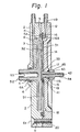
- Figure l is a diagram illustrating a liquid-fractionating apparatus according to one embodiment of the present invention
- Fig. 2 is a side view showing the right side half of the apparatus shown in Fig. l.
- a separating chamber l having a liquid-treating chamber and a separated liquid chamber therein comprises a cabin 2 composed of a polycarbonate and a cover l2 composed of a polycarbonate.
- a circular concave portion (liquid-treating chamber) 3 Formed on the right side face (in Fig. l) of the cabin 2 is a circular concave portion (liquid-treating chamber) 3, and an axial hole 4 is extended from the left side face and piercing through the concave portion 3 at the center thereof.
- An annular groove 5 for an O-ring is formed on the right side end face of the peripheral edge portion of the cabin 2 and a groove 6 for an O-ring is formed in the intermediate portion of the axial hole 4.
- Formed in the cabin 2 is a treated liquid discharge path 7 having one end open to the concave portion 3 in the vicinity of the axial hole 4 and the other end open to the outer peripheral face of the cabin 2.
- a fluid path 8 connected to the treated liquid discharge path 7 is formed on the top end (in Fig. l) of the concave portion 3.
- Formed in the peripheral edge portion of the cabin 2 are a plurality of bolt holes 9 piercing the left and right end faces.
- An annular groove l6 for a packing is formed on the left end face of the cover l2 on the outside of the concave portion l4.
- a notch l7 for an O-ring is formed on the right side end of the tubular insertion hole l5, a liquid-collecting groove l8 is formed in the outer peripheral edge of the concave portion l4 of the cover l2, and a separated component discharge path l9 having one end open to the liquid-collecting groove l8 and the other end open to the outer peripheral face of the cover l2 is formed.
- a plurality of bolt holes 20 piercing the left and right end faces are formed in the peripheral edge portion of the cover l2; the number of bolt holes 20 corresponding to the number of bolt holes 9.
- a substantially flat circular perforated plate 3l formed of stainless steel is secured on the left end face of the cover l2, to cover the concave portion l4, and a circular separating membrane 32 formed of a polycarbonate, which defines the separating wall surface, is arranged on the surface of the perforated plate 3l on the side opposite to the side facing the concave portion l4.
- the outer peripheral edges of the perforated plate 3l and separating membrane 32 are located on packing l6A inserted in the packing groove l6 of the cover l2, and the central portions of the perforated plate 3l and separating membrane 32 have a tubular insertion hole 33 and are located on the top l3 of the cover l2.
- a nozzle 44 having a flange 4l on one end, a starting liquid introduction path 42 piercing the central portion thereof, and a nut-screwing screw groove 43 on a part of the peripheral face is inserted in the tubular insertion holes l5 and 33 while pressing against the separating membrane 32 and perforated plate l4 by the flange 4l.
- the nozzle 44 is clamped to the cover l2 by a nut 45 screwed to the screw groove 43 while pressing an O-ring l7A inserted in the notch l7 for the O-ring, whereby the nozzle 44 is integrated with the cover l2.
- a rotary body (rotor) 5l consisting of a board-like cone formed of a polycarbonate, which is convex to the separating membrane 32, is contained within the concave portion 3 of the cabin 2, and the right side face (in Fig. l) of the rotary body 5l, i.e., the conical face, defines the shearing wall surface, and a rotation shaft 52 is extended from the left side face of the rotary body 5l and the rotation shaft 52 has on the top end thereof a connecting portion 53 for connection to a separately arranged rotation drive source (not shown).
- the rotation shaft 52 is inserted in the axial hole 4 of the cabin 2 and projected from the left side face of the cabin 2.
- the O-ring 6A fitted to the O-ring groove 6 is interposed between the rotation shaft 52 and the axial hole 4.
- the rotary body 5l is contained within the concave portion 3 of the cabin 2, and the left side face of the cover l2 to which the separating membrane 32, perforated plate 3l and nozzle 44 are secured, is engaged with and clamped to the right side face of the cabin 2 having the O-ring 5A inserted in the O-ring groove 5 by means of a bolt 6l inserted in the bolt holes 9 and 20, whereby the cabin 2 is integrated with the cover l2.
- the liquid treating chamber is defined by the concave portion 3 of the cabin 2 and the separating membrane 32.
- the space surrounded by the concave portion l4 of the cover l2 and the separating membrane 32 constitutes the separated component chamber.
- the shearing wall surface of the rotary body 5l is rotatably located at a certain distance from the separating wall surface of the separating membrane 32.
- This apparatus is designed as a means for separating plasma from blood.
- the angle between the plane rectangular to the axis of the rotation shaft 53 of the rotary body 5l and the conical face of the rotary body 5l is a specific angle within the range of from 0.5° to 5°.
- the diameter of the rotary body 5l is about 75 mm, and the distance in the axial direction between the top of the cone of the board-like portion of the rotary body 5l and the back face of this board-like portion is about 4 mm.
- the depth of the concave portion of the cabin 2 is about 7 mm and the diameter of the concave portion 3 is about 78 mm.
- the depth of the concave portion l4 of the cover l2 is about l mm and the diameter of the concave portion l4 is about 78 mm.
- the diameter of the separating chamber formed by integrating the cabin 2 with the cover l2 about ll2 mm and the thickness is about 22 mm.
- the thickness of the separating membrane 32 is about l0 ⁇ m, the average diameter of the pore is about 0.4 ⁇ m, the fraction of pores is about l3%, and the thickness of the perforated plate 3l is about 0.5 mm.
- the distance between the top end of the cone of the board-like portion of the rotary body 5l in the rotary body shown in Fig. l, the top end is cut and deformed but the top end referred to herein means the top end of a complete cone) and the separating wall surface of the separating membrane is about 0.l mm.
- the apparatus according to the present invention is used in the state shown in Fig. l, that is, the state where the rotation axis 52 is arranged in the horizontal direction, and a blood-collecting tube (not shown) connected to the vein of a rabbit (not shown) is connected to the nozzle 44 having the liquid introduction path 42. If necessary, a chemical, for example, an anti-coagulant for blood, is added at a point midway of the blood-collecting tube.
- Blood flowing into the liquid-treating chamber (concave portion) 3 from the liquid introduction path 42 of the nozzle 44 is filled and fluidized in the liquid-treating chamber (concave portion) 3 and is collected in an appropriate vessel (not shown) through a treated liquid discharge tube (not shown) connected in advance to the treated liquid discharge path 7.
- the gas in the liquid-treating chamber (concave portion) 3 is discharged into said tube through the fluid path 8 formed on the upper end of the liquid-treating chamber (concave portion) 3.
- the rotation shaft 52 coupled to an appropriate rotation drive source (not shown) by a one-touch system is rotated by this rotation drive source and blood continuously supplied to the center of the liquid-treating chamber (concave portion) 3 from the liquid introduction path 42 flows continuously between the shearing wall surface and the separating wall surface.
- a rotational movement is given to the blood by the rotation of the shearing wall surface and by this movement, a shear rate is produced to act on the blood and the separating wall surface.
- a plasma component is allowed to pass through the separating membrane 32 and then through holes of the perforated plate 3l, and the plasma component flows into the separated component chamber (annular concave portion) l4 and is continuously collected in an appropriate vessel (not shown) from a separated component discharge tube (not shown), connected beforehand to the separated component discharge path l9, through the separated component discharge path l9 and the tube.
- the blood in the liquid-treating chamber (concave portion) 3 that is, mainly the blood from which the plasma component has been separated, is passed through the treated liquid discharge path 7 and is continuously collected in an appropriate vessel (not shown) from a treated liquid discharge tube (not shown) connected beforehand to the treated liquid discharge path 7.
- the main treatment conditions are as described below. That is, the feed rate of blood to the liquid introduction path 42 is about 50 ml/min, and the rotation speed of the rotary body 5l is adjusted to about 3000 rpm.
- the shearing wall surface is a conical surface which is convex to the separating wall surface and the separating wall surface is a circular plane.
- other combinations of the shearing wall surface and the separating wall surface can be adopted.
- a combination of the shearing wall surface which is a circular plane and the separating wall surface which is convex to the shearing wall surface a combination of the separating wall surface which is convex to the shearing wall surface and the shearing wall surface which is convex to the separating wall surface
- a combination of the shearing wall surface which is a circular plane and the separating wall surface which is a circular plane and a slight modification thereof.
- the penultimate combination is not preferred where a strict uniformity of the shear rate at the positions in the radial direction of the shearing wall surface is required.
- the treating mechanism comprises a pair of one separating wall surface and one shearing wall surface.
- a plurality of pairs of these treating wall surfaces may be disposed in the apparatus.
- An embodiment comprising two pairs of the treating wall surfaces is illustrated in Figs. 3 and 4.
- FIG. 3 is a diagram illustrating the longitudinal section of another embodiment of the apparatus of the present invention.
- the apparatus comprises a substantially cylindrical case body 7l having the upper and lower ends thereof and having a height smaller than the diameter thereof, where the interior of the case body 7l is divided into three chambers by two separating membranes 72 and 73. Namely, a first liquid-treating chamber 74, a separated component chamber 75, and a second liquid-treating chamber 76 are formed in order from the top (Fig. 3).
- a disc-like conical rotary body 77 is rotatably attached to and supported on the case body 7l in the first liquid-treating chamber 74 and a magnet 78 is attached to the top face (Fig. 3) of the rotary body 77.
- a magnet 80 is attached to a rotation shaft 79 to confront the magnet 78.
- the rotation shaft 79 By rotating the rotation shaft 79 by an appropriate rotation drive source (not shown), the rotation of the magnet 80 is transmitted to the magnet 78 to rotate the rotary body 77 in the first liquid-treating chamber 74.
- a disc-like conical rotary body 8l is rotatably attached to and supported on the case body 7l, and a magnet 82 is attached to the lower face (in Fig. 3) of the rotary body 8l.
- a magnet 84 is attached to a rotation shaft 83 to confront the magnet 82.
- First and second liquid introduction paths 85 and 86 are connected to one side of each of the first and second liquid-treating chambers 74 and 76, and first and second treated liquid discharge paths 87 and 88 are connected to the other side of each of the first and second liquid-treating chambers 74 and 76.
- the structural elements represented by the same names as in the apparatus shown in Figs. l and 2 have substantially the same structure and material as the structural elements illustrated in Figs. l and 2. Liquids to be supplied to the first liquid introduction path 85 and second liquid introduction path 86 in the apparatus shown in Fig. 3 may be the same or different.
- Figure 4 is a diagram illustrating the longitudinal section of an apparatus according to still another embodiment of the present invention.
- the apparatus as a whole comprises a cylindrical case body 9l having closed at the upper and lower ends thereof and a height smaller than the diameter thereof, and the interior of the case body 9l is divided into three chambers by two separating membranes 92 and 93. Namely, a first separated component chamber 94, a liquid-treating chamber 95, and a second separated component chamber 96 are formed in order from the top (in Fig. 4).
- a conical rotary body 97 having conical portions on the top and bottom of a disc is rotatably attached to and supported on the case body 9l, and a rotation shaft 98 secured to the top of the upper cone of the rotary body 97 is rotatably fitted in an axial hole 99 formed to pierce the first separated component chamber 94 and is projected outside the case body 9l to be engaged with an appropriate rotating drive source (not shown).
- a liquid introduction path l00 and a treated liquid discharge path l0l are connected to the liquid-treating chamber 95, and a first separated component discharge path l02 and a separated component discharge path l03 are connected to the first separated component chamber 94 and the second separated component chamber 96, respectively.
- the structural elements represented by the same names as in the apparatus shown in Figs. l and 2 have substantially the same structure and are substantially formed of the same material as in the apparatus shown in Figs. l and 2.
- the separating members 92 and 93 defining the first and second separated component chambers 94 and 96 may have the same or different structure and material.
- the angle between the top face of the conical rotary body 97 and the horizontal plane of the cone may be the same or different from the angle between the bottom face of the conical rotary body 97 and the horizontal plane of the cone.
- FIG. 5 is a systematic diagram illustrating an example of the the blood-collecting system in which the apparatus of the present invention is utilized.
- the apparatus shown in Fig. l is used as a means for fractionating a liquid (blood).
- This fractionating apparatus comprises a separating chamber l, as shown in Fig. l, and in this separating chamber l, there are disposed a rotation shaft 52, a liquid (blood) introduction path 42, a treated liquid (treated blood) discharge path 7, and a separated component (mainly a plasma component) discharge path l9, as shown in Fig. l.
- a blood flow path lll is connected to the blood introduction path 42 and a pump (roller pump) A is interposed in the blood flow path lll.
- a treated blood flow path ll3 is connected to the treated blood discharge path 7 and a treated blood-containing bag B is connected to the end of the path ll3.
- a clamp mechanism C is interposed at a point midway of the path ll3 and a pressure gauge D is arranged to extend from the clamp mechanism C toward the separating chamber l.
- a plasma component flow path ll4 is connected to the plasma component discharge path l9, and a plasma component-containing bag E is connected to the end of the path ll4.
- the liquid-treating chamber (blood chamber) in the separating chamber l is compressed by the pump A to impart a pressure to the separating membrane in the separating chamber l.
- the plasma component is fractionated and is stored in the plasma-containing bag E.
- the pressure in the separating chamber l is detected by the pressure gauge D.
- a control system (not shown) for automatically adjusting the opening degree of the clamp C or the rotation number of the pump A according to the detecting signal of the pressure gauge D may be disposed to inspect the fractionating operation in the separating chamber and simultaneously adjust the fractionating operation automatically. Note, if a pump F (indicated by a dotted line in parallel to the clamp C in Fig.
- the pressure difference between the liquid-treating chamber and the separated component chamber is about l0 to about 50 mmHg.
- Figure 6 is a schematic diagram illustrating the longitudinal section of an apparatus according to still another embodiment of the present invention
- Fig. 7 is a schematic diagram illustrating the longitudinal section of an apparatus according to a further embodiment of the present invention.
- a separating chamber case body l2l having a thin cylindrical shape and having a liquid-treating chamber and a separated liquid chamber in the interior thereof is formed of a polycarbonate.
- a columnar liquid-treating chamber l22 is closed in the state where the liquid is filled and circulated.
- a part (upper wall surface in Fig. 6) of the inner wall surface of the liquid-treating chamber l22 is a shearing wall surface l23 having a certain area, and in the present embodiment, this shearing wall surface has a conical shape.
- One end of a liquid introduction path l24 connected to the outside of the separating chamber case body l2l is open to the top of the conical shearing wall surface l23 of the liquid-treating chamber l22, and one end of a liquid discharge path l25 connected to the outside of the separating chamber case body l2l is open to the peripheral side wall of the liquid-treating chamber l22.
- a rotation shaft-fitting hole l26 connected to the outside of the separating chamber case body l2l is open to the lower wall surface of the liquid-treating chamber l22.
- a board-like rotary body l3l is contained in the interior of the liquid-treating chamber l22, and this rotary body l3l comprises a circular plate-like member l32 formed of a polycarbonate, a separating member l33 attached to the top face of the plate-like member l32 to cover the plate-like member l32, and a polycarbonate tube l34 open to the center of the lower face of the concave portion of the plate-like member l32.
- the separating member l33 comprises a substantially plane perforated plate l35 formed of stainless steel and a separating membrane l36 of a polycarbonate mounted on the perforated plate l35.
- the concave portion of the plate-like member l32 covered by the separating member l33 defines a separated component chamber l37, and a separating wall surface is defined by the top surface of the separating membrane l36 confronting the shearing wall surface l23.
- the tube l34 forms a separated component discharge path l38.
- a rotation driving mechanism l4l is engaged with the portion of the tube l34 forming a part of the rotary body l3l, which is located outside of the separating chamber case body l2l.
- This apparatus is especially designed as a means for separating plasma from blood.
- the angle between the plane rectangular to the central axis of the cone forming the shearing wall surface l23 and the conical surface is a specific angle within the range of from 0.5° to 5°.
- the diameter of the liquid-treating chamber l22 is about 78 mm
- the height of the cone forming the shearing wall surface l23 is about 4 mm
- the depth of the concave portion of the rotary body l3l is about l mm
- the outer diameter of the rotary body l3l is about 75 mm.
- the diameter of the separating member l33 is about ll2 mm and the thickness is about 22 mm.
- the thickness of the separating membrane l36 is about l0 ⁇ m, the average diameter of the pores is about 0.4 ⁇ m, and the fraction of pores is about l3%.
- the thickness of the perforated plate l35 is about 0.5 mm.
- the distance between the top end of the cone forming the shearing wall surface l23 of the liquid-treating chamber l22 and the separating wall surface of the separating membrane l36 is about 0.l mm.
- a blood-collecting tube (not shown) inserted into the vein of a rabbit (not shown) is connected to a liquid introduction path l24. If necessary, a chemical, for example, an anti-coagulant for blood, is added in the midway of the blood-collecting tube. Blood introduced into the liquid-treating chamber l22 from the liquid introduction path l24 is filled and fluidized in the liquid-treating chamber l22 and is collected in an appropriate vessel (not shown) through a treated liquid discharge tube (not shown) connected beforehand to the treated liquid discharge path l25.
- the rotary member l3l is rotated by the rotating driving mechanism l4l and blood continuously supplied to the center of the liquid-treating chamber l22 from the liquid introduction path l24 continuously flows between the shearing wall surface and the separating wall surface, and a rotary movement is given to the blood by the rotating separating wall surface and by this rotary movement, a shear stress is generated between the blood and the separating wall surface.
- the plasma component Under the action of this shear stress, the plasma component is allowed to pass through the separating membrane l36 and holes of the perforated plate l35 and the plasma component flows in the separated component chamber l37, passes through the separated component discharge path l38 and is continuously collected in an appropriate vessel (not shown) arranged beforehand on the extrusion opening of the separated component discharge path l38.
- the blood in the liquid-treating chamber l22 that is, mainly the blood from which the plasma component has been separated, passes through the treated liquid discharge path l25 and is continuously collected in an appropriate vessel (not shown) from a treated liquid discharge tube (not shown) connected beforehand to the treated liquid discharge path l25.
- the main operating conditions are as described below. More specifically, the feed rate of the blood to the liquid introduction path l24 is about 50 ml/min, and the rotation speed of the rotary member l3l is about 3000 rpm.
- the above-mentioned apparatus is illustrated in the state where the rotation shaft (central axis) is vertical.
- the apparatus may be used in the state where the rotation shaft is horizontal, or a gas discharge hole to be used at the start of the operation may be separately formed.
- the shearing wall surface is a conical surface which is convex to the separating surface and the separating wall surface is a circular plane surface, but other combinations may be adopted.
- a combination of the shearing wall surface which is a circular plane surface and the separating wall surface which is a conical surface convex to the separating wall surface a combination of the shearing wall surface which is a conical surface convex to the separating wall surface and the separating wall surface which is a conical surface convex to the shearing wall surface, a combination of the shearing wall surface which is a circular plane surface and the separating wall surface which is a circular plane surface, and a slight modification thereof.
- the penultimate combination is not preferred where a strict uniformity of the shear stress at the positions in the radial direction of the shearing wall surface is required.
- the treating mechanism comprising a pair of one separating wall surface and one shearing wall surface is disposed in the apparatus of the present embodiment, and a plurality of pairs of these treating wall surfaces may be disposed in the apparatus.
- An apparatus comprising four pairs of the treating wall surfaces is illustrated in Fig. 7.
- Fig. 7 is a schematic diagram illustrating the longitudinal section of an apparatus according to a further embodiment of the present invention.
- the apparatus as a whole comprises a cylindrical case body l5l closed at the top and bottom and having a height smaller than the diameter thereof.
- a first liquid-treating chamber l52 and a second liquid-treating chamber l53 are formed in the interior of the case body l5l.
- Conical wall surfaces l54 and l55 are formed on the top and bottom faces of the first liquid-treating chamber l52, and conical wall surfaces l56 and l57 are similarly formed on the top and bottom faces of the second liquid-treating chambers l53.
- wall surfaces l54, l55, l56, and l57 form shearing wall surfaces.
- rotation shaft-fitting holes l58 and l59 are formed on the upper and lower faces of the case body l5l, and a fluid circulation hole l60 is formed on the wall surface of the central portion.
- a liquid introduction path l6l connected to the first liquid-treating chamber l52 and a treated liquid discharge path l62 connected to the second liquid-treating chamber l53.
- a first disc-like case rotary body l7l and a second disc-like case rotary body l72 are arranged in the first liquid-treating chamber l52 and the second liquid-treating chamber l53, respectively.
- Separating members l73, l74, l75, and l76 are arranged on the upper and lower faces of the first and second case rotary bodies l7l and l72, within which a separated component chamber is formed, and the outer side faces of the separated component chamber form separating wall surfaces.
- a rotation shaft l77 is secured to the central portion of the upper face of the first case rotary body l7l, and the rotation shaft l77 is rotatably fitted to the rotation shaft-fitting hole l58 outside of the case body l5l and is engaged with a rotation driving mechanism l8l through the fitting hole l58.
- a tube l78 is secured to the central portion of the lower face of the first case rotary body l7l, and this tube l78 extends downward, pierces the fluid circulation hole l60, is secured to the second case rotary body l72, pierces the rotary body l72, is rotatably fitted to the rotation shaft-fitting hole l59 outside of the case body l5l, and pierces the fitting hole l59.
- the inner tube path of the tube l78 forms a separated component discharge path, and this tube path is opened and connected to the separated component chamber of the first case rotary body l7l and the separated component chamber of the second case rotary body l72.
- the structural elements of the apparatus of the present embodiment having the same names as in the apparatus shown in Fig. 6 have substantially the same structure and material as those of the apparatus shown in Fig. 6.
- the separating and members l73, l74, l75, and l76 may have the same or different in the structure and material.
- the apex angles of the cones of the wall surfaces l54, l55, l56, and l57 may be the same or different.
- the liquid separating membrane is used, and by a motion imparted to the liquid by the rotary body, a shear rate is produced between the liquid separating membrane and the liquid to separate a predetermined component from the liquid. Accordingly, the area of the separating membrane can be drastically reduced compared with the area of the separating membrane in the above-mentioned conventional apparatus fabricated by using hollow fibers (in the first conventional technique).
- a membrane area of about l000 to about 3000 cm2 is necessary in the conventional apparatus, but in the apparatus of the present invention, a membrane area of about 50 cm2 is sufficient because a shear rate of about 5000 to about l0000 sec ⁇ 1 is produced.
- the size of the liquid-fractionating apparatus can be surprisingly diminished by adopting a structure in which a disc-like rotary body is used as the rotary body for producing a shear rate and is rotated in a substantially closed small concave portion (liquid-treating chamber), or a disc-like rotary body having a separating wall surface is rotated in the liquid-treating chamber, and a liquid introduction path and a treated liquid discharge path are connected to this substantially closed small liquid-treating chamber so that the liquid to be treated is continuously introduced into the liquid-treating chamber and the treated liquid is continuously discharged from the liquid-treating chamber. Accordingly, an economically advantageous, disposable liquid-fractionating apparatus can be provided for the first time, according to the present invention.
- the apparatus of the present invention sufficient performance can be attained even if the diameter of the apparatus is about l0 cm and the thickness of the apparatus is about 2 cm. This effect is especially important when the apparatus is used as a plasma-collecting apparatus in which the quantity of blood collected from the human body should be reduce to a level as low as possible and the separating chamber l should be disposable to prevent infection.
Landscapes
- Chemical & Material Sciences (AREA)
- Chemical Kinetics & Catalysis (AREA)
- Health & Medical Sciences (AREA)
- Heart & Thoracic Surgery (AREA)
- Hematology (AREA)
- Engineering & Computer Science (AREA)
- Anesthesiology (AREA)
- Biomedical Technology (AREA)
- Vascular Medicine (AREA)
- Life Sciences & Earth Sciences (AREA)
- Animal Behavior & Ethology (AREA)
- General Health & Medical Sciences (AREA)
- Public Health (AREA)
- Veterinary Medicine (AREA)
- External Artificial Organs (AREA)
- Investigating Or Analysing Biological Materials (AREA)
- Centrifugal Separators (AREA)
Applications Claiming Priority (2)
| Application Number | Priority Date | Filing Date | Title |
|---|---|---|---|
| JP61060780A JPS62217973A (ja) | 1986-03-20 | 1986-03-20 | 液体を分別する装置 |
| JP60780/86 | 1986-03-20 |
Publications (3)
| Publication Number | Publication Date |
|---|---|
| EP0238335A2 true EP0238335A2 (fr) | 1987-09-23 |
| EP0238335A3 EP0238335A3 (en) | 1988-01-07 |
| EP0238335B1 EP0238335B1 (fr) | 1991-07-24 |
Family
ID=13152144
Family Applications (1)
| Application Number | Title | Priority Date | Filing Date |
|---|---|---|---|
| EP87302368A Expired - Lifetime EP0238335B1 (fr) | 1986-03-20 | 1987-03-19 | Appareil pour plasmaphérèse |
Country Status (10)
| Country | Link |
|---|---|
| US (1) | US4968600A (fr) |
| EP (1) | EP0238335B1 (fr) |
| JP (1) | JPS62217973A (fr) |
| KR (1) | KR910005292B1 (fr) |
| CN (1) | CN1009709B (fr) |
| AU (1) | AU587114B2 (fr) |
| CA (1) | CA1334395C (fr) |
| DE (1) | DE3771535D1 (fr) |
| ES (1) | ES2023894B3 (fr) |
| IN (1) | IN170744B (fr) |
Cited By (8)
| Publication number | Priority date | Publication date | Assignee | Title |
|---|---|---|---|---|
| WO1990000069A1 (fr) * | 1988-06-29 | 1990-01-11 | Biodynamics, Inc. | Procede et appareil d'autotransfusion sanguine |
| EP0560281A1 (fr) * | 1992-03-10 | 1993-09-15 | Pall Corporation | Séparateur à filtre dynamique |
| EP0815927A2 (fr) * | 1996-06-28 | 1998-01-07 | Gesellschaft für Biotechnologische Forschung mbH (GBF) | Dispositif de séparation de cellules et de purification de produits intégrés |
| WO2000007701A1 (fr) * | 1998-08-03 | 2000-02-17 | Plasmaselect Aktiengesellschaft | Dispositif et procede de filtration |
| DE102005023152A1 (de) * | 2004-12-21 | 2006-06-22 | Rwth Aachen | Oxygenator zum Gasaustausch |
| WO2010072237A1 (fr) * | 2008-12-23 | 2010-07-01 | Kmpt Ag | Procédé et dispositif pour traiter des fluides |
| WO2012065820A1 (fr) * | 2010-11-15 | 2012-05-24 | Voith Patent Gmbh | Filtre à disques |
| EP2590725A4 (fr) * | 2010-07-07 | 2016-11-23 | Fenwal Inc | Séparateurs de fluide employant un palier fluidique |
Families Citing this family (22)
| Publication number | Priority date | Publication date | Assignee | Title |
|---|---|---|---|---|
| JPH0624595B2 (ja) * | 1988-05-31 | 1994-04-06 | 工業技術院長 | 血液分離装置 |
| US5679249A (en) * | 1991-12-24 | 1997-10-21 | Pall Corporation | Dynamic filter system |
| US5298016A (en) * | 1992-03-02 | 1994-03-29 | Advanced Haemotechnologies | Apparatus for separating plasma and other wastes from blood |
| US5318376A (en) * | 1992-12-07 | 1994-06-07 | Prescott Sr Everett J | Manhole frame |
| US6117322A (en) * | 1993-06-23 | 2000-09-12 | Pall Corporation | Dynamic filter system |
| US6692702B1 (en) | 2000-07-07 | 2004-02-17 | Coulter International Corp. | Apparatus for biological sample preparation and analysis |
| AU2002366538A1 (en) * | 2001-12-13 | 2003-06-23 | Foss Analytical A/S | Method and device for extraction and filtration of a sample |
| US9144583B2 (en) | 2002-03-29 | 2015-09-29 | Tissue Genesis, Inc. | Cell separation apparatus and methods of use |
| EP2359689B1 (fr) | 2002-09-27 | 2015-08-26 | The General Hospital Corporation | Dispositif microfluidique pour la séparation de cellules et usage du dispositif |
| US20070196820A1 (en) | 2005-04-05 | 2007-08-23 | Ravi Kapur | Devices and methods for enrichment and alteration of cells and other particles |
| US8921102B2 (en) | 2005-07-29 | 2014-12-30 | Gpb Scientific, Llc | Devices and methods for enrichment and alteration of circulating tumor cells and other particles |
| CN100398451C (zh) * | 2006-01-16 | 2008-07-02 | 王雄鹰 | 一种结合陶瓷生产从石煤提钒并根治污染的方法 |
| US11174458B2 (en) | 2007-04-23 | 2021-11-16 | Koligo Therapeutics, Inc. | Cell separation apparatus and methods of use |
| RU2013148149A (ru) * | 2011-05-02 | 2015-06-10 | Технише Университейт Эйндховен | Устройство для многофазного и однофазного контактирования |
| CN103509717B (zh) * | 2012-06-21 | 2016-01-20 | 中国农业机械化科学研究院 | 一种动态流膜浓缩装置 |
| US8900169B2 (en) | 2013-03-15 | 2014-12-02 | Tbi Innovations, Llc | Methods and devices to reduce the likelihood of injury from concussive or blast forces |
| CN103551038B (zh) * | 2013-11-15 | 2015-03-11 | 周小山 | 膜分离装置 |
| AU2016355540B2 (en) | 2015-11-16 | 2021-02-18 | Q30 Sports Science, Llc | Traumatic brain injury protection devices |
| EP3422959A4 (fr) | 2016-03-02 | 2019-11-27 | Q30 Sports Science, LLC | Procédés et dispositifs permettant de réduire les effets préjudiciables des forces de commotion ou d'explosion sur un sujet |
| WO2017171638A1 (fr) * | 2016-03-28 | 2017-10-05 | Nanyang Technological University | Filtration à membrane à écoulement transversal au moyen d'un canal de filtration incliné |
| CN107522192B (zh) * | 2017-07-11 | 2019-08-16 | 南通大学 | 连续流立式平面型液相剪切方法 |
| TWI644883B (zh) * | 2017-10-03 | 2018-12-21 | 淡江大學 | 多孔性薄膜的製備方法、乳化元件及乳化裝置 |
Citations (5)
| Publication number | Priority date | Publication date | Assignee | Title |
|---|---|---|---|---|
| US3883434A (en) * | 1972-10-25 | 1975-05-13 | Atomic Energy Authority Uk | Reverse osmosis apparatus |
| DE2812042A1 (de) * | 1978-03-20 | 1979-10-31 | Harold Hebding | Trennanlage zum abtrennen von stoffen aus emulsionen |
| EP0083005A2 (fr) * | 1981-12-24 | 1983-07-06 | VEB Chemieanlagenbaukombinat Leipzig-Grimma | Dispositif de séparation à membrane plate |
| EP0112152A2 (fr) * | 1982-12-13 | 1984-06-27 | McLaughlin, William Francis | Système et procédé de fractionnement du sang |
| WO1985002783A1 (fr) * | 1983-12-20 | 1985-07-04 | Membrex, Inc. | Appareil et procede de filtrage |
Family Cites Families (11)
| Publication number | Priority date | Publication date | Assignee | Title |
|---|---|---|---|---|
| US2734015A (en) * | 1956-02-07 | Process for the manufacture of hydrolyzed adrenocorticotrophin | ||
| US2362231A (en) * | 1942-07-27 | 1944-11-07 | Oliver United Filters Inc | Filter |
| AU516046B2 (en) * | 1975-10-08 | 1981-05-14 | Baxter Travenol Laboratories Inc. | Dialyzer construction |
| US4069151A (en) * | 1976-03-31 | 1978-01-17 | C. R. Bard, Inc. | Thin polycarbonate membranes for use in hemodialysis |
| US4071444A (en) * | 1976-10-12 | 1978-01-31 | Purdue Research Foundation | Portable chemical reactor for use as an artificial kidney |
| US4191182A (en) * | 1977-09-23 | 1980-03-04 | Hemotherapy Inc. | Method and apparatus for continuous plasmaphersis |
| AU517953B2 (en) * | 1980-01-29 | 1981-09-03 | Baxter Travenol Laboratories Inc. | Plate dialyzer |
| JPS57121956A (en) * | 1981-01-22 | 1982-07-29 | Nissan Motor Co Ltd | Anti-skid controller |
| JPS58155758A (ja) * | 1982-03-10 | 1983-09-16 | Matsushita Electric Ind Co Ltd | 光電変換素子およびその製造方法 |
| US4668394A (en) * | 1983-01-10 | 1987-05-26 | Mcneilab, Inc. | Filtration media and supporting frame |
| US4713176A (en) * | 1985-04-12 | 1987-12-15 | Hemascience Laboratories, Inc. | Plasmapheresis system and method |
-
1986
- 1986-03-20 JP JP61060780A patent/JPS62217973A/ja active Granted
-
1987
- 1987-03-12 CA CA000531922A patent/CA1334395C/fr not_active Expired - Fee Related
- 1987-03-13 US US07/025,338 patent/US4968600A/en not_active Expired - Lifetime
- 1987-03-17 IN IN224/DEL/87A patent/IN170744B/en unknown
- 1987-03-19 ES ES87302368T patent/ES2023894B3/es not_active Expired - Lifetime
- 1987-03-19 AU AU70185/87A patent/AU587114B2/en not_active Ceased
- 1987-03-19 EP EP87302368A patent/EP0238335B1/fr not_active Expired - Lifetime
- 1987-03-19 DE DE8787302368T patent/DE3771535D1/de not_active Expired - Fee Related
- 1987-03-20 CN CN87103201A patent/CN1009709B/zh not_active Expired
- 1987-03-20 KR KR1019870002567A patent/KR910005292B1/ko not_active IP Right Cessation
Patent Citations (5)
| Publication number | Priority date | Publication date | Assignee | Title |
|---|---|---|---|---|
| US3883434A (en) * | 1972-10-25 | 1975-05-13 | Atomic Energy Authority Uk | Reverse osmosis apparatus |
| DE2812042A1 (de) * | 1978-03-20 | 1979-10-31 | Harold Hebding | Trennanlage zum abtrennen von stoffen aus emulsionen |
| EP0083005A2 (fr) * | 1981-12-24 | 1983-07-06 | VEB Chemieanlagenbaukombinat Leipzig-Grimma | Dispositif de séparation à membrane plate |
| EP0112152A2 (fr) * | 1982-12-13 | 1984-06-27 | McLaughlin, William Francis | Système et procédé de fractionnement du sang |
| WO1985002783A1 (fr) * | 1983-12-20 | 1985-07-04 | Membrex, Inc. | Appareil et procede de filtrage |
Non-Patent Citations (1)
| Title |
|---|
| Y. NOSE et al.: "Plasmapheresis", 1983, pages 135-143, Raven Press, New York, US; * |
Cited By (11)
| Publication number | Priority date | Publication date | Assignee | Title |
|---|---|---|---|---|
| WO1990000069A1 (fr) * | 1988-06-29 | 1990-01-11 | Biodynamics, Inc. | Procede et appareil d'autotransfusion sanguine |
| US4935002A (en) * | 1988-06-29 | 1990-06-19 | Biodynamics, Inc. | Apparatus and method for the autotransfusion of blood |
| EP0560281A1 (fr) * | 1992-03-10 | 1993-09-15 | Pall Corporation | Séparateur à filtre dynamique |
| EP0815927A2 (fr) * | 1996-06-28 | 1998-01-07 | Gesellschaft für Biotechnologische Forschung mbH (GBF) | Dispositif de séparation de cellules et de purification de produits intégrés |
| EP0815927A3 (fr) * | 1996-06-28 | 1998-04-15 | Gesellschaft für Biotechnologische Forschung mbH (GBF) | Dispositif de séparation de cellules et de purification de produits intégrés |
| WO2000007701A1 (fr) * | 1998-08-03 | 2000-02-17 | Plasmaselect Aktiengesellschaft | Dispositif et procede de filtration |
| US6508943B2 (en) | 1998-08-03 | 2003-01-21 | Plasmaselect Aktiengesellschaft | Filtering device and a filtering method |
| DE102005023152A1 (de) * | 2004-12-21 | 2006-06-22 | Rwth Aachen | Oxygenator zum Gasaustausch |
| WO2010072237A1 (fr) * | 2008-12-23 | 2010-07-01 | Kmpt Ag | Procédé et dispositif pour traiter des fluides |
| EP2590725A4 (fr) * | 2010-07-07 | 2016-11-23 | Fenwal Inc | Séparateurs de fluide employant un palier fluidique |
| WO2012065820A1 (fr) * | 2010-11-15 | 2012-05-24 | Voith Patent Gmbh | Filtre à disques |
Also Published As
| Publication number | Publication date |
|---|---|
| JPH044908B2 (fr) | 1992-01-29 |
| JPS62217973A (ja) | 1987-09-25 |
| IN170744B (fr) | 1992-05-09 |
| KR910005292B1 (ko) | 1991-07-24 |
| AU587114B2 (en) | 1989-08-03 |
| CN1009709B (zh) | 1990-09-26 |
| ES2023894B3 (es) | 1992-02-16 |
| EP0238335A3 (en) | 1988-01-07 |
| EP0238335B1 (fr) | 1991-07-24 |
| AU7018587A (en) | 1987-09-24 |
| CN87103201A (zh) | 1987-12-16 |
| DE3771535D1 (de) | 1991-08-29 |
| KR870008590A (ko) | 1987-10-19 |
| CA1334395C (fr) | 1995-02-14 |
| US4968600A (en) | 1990-11-06 |
Similar Documents
| Publication | Publication Date | Title |
|---|---|---|
| EP0238335A2 (fr) | Appareil pour plasmaphérèse | |
| US5464534A (en) | Blood fractionation system and method | |
| JP6398104B2 (ja) | 遠心機デバイス、遠心機、および遠心機を含む検査キット | |
| EP0877648B1 (fr) | Systeme de filtrage des fluides medicaux et biologiques | |
| CA1258053A (fr) | Systeme et methode pour le fractionnement du sang | |
| CA1267610A (fr) | Methode et dispositif de separation du plasma sanguin | |
| US4600507A (en) | Filter device for liquids | |
| US6113782A (en) | Potting of tubular bundles in housing | |
| EP0194271B1 (fr) | Systeme d'hemapherese | |
| CA1296693C (fr) | Appareil et methode de separation des phrases | |
| US4421503A (en) | Fluid processing centrifuge and apparatus thereof | |
| EP0315252B1 (fr) | Séparateur pour liquides contenant des cellules | |
| EP0424439B1 (fr) | Procede et appareil d'autotransfusion sanguine | |
| US4816162A (en) | Process and device for the selective separation of pathological and/or toxic species or plasma | |
| US4647376A (en) | Device for removing the liquid phase from a suspension | |
| US4228015A (en) | Plasma treatment apparatus | |
| EP4095226A1 (fr) | Appareil de séparation de cellules pour bioréacteur | |
| US5045207A (en) | Multi-concentration disposable liquid concentrating device | |
| GB2173711A (en) | Filter device | |
| EP0070159B1 (fr) | Appareil centrifuge et méthodes pour la séparation de fluides en leurs composants | |
| JPH01155265A (ja) | 液体を分別する装置 | |
| CN117920473A (zh) | 富血小板血浆制备器 | |
| JPH023464B2 (fr) | ||
| JPH01155266A (ja) | 液体を分別する装置 | |
| JPH04281829A (ja) | 回転円板型分離装置 |
Legal Events
| Date | Code | Title | Description |
|---|---|---|---|
| PUAI | Public reference made under article 153(3) epc to a published international application that has entered the european phase |
Free format text: ORIGINAL CODE: 0009012 |
|
| AK | Designated contracting states |
Kind code of ref document: A2 Designated state(s): CH DE ES FR GB IT LI |
|
| PUAL | Search report despatched |
Free format text: ORIGINAL CODE: 0009013 |
|
| AK | Designated contracting states |
Kind code of ref document: A3 Designated state(s): CH DE ES FR GB IT LI |
|
| 17P | Request for examination filed |
Effective date: 19880421 |
|
| 17Q | First examination report despatched |
Effective date: 19891222 |
|
| ITF | It: translation for a ep patent filed |
Owner name: INTERPATENT ST.TECN. BREV. |
|
| GRAA | (expected) grant |
Free format text: ORIGINAL CODE: 0009210 |
|
| AK | Designated contracting states |
Kind code of ref document: B1 Designated state(s): CH DE ES FR GB IT LI |
|
| REF | Corresponds to: |
Ref document number: 3771535 Country of ref document: DE Date of ref document: 19910829 |
|
| ET | Fr: translation filed | ||
| REG | Reference to a national code |
Ref country code: ES Ref legal event code: FG2A Ref document number: 2023894 Country of ref document: ES Kind code of ref document: B3 |
|
| PLBE | No opposition filed within time limit |
Free format text: ORIGINAL CODE: 0009261 |
|
| STAA | Information on the status of an ep patent application or granted ep patent |
Free format text: STATUS: NO OPPOSITION FILED WITHIN TIME LIMIT |
|
| 26N | No opposition filed | ||
| REG | Reference to a national code |
Ref country code: GB Ref legal event code: IF02 |
|
| PGFP | Annual fee paid to national office [announced via postgrant information from national office to epo] |
Ref country code: FR Payment date: 20030310 Year of fee payment: 17 |
|
| PGFP | Annual fee paid to national office [announced via postgrant information from national office to epo] |
Ref country code: GB Payment date: 20030319 Year of fee payment: 17 |
|
| PGFP | Annual fee paid to national office [announced via postgrant information from national office to epo] |
Ref country code: DE Payment date: 20030327 Year of fee payment: 17 |
|
| PGFP | Annual fee paid to national office [announced via postgrant information from national office to epo] |
Ref country code: ES Payment date: 20030328 Year of fee payment: 17 |
|
| PGFP | Annual fee paid to national office [announced via postgrant information from national office to epo] |
Ref country code: CH Payment date: 20030331 Year of fee payment: 17 |
|
| PG25 | Lapsed in a contracting state [announced via postgrant information from national office to epo] |
Ref country code: GB Free format text: LAPSE BECAUSE OF NON-PAYMENT OF DUE FEES Effective date: 20040319 |
|
| PG25 | Lapsed in a contracting state [announced via postgrant information from national office to epo] |
Ref country code: ES Free format text: LAPSE BECAUSE OF NON-PAYMENT OF DUE FEES Effective date: 20040320 |
|
| PG25 | Lapsed in a contracting state [announced via postgrant information from national office to epo] |
Ref country code: LI Free format text: LAPSE BECAUSE OF NON-PAYMENT OF DUE FEES Effective date: 20040331 Ref country code: CH Free format text: LAPSE BECAUSE OF NON-PAYMENT OF DUE FEES Effective date: 20040331 |
|
| PG25 | Lapsed in a contracting state [announced via postgrant information from national office to epo] |
Ref country code: DE Free format text: LAPSE BECAUSE OF NON-PAYMENT OF DUE FEES Effective date: 20041001 |
|
| GBPC | Gb: european patent ceased through non-payment of renewal fee |
Effective date: 20040319 |
|
| REG | Reference to a national code |
Ref country code: CH Ref legal event code: PL |
|
| PG25 | Lapsed in a contracting state [announced via postgrant information from national office to epo] |
Ref country code: FR Free format text: LAPSE BECAUSE OF NON-PAYMENT OF DUE FEES Effective date: 20041130 |
|
| REG | Reference to a national code |
Ref country code: FR Ref legal event code: ST |
|
| PG25 | Lapsed in a contracting state [announced via postgrant information from national office to epo] |
Ref country code: IT Free format text: LAPSE BECAUSE OF NON-PAYMENT OF DUE FEES;WARNING: LAPSES OF ITALIAN PATENTS WITH EFFECTIVE DATE BEFORE 2007 MAY HAVE OCCURRED AT ANY TIME BEFORE 2007. THE CORRECT EFFECTIVE DATE MAY BE DIFFERENT FROM THE ONE RECORDED. Effective date: 20050319 |
|
| REG | Reference to a national code |
Ref country code: ES Ref legal event code: FD2A Effective date: 20040320 |