EP0237682B1 - Control system for optical information reproducing apparatus - Google Patents
Control system for optical information reproducing apparatus Download PDFInfo
- Publication number
- EP0237682B1 EP0237682B1 EP86310026A EP86310026A EP0237682B1 EP 0237682 B1 EP0237682 B1 EP 0237682B1 EP 86310026 A EP86310026 A EP 86310026A EP 86310026 A EP86310026 A EP 86310026A EP 0237682 B1 EP0237682 B1 EP 0237682B1
- Authority
- EP
- European Patent Office
- Prior art keywords
- signal
- power supply
- circuit
- control system
- control signal
- Prior art date
- Legal status (The legal status is an assumption and is not a legal conclusion. Google has not performed a legal analysis and makes no representation as to the accuracy of the status listed.)
- Expired - Lifetime
Links
Images


Classifications
-
- G—PHYSICS
- G11—INFORMATION STORAGE
- G11B—INFORMATION STORAGE BASED ON RELATIVE MOVEMENT BETWEEN RECORD CARRIER AND TRANSDUCER
- G11B19/00—Driving, starting, stopping record carriers not specifically of filamentary or web form, or of supports therefor; Control thereof; Control of operating function ; Driving both disc and head
- G11B19/20—Driving; Starting; Stopping; Control thereof
- G11B19/28—Speed controlling, regulating, or indicating
-
- G—PHYSICS
- G11—INFORMATION STORAGE
- G11B—INFORMATION STORAGE BASED ON RELATIVE MOVEMENT BETWEEN RECORD CARRIER AND TRANSDUCER
- G11B7/00—Recording or reproducing by optical means, e.g. recording using a thermal beam of optical radiation by modifying optical properties or the physical structure, reproducing using an optical beam at lower power by sensing optical properties; Record carriers therefor
- G11B7/08—Disposition or mounting of heads or light sources relatively to record carriers
- G11B7/085—Disposition or mounting of heads or light sources relatively to record carriers with provision for moving the light beam into, or out of, its operative position or across tracks, otherwise than during the transducing operation, e.g. for adjustment or preliminary positioning or track change or selection
- G11B7/08505—Methods for track change, selection or preliminary positioning by moving the head
-
- G—PHYSICS
- G11—INFORMATION STORAGE
- G11B—INFORMATION STORAGE BASED ON RELATIVE MOVEMENT BETWEEN RECORD CARRIER AND TRANSDUCER
- G11B7/00—Recording or reproducing by optical means, e.g. recording using a thermal beam of optical radiation by modifying optical properties or the physical structure, reproducing using an optical beam at lower power by sensing optical properties; Record carriers therefor
- G11B7/08—Disposition or mounting of heads or light sources relatively to record carriers
- G11B7/09—Disposition or mounting of heads or light sources relatively to record carriers with provision for moving the light beam or focus plane for the purpose of maintaining alignment of the light beam relative to the record carrier during transducing operation, e.g. to compensate for surface irregularities of the latter or for track following
- G11B7/0946—Disposition or mounting of heads or light sources relatively to record carriers with provision for moving the light beam or focus plane for the purpose of maintaining alignment of the light beam relative to the record carrier during transducing operation, e.g. to compensate for surface irregularities of the latter or for track following specially adapted for operation during external perturbations not related to the carrier or servo beam, e.g. vibration
Definitions
- the present invention relates to a control system for optical disc information reproducing apparatus, and more particularly to a control system for a moving device such as disc rotation drive motors, pickup transfer drive motors, pickup lens focusing or tracking actuators of optical disc players such as digital audio disc players, video disc players or memory disc apparatus.
- a moving device such as disc rotation drive motors, pickup transfer drive motors, pickup lens focusing or tracking actuators of optical disc players such as digital audio disc players, video disc players or memory disc apparatus.
- optical record discs which store optically recorded information data or signals such as digitized audio signals, video or image signals and any other information data and optical record disc reproducing apparatus for reproducing the recorded information data.
- the optical record discs of such type for example, compact discs (CD) (a type of digital audio discs), optical video discs, optical image discs and the like are so arranged that digital data intended for high density recording are recorded in the form of pit strings forming a spiral track or plurality of concentric tracks on one side of the optical disc and reproduced through reading the pit strings by means of transducer means like an optical pickup device using laser beams during a rotation of the optical record disc at a predetermined velocity.
- CD compact discs
- the disc reproducing apparatus are provided with a rotation drive motor for rotating the optical disc at the predetermined velocity.
- the rotation drive motor drives compact discs at a constant linear velocity (CLV).
- the rotation drive motor of video disc players drives video discs at a constant angular velocity (CAV).
- the rotation velocities of the disc rotation drive motors are controlled to keep the CLV or CAV velocity constant in the disc reproducing operation.
- the rotation velocity can be maintained to keep the predetermined CLV or CAV state with a relatively low power consumption during the normal disc reproducing operation. There, however, is required a relatively large power consumption for bringing the disc rotation drive motors from a stop state to the predetermined velocity state or vice versa, at the start of a disc reproducing operation or at the stopping of a disc reproducing operation, respectively.
- the disc reproducing apparatus is also provided with a pickup transfer drive motor for transfering the optical pickup in the radial direction of the optical discs.
- the transfer speed of the pickup transfer drive motor is controlled at a relatively low speed in normal disc reproducing operation. Therefore the transfer speed at that time can be maintained constant with a relatively low power consumption.
- the optical pickup device is transferred at a relatively high speed from one position to another position for a long distance track search operation, for the reproducing start operation and for the reproducing stop operation. For these operations, there is required a relatively large power consumption for bringing the pickup transfer drive motor from the low speed transfer state to the high speed transfer state or vice versa.
- the disc reproducing apparatus is also provided in the optical pickup device with a lens, a focusing actuator and a tracking actuator.
- the lens focuses the laser beam on the record disc.
- the focusing actuator drives the lens in a perpendicular direction with respect to the optical disc or in the longitudinal direction of the light beam to control the focus of the laser beam on the optical disc.
- the tracking actuator drives the lens in the radial direction with respect to the optical disc or in a direction perpendicular to the light beam for controlling the laser beam to follow the track on the optical disc.
- the actuators adjust or shift a location of the lens in a relatively narrow distance range with a relatively low power consumption during the ordinary reproducing operation.
- the actuators are required to shift the lens in a relatively wide distance range to make the laser beam focus or track on a given track of the optical disc for a short distance track search operation, for a reproducing start operation and for a reproducing stop operation.
- the actuators are required to tail for shifting the lens at an occurence of failures of the information data pickup, e.g., signal dropouts in the optical pickup device. At that time, it is required that the actuators are given a power less than the power for the normal disc reproducing operation.
- the moving devices such as the disc rotation drive motor or the like are servo controlled by some servo control signal obtained from the reproduced information data through the optical pickup device for keeping the optical disc or the like in a proper state of the rotation velocity or the like during the normal disc reproducing operation.
- a tracking error signal e.g., a tracking error signal
- a focusing error signal e.g., a focusing error signal
- a synchronous control signal e.g., a synchronous control signal
- AFC automatic frequency control
- the moving devices are controlled by some other signal for compelling the prescribed state, such as a start command signal given from an operation control section or a signal indicating an abnormality in the servo control signal. Then a power supply for the moving devices is controlled by the servo control signal or the compelling signal.
- the power supply for driving the moving devices popularly is performed in the field of portable disc players by using a PWM (pulse width modulation) technique.
- PWM pulse width modulation
- Figure 1 is a graph showing the waveform of the PWM signal.
- the effective voltage E becomes as follows.
- Eo is a direct current (DC) component.
- the power conversion efficiency can be obtained by obtaining the ratio (Eo/E) of the DC component Eo and the effective voltage E.
- the effective voltage E is a function of ⁇ /T, that is, the ratio (hereinafter called as duty ratio) of the ON time period or the pulse width ⁇ of the PWM signal and the cycle T of the PWM signal. It is clear that the power conversion efficiency depends on the duty ratio.
- Figure 2 is a diagram showing the characteristic of the power conversion efficiency to the duty ratio when the PWM signal of the carrier frequency 44.1 kHz at the peak value of 1 V is applied to a load with the resistance R. In this case, it is assumed that the pulse width ⁇ is varied while the cycle T of the PWM signal is made constant, thereby to change the duty ratio.
- the solid line shows the actually measured value of the power conversion efficiency characteristic
- PWM signals having the largest duty ratio in PWM signals with the same effective voltage is used to drive a load, e.g., the moving device like the disc rotation drive motor.
- PWM signals are required to have a fairly high effective voltage sufficient to make the moving device move at a high speed at a prescribed operation such as the start of the disc reproducing operation as described above.
- PWM signals normally are applied to motors after being amplified through some amplifiers.
- the peak value of the PWM signal is therefore inevitably determined by the power supply voltage applied to the amplifier in the conventional disc reproducing apparatus.
- the PWM signal is obliged to have a relatively low duty ratio in the normal reproducing operation state which means that the moving device moves the optical discs with a relatively large power consumption.
- the present invention seeks to provide a control system for optical information reproducing apparatus which is able to drive a moving device of the reproducing apparatus with a relatively good power conversion efficiency from electrical energy to kinetic energy.
- a control system for an optical disc information reproducing apparatus in which information data stored in an optical disc is read out during a rotation of the optical disc by a light spot of a light beam, the system comprising:
- PWM pulse width modulation
- the system further comprises,
- Figure 4 shows a block diagram of a compact disc player.
- the compact disc player is provided with a power supply circuit using a PWM technique.
- an optical disc 11 is supported on a turntable 10.
- the turntable 10 is coupled for rotation by a disc motor 12.
- an optical pickup 13 is mounted movably in the radial direction of the optical disc 11.
- the optical pickup 13 is moved by a pickup transfer motor 14 (a linear motor) in the radial direction of the optical disc 11.
- a symbolically represented optical pickup device 13 is movably supported on a feeder 13a.
- the feeder 13a is driven by a pickup transfer motor 14 as described later so that optical pickup device 13 moves radially with reference to the surface of the optical disc 11.
- the optical pickup 13 comprises a carriage 13b, a source of a light beam, e.g., a semiconductor laser device 13c, a collimater lens 13d, a semi-transparent mirror 13e, a device for placing a laser beam LB on the optical disc 11, e.g., an objective lens 13f, a split photosensor 13g, a tracking actuator 13h and a focusing actuator 13i.
- the laser device 13c radiates the laser beam LB.
- the collimater lens 13d, the semi-transparent mirror 13e and the objective lens 13f guides the laser beam LB to the optical disc 11 so that the laser beam LB is placed on the optical disc 11 in the form of light spot.
- the optical pickup 13 then scans concentric tracks of the optical disc 11 one after another or a spiral track of the optical disc 11 with the light spot of the laser beam LB, moving radially, in the direction of arrow A in the drawing, during the disc reproducing operation.
- the laser beam LB is reflected by the optical disc 11 and then applied to the split photosensor 13g through the objective lens 13f and the semi-transparent mirror 13e.
- the split photosensor 13g detects from the reflected laser beam LB information data responding to a state, e.g., a strength of the reflected laser beam LB and produces an electrical signal responding to the information.
- the objective lens 13f is movably mounted on the carriage 13b of the optical pickup 13.
- the tracking actuator 13h controls a position of objective lens 13f in the radial direction of the optical disc 11 so that the light spot of the laser beam LB follows a center of a prescribed track in, e.g., the reproducing operation.
- the tracking control of the objective lens 13f may be made by a tracking control system as follows, like a conventional one.
- the focusing actuator 13i controls the position of objective lens 13f in the perpendicular direction to the surface of the optical disc 11 so that the laser beam LB is accurately focused with its light spot on a prescribed track in, e.g., the reproducing operation.
- the focusing control of the objective lens 13f also may be made by a focusing control system as follows, like a conventional one.
- a reproduced signal is obtained from the optical pickup 13 in the disc reproducing operation.
- the reproduced signal is applied to a tracking error signal producing circuit 15 and a tracking error signal TE corresponding to the tracking shift of the objective lens 13f (see Figure 5) provided in the optical pickup 13 is produced.
- This tracking error signal TE is applied to the tracking actuator 13h (see Figure 5) for moving the objective lens 13f in the optical pickup 13 in the radial direction of the optical disc 11 through a drive circuit 16 to perform a tracking servo control.
- the tracking error signal TE is applied to a low-pass filter circuit 17, and after that high frequency components of the tracking error signal TE are removed.
- the tracking error signal TE is applied to a pulse width modulation (PWM) conversion circuit 19 through an adder 18.
- PWM conversion circuit 19 produces a pulse width modulation (PWM) signal by comparing the level of the tracking error signal TE outputted from the low-pass filter circuit 17 with a reference saw-tooth wave signal which is outputted from a saw-tooth wave generation circuit 20. Therefore, the tracking error signal TE is converted to a pulse signal, i.e., the PWM signal which has a pulse width responding to the level of the tracking error signal TE.
- the PWM signal for the normal disc reproducing operation is applied to a balanced transformerless (BTL) drive circuit 21.
- the BTL drive circuit 21 amnplifies the peak level of the PWM signal up to a power supply voltage applied from a selectable power supply circuit 22 as described later.
- the amplified PWM signal is applied to the pickup transfer drive motor 14.
- the pickup transfer drive motor 14 controls the transfer speed of the optical pickup 13.
- the optical pickup 13 is transferred at a relatively low speed corresponding to the disc reproducing operation in the radial direction of the optical disc 11.
- a long distance search operation command data corresponding to the distance and the direction for moving the optical pickup 13 to a prescribed position on the optical disc 11 at a high speed is generated from an operation control circuit such as a microcomputer 23.
- the search operation command data is applied to a transfer compelling signal generation circuit 24.
- the transfer compelling signal generation circuit 24 generates a transfer compelling signal corresponding to the search operation command data.
- the transfer compelling signal is applied to the PWM conversion circuit 19 through the adder 18, thereby to produce a PWM signal which has a pulse width responding to the level of the transfer compelling signal.
- the PWM signal for the search operation has a pulse width responding to the level of the transfer compelling signal.
- the PWM signal is amplified through the BTL drive circuit 21 and then applied to the pickup transfer drive motor 14.
- the pickup transfer drive motor 14 controls the transfer speed of the optical pickup 13.
- the optical pickup 13 is transferred at a relatively high speed corresponding to the search operation in the radial direction of the optical disc 11 to perform the track jump.
- the search operation command signal is applied to the selectable power supply circuit 22.
- the selectable power supply circuit 22 is comprised of a first and second power supply sources 25 and 26 and a controllable selector switch 27.
- the first power supply source 25 produces a first power supply voltage V1.
- the second power supply source 26 produces a second power supply voltage V2 which is higher than the first power supply voltage V1.
- These power supply sources 25 and 26 are connected to a first and second fixed contact 27a and 27b of the controllable selector switch 27.
- a common contact 27c of the controllable selector switch 27 is connected to the power supply input terminal of the BTL drive circuit 21. The common contact 27c is selectively connected to the first and the second fixed contact 27a and 27b.
- the common contact 27c is connected to the first fixed contact 27a through a selecter blade 27d. Accordingly, the first power supply voltage V1 is applied to the BTL drive circuit 21 together with the PWM signal converted from the tracking error signal TE.
- the common contact 27c is connected to the first fixed contact 27a through the selecter blade 27d.
- the second power supply source 26 is selected to a connection to the controllable selector switch 27 to that the second power source voltage V2 is applied to the BTL drive circuit 21 together with the PWM signal converted from the transfer compelling signal for the search operation.
- the second power supply voltage V2 is applied to the BTL drive circuit 21.
- the peak level of the amplified PWM signal outputted from the BTL drive circuit 21 has a relatively high level, i.e., the second power supply voltage V2.
- the duty ratio of the amplified PWM signal for the search operation is held in an appropriate value. This allows the pickup transfer drive motor 14 to be driven with an appropriate power conversion efficiency.
- the first power supply voltage V1 is applied to the BTL drive circuit 21. At that time, the peak level of the amplified PWM signal outputted from the BTL drive circuit 21 is restrained in a relatively low level, i.e., the first power supply voltage V1.
- the duty ratio of the amplified PWM signal for the normal disc reproducing operation is increased.This allows the pickup transfer drive motor 14 to be driven with high power conversion efficiency.
- the duty ratio of the PWM signal for the normal disc reproducing operation can be set to the duty ratio of the PWM signal for the search operation by adjusting the first and second power supply voltages V1 and V2 to each other.
- the optical pickup control system for the compact disc player can drive the optical pickup at the high transfer speed with the higher effective voltage in the search operation. And also the system can drive the optical pickup at the low transfer speed with sufficient power conversion efficiency in the normal disc reproducing operation. As a result, the compact disc player can operate with relatively small power consumption.
- FIG. 6 shows the detailed construction of the BTL drive circuit 21 in Figure 4.
- the PWM signal outputted from the PWM conversion circuit 19 is applied to a signal input terminal 28.
- the signal input terminal 28 is directly connected to control input terminals of first and second switches 30 and 31. Further the signal input terminal 28 is connected to control input terminals of third and fourth switches 32 and 33 through an inverter 29.
- the PWM signals applied to the third and fourth switches 32 and 33 are opposite in phase to the PWM signals applied to the first and second switches 30 and 31.
- the first and third switches 30 an 32 are connected in series between a power supply voltage input terminal 34 which is connected to the selectable power supply circuit 22 and a ground terminal.
- the second and fourth switches 31 an 33 also are connected in series between the power supply voltage input terminal 34 and a ground terminal.
- the pickup transfer drive motor 14 which is symbolized by a load having a resistance R in the drawing is connected. Then, the power supply voltage V1 or V2 on the power supply input terminal 34 is applied to the load 14, i.e., the pickup transfer drive motor 14 at the duty ratio corresponding to the PWM signal converted from the tracking error signal TE or the search operation command signal as described before.
- Figure 7 shows waveform graphs of output signals obtained on the load 14.
- the PWM signal with the peak level V1 as shown by the solid line in Figure 7 is applied to the load resistance R.
- the PWM signal of the peak value V2 as shown by the broken line in Figure 7 is applied to the load 14.
- the dynamic range of the BTL drive circuit 21 can be enlarged and its gain can be increased. This results in the transfer control of the optical pickup 13 becoming more effective both at the relatively low speed in the normal disc reproducing operation and at the relatively high speed in the search operation.
- FIG 8 a second embodiment of the present invention will described.
- the second embodiment shown in Figure 8 is also a compact disc player according to the present invention and is different from the first embodiment shown in Figure 4 as follws. Only the differences from the first embodiment will be described here for simplicity of explanation.
- a reproduced signal outputted from the optical pickup 13 is applied to a data slice circuit 34 and therein the signal has its waveform shaped to a rectangular pulse.
- the signal outputted from the data slice circuit 34 is applied to a phase looked loop (PLL) circuit 35 and therein a synchronization signal is extracted from the reproduced signal.
- PLL phase looked loop
- the synchronization signal outputted from the PLL circuit 35 is applied to a CLV servo control signal producing circuit 36 and therein an automatic frequency control (AFC) signal for a CLV rotation frequency servo control of the disc rotation drive motor 12 and an automatic phase control (APC) signal for a CLV rotation phase servo control of the disc rotation drive motor 12 are produced.
- AFC automatic frequency control
- APC automatic phase control
- the AFC and the APC signals produced from the CLV servo control signal producing circuit 36 is applied to the PWM conversion circuit 19. Further an abnormal AFC detection circuit 37 is connected between the CLV servo control signal producing circuit 36 and the selectable power supply circuit 22.
- the AFC signal outputted from the CLV servo control signal producing circuit 36 has a relatively low value so that the disc rotation drive motor 12 rotates with a relatively small power gain.
- the PLL circuit 35 fails to extract the synchronization signal.
- the AFC signal produced from the CLV servo control signal producing circuit 36 increases to an abnormal value larger than the value in the normal disc reproducing operation.
- the abnormal AFC detecting circuit 37 detects the abnormal AFC signal and then controls the selectable power supply circuit 22.
- the selectable power supply circuit 22 then applies the higher second power supply voltage V2 to the BTL drive circuit 21.
- FIG 9 a third embodiment of the present invention will described.
- the third embodiment shown in Figure 9 is also a compact disc player according to the present invention and is different from the second embodiment shown in Figure 8 as follows. Only the differences from the second embodiment will be described here for simplicity of explanation.
- an abnormal synchronization detection circuit 38 is connected between the PLL circuit 35 and the selectable power supply circuit 22.
- the synchronization signal outputted from the PLL circuit 35 has a relatively low value so that the disc rotation drive motor 12 rotates with a relatively small power gain.
- the PLL circuit 35 fails to extract the synchronization signal.
- the synchronization signal produced from the PLL circuit 35 increases to an abnormal value larger than the value for normal disc reproducing operation.
- the abnormal synchronization detecting circuit 38 detects the abnormal synchronization signal and then controls the selectable power supply circuit 22.
- the selectable power supply circuit 22 then applies the higher second power supply voltage V2 to the BTL drive circuit 21.
- FIG 10 a fourth embodiment of the present invention will described.
- the fourth embodiment shown in Figure 10 is also a compact disc player according to the present invention and is different from the first embodiment shown in Figure 4 as follows. Only the differences from the first embodiment will be described here for simplicity of explanation.
- a detector 39 responsive to a mechanical shock is provided and connected to the selectable power supply circuit 22.
- the tracking error signal TE outputted from the tracking error signal signal producing circuit 15 has a relatively low value.
- the tracking actuator 13h shifts the objective lens 13f in the radial direction of the optical disc 11 at relatively slow speed so that the light spot of the laser beam LB follows well the prescribed track.
- the detector 39 produces a detection signal in response to the mechanical shock. The detection signal is applied to the selectable power supply circuit 22.
- the selectable power supply circuit 22 then applies the higher second power supply voltage V2 to the BTL drive circuit 21.
- the PWM signal converted from, the tracking error signal TE is amplified to the level of the second power supply voltage V2.
- the tracking actuator 13h is then driven by a PWM signal which has a higher voltage than that in the normal tracking operation. As a result, the tracking actuator 13h can quickly shift the objective lens so that the light spot of the laser beam LB realigns on the prescribed track with high power conversion efficiency.
- FIG 11 a fifth embodiment of the present invention will described.
- the fifth embodiment shown in Figure 11 is also a compact disc player according to the present invention and is different from the fourth embodiment shown in Figure 10 as follows. Only the differences from the fourth embodiment will be described here for simplicity of explanation.
- a focusing error signal producing circuit 40 is provided in place of the tracking error signal producing circuit 15 in Figure 10. Further the BTL drive circuit 21 is connected to the focusing actuator 13i (see Figure 5).
- a focusing error signal FE outputted from the focusing error signal signal producing circuit 40 has a relatively low value so that the focusing actuator 13i shifts the objective lens 13f in the longitudinal direction of the surface of the optical disc 11 at relatively slow speed so that the light spot of the laser beam LB is well focused on the surface of the optical disc 11.
- the focusing actuator 13i fails to focus the light spot on the surface of the optical track 11. The light spot can then easily be focused a relatively long distance from the surface of the optical track 11.
- the detector 39 produces a detection signal in response to the mechanical shock.
- the detection signal is applied to the selectable power supply circuit 22.
- the selectable power supply circuit 22 then applies the higher second power supply voltage V2 to the BTL drive circuit 21.
- the PWM signal converted from the focusing error signal FE is amplified to the level of the second power supply voltage V2.
- the focusing actuator 13i is then driven by the PWM signal which has a higher voltage than that in the normal focusing operation. As a result, the focusing actuator 13i can quickly shift the objective lens so that the light spot of the laser beam LB is focused on the surface of the optical disc 11 with high power conversion efficiency.
- FIG 12 a sixth embodiment of the present invention will described.
- the sixth embodiment shown in Figure 12 is also a compact disc player according to the present invention and is different from the second embodiment shown in Figure 8 as follows. Only the differences from the second embodiment will be described here for simplicity of explanation.
- the microcomputer 23 is connected to the CLV servo control signal producing circuit 36 as well as the selectable power supply circuit 22.
- the synchronization signal outputted from the PLL circuit 35 has a relatively low value so that the disc rotation drive motor 12 rotates with a relatively small power gain.
- the microcomputer 23 produces a a stop operation command signal of a high (H) level signal.
- the stop operation command signal is applied to both the CLV servo control signal producing circuit 36 and the selectable power supply circuit 22.
- the CLV servo control signal producing circuit 36 produces a signal which operates to damp the rotation of the disc drive motor 12.
- the damping signal is converted to a PWM signal in the PWM conversion circuit 19.
- the selectable power supply circuit 22 applies the second power supply voltage V2 to the BTL drive circuit 21. Therefore, the PWM signal converted from the damping signal is amplified at its peak level to the second power supply voltage V2 in the BTL drive circuit 21. The amplified PWM signal converted from the damping signal is appled to the disc rotation drive motor 12 so that the disc rotation drive motor 12 has its rotation damped quickly. As a result, the disc reproducing stop control system of the sixth embodiment according to the present invention can bring the disc rotation drive motor 12 or the turntable 10 into stop condition quickly and with high power conversion efficiency.
- the seventh embodiment shown in Figure 13 is also a compact disc player according to the present invention and is different from the first embodiment shown in Figure 4 as follows. Only the differences from the first embodiment will be described here for simplicity of explanation.
- the BTL circuit 21 is connected to the tracking actuator 13h of the optical pickup 13.
- the microcomputer 23 is connected to the selectable power supply circuit 22.
- the tracking error signal TE outputted from the tracking error signal producing circuit 15 has a relatively low value.
- the tracking actuator 13h shifts the objective lens 13f in the radial direction of the optical disc 11 at relatively slow speed so that the light spot of the laser beam LB follows well the prescribed track.
- a track jump for a relatively short distance is commanded of the tracking actuator 13h for, e.g., a short distance search operation
- a short distance search operation command signal corresponding to the distance and the direction for moving the tracking actuator 13h to a prescribed position on the optical disc 11 at a high speed is generated from the microcomputer 23.
- the short distance search operation command signal is applied to the selectable power supply circuit 22 the selectable power supply circuit 22 thus applies the second power supply voltage V2 to the BTL drive circuit 21 so that the PWM signal converted from the tracking error signal TE is amplified to the second power supply voltage V2.
- the tracking actuator 13h kicks the objective lens 13f in the radial direction of the optical disc 11 at a relatively fast speed.
- tie objective lens 13f is shifted at the relatively fast speed corresponding to the short distance search operation in the radial direction of the optical disc 11 to perform the short distance track jump.
- FIG 14 an eighth embodiment of the present invention will be described.
- the eighth embodiment shown in Figure 14 is also a compact disc player according to the present invention and is different from the seventh embodiment shown in Figure 13 as follows. Only the differences from the seventh embodiment will be described here for simplicity of explanation.
- a focusing error signal producing circuit 40 is provided in place of the tracking error signal producing circuit 15 in Figure 13. Further the BTL drive circuit 21 is connected to the focusing actuator 13i (see Figure 5).
- the objective lens 13f is settled at a prescribed position.
- the focusing actuator 13i shifts the objective lens 13f in the perpendicular direction to the surface of the optical disc 11 toward a the proper position so that the light spot of the laser beam LB is well focused on the surface of the optical disc 11.
- the focusing error signal producing circuit 40 produces a focusing error signal FE of a relatively high level.
- the high level focusing error signal FE is converted to a PWM signal in the PWM conversion circuit 19 and applied to the BTL drive circuit 21.
- the microcomputer 23 produces a reproducing operation command signal of a high level.
- the reproducing operation command signal is applied to the selectable power supply circuit 22.
- the selectable power supply circuit 22 thus applies the second power supply voltage V2 to the BTL drive circuit 21 so that the PWM signal converted from the focusing error signal FE is amplified to the second power supply voltage V2.
- the focusing actuator 13i kicks the objective lens 13f in the perpendicular direction to the surface of the optical disc 11 at a relatively fast speed.
- the objective lens 13f is shifted quickly and with high power conversion efficiency to the proper position so that the light spot of the laser beam LB is well focused on the surface of the optical disc 11.
- FIG 15 a ninth embodiment of the present invention will described.
- the ninth embodiment shown in Figure 15 is also a compact disc player according to the present invention and is different from the fourth embodiment shown in Figure 10 as follows. Only the differences from the fourth embodiment will be described here for simplicity of explanation.
- a detector 41 is connected to the optical pickup 13 to receive the reproduced signal.
- the detector 41 is further connected to the tracking error producing circuit 15 to receive the tracking error signal TE.
- the detector 41 output terminal is connected to the selectable power supply circuit 22.
- the selectable power supply circuit 22 has a third power supply source 42 in place of the second power supply source 26 but retains the first power supply source 25.
- the third power supply source 42 produces a third power supply voltage V3 which is lower than the first power supply voltage V1.
- the optical pickup 13 produces the reproduced signal corresponding to the recorded information of the optical disc 11 and, the tracking error signal signal producing circuit 15 produces a tracking error signal TE of a relatively low level.
- the selectable power supply circuit 22 applies the first power supply voltage V1 to the BTL drive circuit 21.
- the optical pickup 13 traces an inferior portion of the optical disc 11 such as a portion damaged by dust or a flaw, the optical pickup 13 fails to produce a reproduced signal or produces a reproduced signal of a very high level.
- the tracking error signal producing circuit 15 produces a tracking error signal TE of a relatively high level.
- the detector 41 produces a high level signal in response to both the high level tracking error signal TE and the lack of a reproduced signal or a reproduced signal of an excessive level.
- the high level signal is applied to the selectable power supply circuit 22.
- the selectable power supply circuit 22 then applies the third power supply voltage V3 to the BTL drive circuit 21.
- the PWM signal converted from the tracking error signal TE is amplified with its peak level at the level of the third power supply voltage V3.
- the tracking actuator 13h is then driven by a PWM signal which has a lower voltage than that in a normal tracking operation. The tracking actuator 13h is thus decreased in its driving power gain.
- the tracking actuator control according to the embodiment can operate with a high power conversion efficiency in a normal reproducing operation as well as at the tracking of an inferior portion of the optical disc 11.
- FIG 16 a tenth embodiment of the present invention will described.
- the tenth embodiment shown in Figure 16 is also a compact disc player according to the present invention and is different from the ninth embodiment shown in Figure 15 as follows. Only the differences from the ninth embodiment will be described here for simplicity of explanation.
- a focusing error signal producing circuit 40 is provided in place of the tracking error signal producing circuit 15 in Figure 15. Further the BTL drive circuit 21 is connected to the focusing actuator 13i (see Figure 5).
- the optical pickup 13 produces a reproduced signal corresponding to the recorded information on the optical disc 11 and, the focusing error signal producing circuit 40 produces a focusing error signal FE of a relatively low level.
- the selectable power supply circuit 22 applies the first power supply voltaye V1 to the BTL drive circuit 21.
- the optical pickup 13 tracks an inferior portion of the optical disc 11, the optical pickup 13 fails to produce the reproduced signal or produces a reproduced signal of a very high level.
- the focusing error signal producing circuit 15 produces a focusing error signal FE of a relatively high level.
- the detector 41 produces a high level signal in response to both the high level focusing error signal FE and the lack of the reproduced signal or the reproduced signal of an excessive level.
- the high level signal is applied to the selectable power supply circuit 22.
- the selectable power supply circuit 22 then applies the third power supply voltage V3 to the BTL drive circuit 21.
- the PWM signal converted from the focusing error signal FE is amplified with its peak level at the level of the third grower supply voltage V3.
- the focusing actuator 131 is then driven by the PWM signal which has a lower voltage than that in the normal focusing operation.
- the focusing actuator 131 is then decreased in its driving power gain.
- the objective lens 13f is held effectively in the position that the focusing actuator 131 focused the light spot of the laser beam LB to the surface of the optical disc 11 before tracking the inferior portion.
- the focusing actuator control according to this embodiment can operate with high power conversion efficiency in a normal reproducing operation as well as when tracking an inferior portion of the optical disc 11.
Landscapes
- Optical Recording Or Reproduction (AREA)
Description
- The present invention relates to a control system for optical disc information reproducing apparatus, and more particularly to a control system for a moving device such as disc rotation drive motors, pickup transfer drive motors, pickup lens focusing or tracking actuators of optical disc players such as digital audio disc players, video disc players or memory disc apparatus.
- There have been provided optical record discs which store optically recorded information data or signals such as digitized audio signals, video or image signals and any other information data and optical record disc reproducing apparatus for reproducing the recorded information data. The optical record discs of such type, for example, compact discs (CD) (a type of digital audio discs), optical video discs, optical image discs and the like are so arranged that digital data intended for high density recording are recorded in the form of pit strings forming a spiral track or plurality of concentric tracks on one side of the optical disc and reproduced through reading the pit strings by means of transducer means like an optical pickup device using laser beams during a rotation of the optical record disc at a predetermined velocity.
- The disc reproducing apparatus are provided with a rotation drive motor for rotating the optical disc at the predetermined velocity. In compact disc players, for example, the rotation drive motor drives compact discs at a constant linear velocity (CLV). While, the rotation drive motor of video disc players drives video discs at a constant angular velocity (CAV). The rotation velocities of the disc rotation drive motors are controlled to keep the CLV or CAV velocity constant in the disc reproducing operation. The rotation velocity can be maintained to keep the predetermined CLV or CAV state with a relatively low power consumption during the normal disc reproducing operation. There, however, is required a relatively large power consumption for bringing the disc rotation drive motors from a stop state to the predetermined velocity state or vice versa, at the start of a disc reproducing operation or at the stopping of a disc reproducing operation, respectively.
- The disc reproducing apparatus is also provided with a pickup transfer drive motor for transfering the optical pickup in the radial direction of the optical discs. The transfer speed of the pickup transfer drive motor is controlled at a relatively low speed in normal disc reproducing operation. Therefore the transfer speed at that time can be maintained constant with a relatively low power consumption. However, the optical pickup device is transferred at a relatively high speed from one position to another position for a long distance track search operation, for the reproducing start operation and for the reproducing stop operation. For these operations, there is required a relatively large power consumption for bringing the pickup transfer drive motor from the low speed transfer state to the high speed transfer state or vice versa.
- The disc reproducing apparatus is also provided in the optical pickup device with a lens, a focusing actuator and a tracking actuator. The lens focuses the laser beam on the record disc. The focusing actuator drives the lens in a perpendicular direction with respect to the optical disc or in the longitudinal direction of the light beam to control the focus of the laser beam on the optical disc. The tracking actuator drives the lens in the radial direction with respect to the optical disc or in a direction perpendicular to the light beam for controlling the laser beam to follow the track on the optical disc.
- The actuators adjust or shift a location of the lens in a relatively narrow distance range with a relatively low power consumption during the ordinary reproducing operation. However, the actuators are required to shift the lens in a relatively wide distance range to make the laser beam focus or track on a given track of the optical disc for a short distance track search operation, for a reproducing start operation and for a reproducing stop operation. For these operations, there is required a relatively large power consumption for the actuators to shift the lens in the wide distance range.
- Further the actuators are required to tail for shifting the lens at an occurence of failures of the information data pickup, e.g., signal dropouts in the optical pickup device. At that time, it is required that the actuators are given a power less than the power for the normal disc reproducing operation.
- The moving devices such as the disc rotation drive motor or the like are servo controlled by some servo control signal obtained from the reproduced information data through the optical pickup device for keeping the optical disc or the like in a proper state of the rotation velocity or the like during the normal disc reproducing operation. As the servo control signal, a tracking error signal, a focusing error signal or a synchronous control signal such as an automatic frequency control (AFC) signal can be used. However at a prescribed state such as a start operation, a search operation or the like, the moving devices are controlled by some other signal for compelling the prescribed state, such as a start command signal given from an operation control section or a signal indicating an abnormality in the servo control signal. Then a power supply for the moving devices is controlled by the servo control signal or the compelling signal.
- Of late, a demand for a portable use has increased in the field of compact disc players and video disc players. In such portable disc players, batteries are generally used as a power source for driving the moving devices. As is well known, a problem arises in designing portable disc players, in particular for lowering the power consumption and the power supply voltage as little as possible.
- To solve this problem, the power supply for driving the moving devices popularly is performed in the field of portable disc players by using a PWM (pulse width modulation) technique. The reason for this is that a PWM power supply has a higher efficiency of power conversion from electrical energy to kinetic energy.
- However, in a conventional compact disc player using PWM technology as described above, the following problem arises in respect of the efficiency at driving the load (pickup drive motor) by a pulse width modulation signal, that is, in respect of the conversion efficiency from electric energy to kinetic energy.
- First, an electric power W at driving the load by a pulse width modulation (PWM) signal is expressed by the following equation:

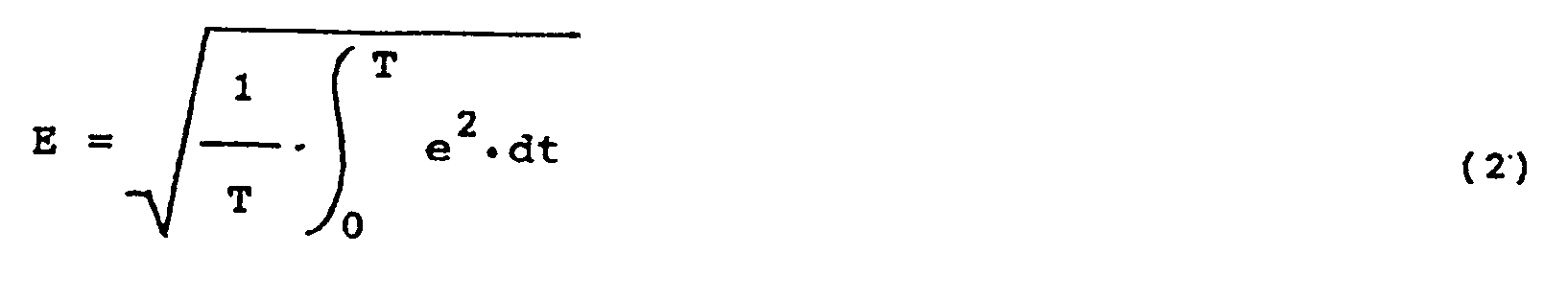
where R is the resistance of the load, and E is the effective voltage of the PWM signal. Figure 1 is a graph showing the waveform of the PWM signal. - When taking a cycle of the PWM signal as T and an instantaneous voltage as e, the effective voltage E becomes as follows:
- When dividing the instantaneous voltage e into sine wave (high harmonic) components en (n is a positive integer, i.e., n = 1, 2, 3 ...) by Fourier series conversion respectively, the maximum voltage E maxn of the sine wave components en becomes as follows:

where ω is an angle frequency of the PWM signal. - The effective voltage E becomes as follows.

- Then performing Fourier series conversion of the PWM signal as shown in figure 1, the following equation is obtained.

- Substituting ω = 2 π / T, the following equation is obtained.

- When obtaining the effective voltage E from above equation,

- In the above equation, only the DC component Eo (Eo = τV/T) of the PWM signal is essentially a voltage to be converted into an effective kinetic energy and other higher harmonic components become ineffective. As a result, the power conversion efficiency can be obtained by obtaining the ratio (Eo/E) of the DC component Eo and the effective voltage E. As will be clear from the equation described above, the effective voltage E is a function of τ/T, that is, the ratio (hereinafter called as duty ratio) of the ON time period or the pulse width τ of the PWM signal and the cycle T of the PWM signal. It is clear that the power conversion efficiency depends on the duty ratio.
- Figure 2 is a diagram showing the characteristic of the power conversion efficiency to the duty ratio when the PWM signal of the carrier frequency 44.1 kHz at the peak value of 1 V is applied to a load with the resistance R. In this case, it is assumed that the pulse width τ is varied while the cycle T of the PWM signal is made constant, thereby to change the duty ratio.
- In Figure 2, the solid line shows the actually measured value of the power conversion efficiency characteristic, while the broken line shows the value obtained from theoretical calculation made by dividing the value of the DC component Eo by the effective voltage e obtained from equation (7) for the higher harmonics from the first order (n=1) to the 100th order (n=100).
- As is clearly understood from the power conversion efficiency characteristics shown in Figure 2, it is theoretically and experimentally clarified that the power conversion efficiency is remarkably reduced as the duty ratio is decreased, that is, as the pulse width τ is shortened.
- This means that for the same effective voltage Ve can be obtained from two kinds of PWM signals PWMa and PWMb, the former PWMa having a larger peak value Va and the latter PWMb having a smaller peak value Vb while the former PWMa having a narrower pulse width τa and the latter having a wider pulse width τb as shown in Figure 3a and Figure 3b. However, the power conversion efficiency of the latter PWM signal PWMb shown in figure 3b is higher than that of the former PWM signal PWMa shown in figure 3a.
- Due to the above reason, it is advantageous that a PWM signal having the largest duty ratio in PWM signals with the same effective voltage is used to drive a load, e.g., the moving device like the disc rotation drive motor. However, PWM signals are required to have a fairly high effective voltage sufficient to make the moving device move at a high speed at a prescribed operation such as the start of the disc reproducing operation as described above. For this purpose, it is also necessary to set the peak value of a PWM signal as high as possible.
- PWM signals normally are applied to motors after being amplified through some amplifiers. The peak value of the PWM signal is therefore inevitably determined by the power supply voltage applied to the amplifier in the conventional disc reproducing apparatus. In this case, the PWM signal is obliged to have a relatively low duty ratio in the normal reproducing operation state which means that the moving device moves the optical discs with a relatively large power consumption.
- The present invention seeks to provide a control system for optical information reproducing apparatus which is able to drive a moving device of the reproducing apparatus with a relatively good power conversion efficiency from electrical energy to kinetic energy.
- According to the present invention there is provided a control system for an optical disc information reproducing apparatus in which information data stored in an optical disc is read out during a rotation of the optical disc by a light spot of a light beam, the system comprising:
- means for producing the light beam;
- means for relatively moving the optical disc and the light spot of the light beam;
- means responsive to the light beam reflected from the optical disc for reproducing the information data from the optical disc during the rotation of the optical disc, the reproducing means producing an electrical signal corresponding to the information data;
- means for deriving a servo control signal from the reproduced signal;
- means for modulating the servo control signal to a pulse width modulation (PWM) signal;
- means for amplifying the PWM signal; and
- means responsive to the output of the amplifying means for driving the moving means; characterised in that, the system further comprises,
- means for producing a response control signal upon detection of the need for, or on a command requiring, relative movement of the optical disc and light spot at faster or slower speeds than for normal data reproduction from the disc; and
- means for supplying the amplifying means with a power supply voltage which is changeable in response to the response control signal.
- For a better understanding of the present invention reference will now be made, by way of example, to the accompanying drawings, in which:
- Figure 1 is a graph showing the waveform of a PWM signal;
- Figure 2 is a graph showing the power conversion efficiency characteristics of a PWM signal relative to its duty ratio;
- Figures 3a and 3b are graphs showing waveforms of PWM signals for describing the problem of power conversion efficiency with regard to the duty ratio in known disc reproducing apparatus;
- Figure 4 is a block diagram showing a first embodiment of a control system for disc reproducing apparatus according to the present invention;
- Figure 5 shows a detail construction of an optical pickup of the embodiment of Figure 4;
- Figure 6 is a circuit diagram showing an example of a balanced transformerless (BTL) drive circuit of the embodiment of Figure 4;
- Figure 7 is a graph showing waveforms of the PWM signals for describing the operation of the embodiment of Figure 4;
- Figure 8 is a block diagram showing a second embodiment of a control system for disc reproducing apparatus according to the present invention;
- Figure 9 is a block diagram showing a third embodiment of a control system for disc reproducing apparatus according to the present invention;
- Figure 10 is a blocs diagram showing a fourth embodiment of a control system for disc reproducing apparatus according to the present invention;
- Figure 11 is a block diagram showing a fifth embodiment of a control system for disc reproducing apparatus according to the present invention;
- Figure 12 is a block diagram showing a sixth embodiment of a control system for disc reproducing apparatus according to the present invention;
- Figure 13 is a block diagram showing a seventh embodiment of a control system for disc reproducing apparatus according to the present invention;
- Figure 14 is a block diagram showing an eighth embodiment of a control system for disc reproducing apparatus according to the present invention;
- Figure 15 is a block diagram showing a ninth embodiment of a control system for disc reproducing apparatus according to the present invention; and
- Figure 16 is a block diagram showing a tenth embodiment of a control system for disc reproducing apparatus according to the present invention.
- The present invention will now be described in detail with reference to the accompanying drawings, namely, Figures 4 to 16. Throughout the drawings, like reference numerals and letters are used to designate elements like or equivalent to those used in Figures 1 to 3b (Prior Art) for simplicity of explanation.
- Referring now to Figure 4, a first embodiment of the present invention will be described in detail. Figure 4 shows a block diagram of a compact disc player. In Figure 1, the compact disc player is provided with a power supply circuit using a PWM technique. In the drawing, an
optical disc 11 is supported on aturntable 10. Theturntable 10 is coupled for rotation by adisc motor 12. Under theoptical disc 11 in the drawing, anoptical pickup 13 is mounted movably in the radial direction of theoptical disc 11. Theoptical pickup 13 is moved by a pickup transfer motor 14 (a linear motor) in the radial direction of theoptical disc 11. - Referring now to Figure 5, a symbolically represented
optical pickup device 13 is movably supported on afeeder 13a. Thefeeder 13a is driven by apickup transfer motor 14 as described later so thatoptical pickup device 13 moves radially with reference to the surface of theoptical disc 11. Theoptical pickup 13 comprises acarriage 13b, a source of a light beam, e.g., a semiconductor laser device 13c, acollimater lens 13d, a semi-transparent mirror 13e, a device for placing a laser beam LB on theoptical disc 11, e.g., anobjective lens 13f, a split photosensor 13g, a trackingactuator 13h and a focusingactuator 13i. The laser device 13c radiates the laser beam LB. Thecollimater lens 13d, the semi-transparent mirror 13e and theobjective lens 13f guides the laser beam LB to theoptical disc 11 so that the laser beam LB is placed on theoptical disc 11 in the form of light spot. Theoptical pickup 13 then scans concentric tracks of theoptical disc 11 one after another or a spiral track of theoptical disc 11 with the light spot of the laser beam LB, moving radially, in the direction of arrow A in the drawing, during the disc reproducing operation. The laser beam LB is reflected by theoptical disc 11 and then applied to the split photosensor 13g through theobjective lens 13f and the semi-transparent mirror 13e. The split photosensor 13g detects from the reflected laser beam LB information data responding to a state, e.g., a strength of the reflected laser beam LB and produces an electrical signal responding to the information. - The
objective lens 13f is movably mounted on thecarriage 13b of theoptical pickup 13. The trackingactuator 13h controls a position ofobjective lens 13f in the radial direction of theoptical disc 11 so that the light spot of the laser beam LB follows a center of a prescribed track in, e.g., the reproducing operation. The tracking control of theobjective lens 13f may be made by a tracking control system as follows, like a conventional one. The focusingactuator 13i controls the position ofobjective lens 13f in the perpendicular direction to the surface of theoptical disc 11 so that the laser beam LB is accurately focused with its light spot on a prescribed track in, e.g., the reproducing operation. The focusing control of theobjective lens 13f also may be made by a focusing control system as follows, like a conventional one. - Referring back to Figure 4, a reproduced signal is obtained from the
optical pickup 13 in the disc reproducing operation. The reproduced signal is applied to a tracking errorsignal producing circuit 15 and a tracking error signal TE corresponding to the tracking shift of theobjective lens 13f (see Figure 5) provided in theoptical pickup 13 is produced. This tracking error signal TE is applied to thetracking actuator 13h (see Figure 5) for moving theobjective lens 13f in theoptical pickup 13 in the radial direction of theoptical disc 11 through a drive circuit 16 to perform a tracking servo control. - The tracking error signal TE is applied to a low-
pass filter circuit 17, and after that high frequency components of the tracking error signal TE are removed. The tracking error signal TE is applied to a pulse width modulation (PWM)conversion circuit 19 through anadder 18. ThePWM conversion circuit 19 produces a pulse width modulation (PWM) signal by comparing the level of the tracking error signal TE outputted from the low-pass filter circuit 17 with a reference saw-tooth wave signal which is outputted from a saw-toothwave generation circuit 20. Therefore, the tracking error signal TE is converted to a pulse signal, i.e., the PWM signal which has a pulse width responding to the level of the tracking error signal TE. - The PWM signal for the normal disc reproducing operation is applied to a balanced transformerless (BTL) drive
circuit 21. TheBTL drive circuit 21 amnplifies the peak level of the PWM signal up to a power supply voltage applied from a selectablepower supply circuit 22 as described later. The amplified PWM signal is applied to the pickuptransfer drive motor 14. Thus, the pickuptransfer drive motor 14 controls the transfer speed of theoptical pickup 13. As a result, theoptical pickup 13 is transferred at a relatively low speed corresponding to the disc reproducing operation in the radial direction of theoptical disc 11. - Next, when a track jump for a relatively long distance is commanded to the
optical pickup 13 for, e.g., a long distance search operation, a long distance search operation command data corresponding to the distance and the direction for moving theoptical pickup 13 to a prescribed position on theoptical disc 11 at a high speed is generated from an operation control circuit such as amicrocomputer 23. The search operation command data is applied to a transfer compelling signal generation circuit 24. The transfer compelling signal generation circuit 24 generates a transfer compelling signal corresponding to the search operation command data. The transfer compelling signal is applied to thePWM conversion circuit 19 through theadder 18, thereby to produce a PWM signal which has a pulse width responding to the level of the transfer compelling signal. The PWM signal for the search operation has a pulse width responding to the level of the transfer compelling signal. The PWM signal is amplified through theBTL drive circuit 21 and then applied to the pickuptransfer drive motor 14. Thus, the pickuptransfer drive motor 14 controls the transfer speed of theoptical pickup 13. As a result, theoptical pickup 13 is transferred at a relatively high speed corresponding to the search operation in the radial direction of theoptical disc 11 to perform the track jump. - Further, the search operation command signal is applied to the selectable
power supply circuit 22. The selectablepower supply circuit 22 is comprised of a first and secondpower supply sources controllable selector switch 27. The firstpower supply source 25 produces a first power supply voltage V1. The secondpower supply source 26 produces a second power supply voltage V2 which is higher than the first power supply voltage V1. Thesepower supply sources fixed contact controllable selector switch 27. Acommon contact 27c of thecontrollable selector switch 27 is connected to the power supply input terminal of theBTL drive circuit 21. Thecommon contact 27c is selectively connected to the first and the secondfixed contact common contact 27c is connected to the firstfixed contact 27a through aselecter blade 27d. Accordingly, the first power supply voltage V1 is applied to theBTL drive circuit 21 together with the PWM signal converted from the tracking error signal TE. When the search operation command signal is applied to the selectablepower supply circuit 22, thecommon contact 27c is connected to the firstfixed contact 27a through theselecter blade 27d. Thus, the secondpower supply source 26 is selected to a connection to thecontrollable selector switch 27 to that the second power source voltage V2 is applied to theBTL drive circuit 21 together with the PWM signal converted from the transfer compelling signal for the search operation. - Therefore, in the track jump operation or the search operation, the second power supply voltage V2 is applied to the
BTL drive circuit 21. At that time, the peak level of the amplified PWM signal outputted from theBTL drive circuit 21 has a relatively high level, i.e., the second power supply voltage V2. Thereby the duty ratio of the amplified PWM signal for the search operation is held in an appropriate value. This allows the pickuptransfer drive motor 14 to be driven with an appropriate power conversion efficiency. Also, in a reproducing condition of theoptical disc 11, the first power supply voltage V1 is applied to theBTL drive circuit 21. At that time, the peak level of the amplified PWM signal outputted from theBTL drive circuit 21 is restrained in a relatively low level, i.e., the first power supply voltage V1. Thereby the duty ratio of the amplified PWM signal for the normal disc reproducing operation is increased.This allows the pickuptransfer drive motor 14 to be driven with high power conversion efficiency. The duty ratio of the PWM signal for the normal disc reproducing operation can be set to the duty ratio of the PWM signal for the search operation by adjusting the first and second power supply voltages V1 and V2 to each other. - Therefore, according to the embodiment as described above, the optical pickup control system for the compact disc player can drive the optical pickup at the high transfer speed with the higher effective voltage in the search operation. And also the system can drive the optical pickup at the low transfer speed with sufficient power conversion efficiency in the normal disc reproducing operation. As a result, the compact disc player can operate with relatively small power consumption.
- Figure 6 shows the detailed construction of the
BTL drive circuit 21 in Figure 4. The PWM signal outputted from thePWM conversion circuit 19 is applied to asignal input terminal 28. Thesignal input terminal 28 is directly connected to control input terminals of first andsecond switches 30 and 31. Further thesignal input terminal 28 is connected to control input terminals of third andfourth switches inverter 29. Thus, the PWM signals applied to the third andfourth switches second switches 30 and 31. The first and third switches 30 an 32 are connected in series between a power supplyvoltage input terminal 34 which is connected to the selectablepower supply circuit 22 and a ground terminal. The second andfourth switches 31 an 33 also are connected in series between the power supplyvoltage input terminal 34 and a ground terminal. Between a connection node of the first andthird switches 30 and 32 and another connection node of the second andfourth switches transfer drive motor 14 which is symbolized by a load having a resistance R in the drawing is connected. Then, the power supply voltage V1 or V2 on the powersupply input terminal 34 is applied to theload 14, i.e., the pickuptransfer drive motor 14 at the duty ratio corresponding to the PWM signal converted from the tracking error signal TE or the search operation command signal as described before. - Referring now to Figure 6 and 7, the operation of the
BTL drive circuit 21 will be described. Figure 7 shows waveform graphs of output signals obtained on theload 14. For example, when the power supply voltage V1 is applied to the powersupply input terminal 34, the PWM signal with the peak level V1 as shown by the solid line in Figure 7 is applied to the load resistance R. Also, when the power supply voltage V2 is applied to the powersupply input terminal 34, the PWM signal of the peak value V2 as shown by the broken line in Figure 7 is applied to theload 14. As will be clearly understood form Figure 7, even if the peak level of the PWM signal is changed between the voltages V1 and V2, the duty ratio of the PWM signals is left unchanged. Therefore, the dynamic range of theBTL drive circuit 21 can be enlarged and its gain can be increased. This results in the transfer control of theoptical pickup 13 becoming more effective both at the relatively low speed in the normal disc reproducing operation and at the relatively high speed in the search operation. - Referring now to Figure 8, a second embodiment of the present invention will described. The second embodiment shown in Figure 8 is also a compact disc player according to the present invention and is different from the first embodiment shown in Figure 4 as follws. Only the differences from the first embodiment will be described here for simplicity of explanation. In Figure 8, a reproduced signal outputted from the
optical pickup 13 is applied to adata slice circuit 34 and therein the signal has its waveform shaped to a rectangular pulse. The signal outputted from thedata slice circuit 34 is applied to a phase looked loop (PLL)circuit 35 and therein a synchronization signal is extracted from the reproduced signal. The synchronization signal outputted from thePLL circuit 35 is applied to a CLV servo controlsignal producing circuit 36 and therein an automatic frequency control (AFC) signal for a CLV rotation frequency servo control of the discrotation drive motor 12 and an automatic phase control (APC) signal for a CLV rotation phase servo control of the discrotation drive motor 12 are produced. The AFC and the APC signals produced from the CLV servo controlsignal producing circuit 36 is applied to thePWM conversion circuit 19. Further an abnormalAFC detection circuit 37 is connected between the CLV servo controlsignal producing circuit 36 and the selectablepower supply circuit 22. - Now the operation of the second embodiment as shown in Figure 8 will be described. During normal disc reproducing operation, the AFC signal outputted from the CLV servo control
signal producing circuit 36 has a relatively low value so that the discrotation drive motor 12 rotates with a relatively small power gain. At a start of the disc reproducing operation, thePLL circuit 35 fails to extract the synchronization signal. At that time, the AFC signal produced from the CLV servo controlsignal producing circuit 36 increases to an abnormal value larger than the value in the normal disc reproducing operation. The abnormalAFC detecting circuit 37 detects the abnormal AFC signal and then controls the selectablepower supply circuit 22. The selectablepower supply circuit 22 then applies the higher second power supply voltage V2 to theBTL drive circuit 21. As a result, the disc rotation drive control system of the second embodiment according to the present invention can bring thedisc rotation motor 12 in to the prescribed CLV rotation state with high power conversion efficiency. - Referring now to Figure 9, a third embodiment of the present invention will described. The third embodiment shown in Figure 9 is also a compact disc player according to the present invention and is different from the second embodiment shown in Figure 8 as follows. Only the differences from the second embodiment will be described here for simplicity of explanation. In Figure 9, an abnormal
synchronization detection circuit 38 is connected between thePLL circuit 35 and the selectablepower supply circuit 22. - Now the operation of the third embodiment as shown in Figure 9 will be described. During the normal disc reproducing operation, the synchronization signal outputted from the
PLL circuit 35 has a relatively low value so that the discrotation drive motor 12 rotates with a relatively small power gain. At a start of the disc reproducing operation, thePLL circuit 35 fails to extract the synchronization signal. At that time, the synchronization signal produced from thePLL circuit 35 increases to an abnormal value larger than the value for normal disc reproducing operation. The abnormalsynchronization detecting circuit 38 detects the abnormal synchronization signal and then controls the selectablepower supply circuit 22. The selectablepower supply circuit 22 then applies the higher second power supply voltage V2 to theBTL drive circuit 21. As a result, the disc rotation drive control system of the third embodiment according to the present invention can bring thedisc rotation motor 12 in to the prescribed CLV rotation state with high power conversion efficiency. - Referring now to Figure 10, a fourth embodiment of the present invention will described. The fourth embodiment shown in Figure 10 is also a compact disc player according to the present invention and is different from the first embodiment shown in Figure 4 as follows. Only the differences from the first embodiment will be described here for simplicity of explanation. In Figure 10, a
detector 39 responsive to a mechanical shock is provided and connected to the selectablepower supply circuit 22. - Now the operation of the fourth embodiment as shown in Figure 10 will be described. During the normal disc reproducing operation, the tracking error signal TE outputted from the tracking error signal
signal producing circuit 15 has a relatively low value. At that time, the trackingactuator 13h shifts theobjective lens 13f in the radial direction of theoptical disc 11 at relatively slow speed so that the light spot of the laser beam LB follows well the prescribed track. When the compact disc player, especially theoptical pickup 13 receives a mechanical shock, it may happen that the trackingactuator 13h fails to place the light spot on the prescribed track location. The light spot then can easily depart a relatively long distance from the drescribed track. At that time, thedetector 39 produces a detection signal in response to the mechanical shock. The detection signal is applied to the selectablepower supply circuit 22. The selectablepower supply circuit 22 then applies the higher second power supply voltage V2 to theBTL drive circuit 21. As a result, the PWM signal converted from, the tracking error signal TE is amplified to the level of the second power supply voltage V2. The trackingactuator 13h is then driven by a PWM signal which has a higher voltage than that in the normal tracking operation. As a result, the trackingactuator 13h can quickly shift the objective lens so that the light spot of the laser beam LB realigns on the prescribed track with high power conversion efficiency. - Referring now to Figure 11, a fifth embodiment of the present invention will described. The fifth embodiment shown in Figure 11 is also a compact disc player according to the present invention and is different from the fourth embodiment shown in Figure 10 as follows. Only the differences from the fourth embodiment will be described here for simplicity of explanation. In Figure 11, a focusing error
signal producing circuit 40 is provided in place of the tracking errorsignal producing circuit 15 in Figure 10. Further theBTL drive circuit 21 is connected to the focusingactuator 13i (see Figure 5). - Now the operation of the fifth embodiment as shown in Figure 11 will be described. During normal disc reproducing operation, a focusing error signal FE outputted from the focusing error signal
signal producing circuit 40 has a relatively low value so that the focusingactuator 13i shifts theobjective lens 13f in the longitudinal direction of the surface of theoptical disc 11 at relatively slow speed so that the light spot of the laser beam LB is well focused on the surface of theoptical disc 11. When the compact disc player, especially theoptical pickup 13 receives a mechanical shock, it may happen that the focusingactuator 13i fails to focus the light spot on the surface of theoptical track 11. The light spot can then easily be focused a relatively long distance from the surface of theoptical track 11. At that time, thedetector 39 produces a detection signal in response to the mechanical shock. The detection signal is applied to the selectablepower supply circuit 22. The selectablepower supply circuit 22 then applies the higher second power supply voltage V2 to theBTL drive circuit 21. As a result, the PWM signal converted from the focusing error signal FE is amplified to the level of the second power supply voltage V2. The focusingactuator 13i is then driven by the PWM signal which has a higher voltage than that in the normal focusing operation. As a result, the focusingactuator 13i can quickly shift the objective lens so that the light spot of the laser beam LB is focused on the surface of theoptical disc 11 with high power conversion efficiency. - Referring now to Figure 12, a sixth embodiment of the present invention will described. The sixth embodiment shown in Figure 12 is also a compact disc player according to the present invention and is different from the second embodiment shown in Figure 8 as follows. Only the differences from the second embodiment will be described here for simplicity of explanation. In Figure 12, the
microcomputer 23 is connected to the CLV servo controlsignal producing circuit 36 as well as the selectablepower supply circuit 22. - Now the operation of the sixth embodiment as shown in Figure 12 will be described. During normal disc reproducing operation, the synchronization signal outputted from the
PLL circuit 35 has a relatively low value so that the discrotation drive motor 12 rotates with a relatively small power gain. When a reproducing stop operation is commanded, themicrocomputer 23 produces a a stop operation command signal of a high (H) level signal. The stop operation command signal is applied to both the CLV servo controlsignal producing circuit 36 and the selectablepower supply circuit 22. The CLV servo controlsignal producing circuit 36 produces a signal which operates to damp the rotation of thedisc drive motor 12. The damping signal is converted to a PWM signal in thePWM conversion circuit 19. Also, the selectablepower supply circuit 22 applies the second power supply voltage V2 to theBTL drive circuit 21. Therefore, the PWM signal converted from the damping signal is amplified at its peak level to the second power supply voltage V2 in theBTL drive circuit 21. The amplified PWM signal converted from the damping signal is appled to the discrotation drive motor 12 so that the discrotation drive motor 12 has its rotation damped quickly. As a result, the disc reproducing stop control system of the sixth embodiment according to the present invention can bring the discrotation drive motor 12 or theturntable 10 into stop condition quickly and with high power conversion efficiency. - Referring now to Figure 13, a seventh embodiment of the present invention will described. The seventh embodiment shown in Figure 13 is also a compact disc player according to the present invention and is different from the first embodiment shown in Figure 4 as follows. Only the differences from the first embodiment will be described here for simplicity of explanation. In Figure 13, the
BTL circuit 21 is connected to thetracking actuator 13h of theoptical pickup 13. Also, themicrocomputer 23 is connected to the selectablepower supply circuit 22. - Now the operation of the seventh embodiment as shown in Figure 13 will be described. During normal disc reproducing operation, the tracking error signal TE outputted from the tracking error
signal producing circuit 15 has a relatively low value. At that time, the trackingactuator 13h shifts theobjective lens 13f in the radial direction of theoptical disc 11 at relatively slow speed so that the light spot of the laser beam LB follows well the prescribed track. When a track jump for a relatively short distance is commanded of the trackingactuator 13h for, e.g., a short distance search operation, a short distance search operation command signal corresponding to the distance and the direction for moving the trackingactuator 13h to a prescribed position on theoptical disc 11 at a high speed is generated from themicrocomputer 23. The short distance search operation command signal is applied to the selectablepower supply circuit 22 the selectablepower supply circuit 22 thus applies the second power supply voltage V2 to theBTL drive circuit 21 so that the PWM signal converted from the tracking error signal TE is amplified to the second power supply voltage V2. Thus, the trackingactuator 13h kicks theobjective lens 13f in the radial direction of theoptical disc 11 at a relatively fast speed. As a result, tieobjective lens 13f is shifted at the relatively fast speed corresponding to the short distance search operation in the radial direction of theoptical disc 11 to perform the short distance track jump. - Referring now to Figure 14, an eighth embodiment of the present invention will be described. The eighth embodiment shown in Figure 14 is also a compact disc player according to the present invention and is different from the seventh embodiment shown in Figure 13 as follows. Only the differences from the seventh embodiment will be described here for simplicity of explanation. In Figure 14, a focusing error
signal producing circuit 40 is provided in place of the tracking errorsignal producing circuit 15 in Figure 13. Further theBTL drive circuit 21 is connected to the focusingactuator 13i (see Figure 5). - Now the operation of the eighth embodiment as shown in Figure 14 will be described. In the reproducing stop condition, the
objective lens 13f is settled at a prescribed position. When a reproducing operation is commanded, the focusingactuator 13i shifts theobjective lens 13f in the perpendicular direction to the surface of theoptical disc 11 toward a the proper position so that the light spot of the laser beam LB is well focused on the surface of theoptical disc 11. Until the proper focus is obtained, the focusing errorsignal producing circuit 40 produces a focusing error signal FE of a relatively high level. The high level focusing error signal FE is converted to a PWM signal in thePWM conversion circuit 19 and applied to theBTL drive circuit 21. Also, themicrocomputer 23 produces a reproducing operation command signal of a high level. The reproducing operation command signal is applied to the selectablepower supply circuit 22. The selectablepower supply circuit 22 thus applies the second power supply voltage V2 to theBTL drive circuit 21 so that the PWM signal converted from the focusing error signal FE is amplified to the second power supply voltage V2. Thus, the focusingactuator 13i kicks theobjective lens 13f in the perpendicular direction to the surface of theoptical disc 11 at a relatively fast speed. As a result, theobjective lens 13f is shifted quickly and with high power conversion efficiency to the proper position so that the light spot of the laser beam LB is well focused on the surface of theoptical disc 11. - Referring now to Figure 15, a ninth embodiment of the present invention will described. The ninth embodiment shown in Figure 15 is also a compact disc player according to the present invention and is different from the fourth embodiment shown in Figure 10 as follows. Only the differences from the fourth embodiment will be described here for simplicity of explanation. In Figure 15, a
detector 41 is connected to theoptical pickup 13 to receive the reproduced signal. Thedetector 41 is further connected to the trackingerror producing circuit 15 to receive the tracking error signal TE. Thedetector 41 output terminal is connected to the selectablepower supply circuit 22. The selectablepower supply circuit 22 has a third power supply source 42 in place of the secondpower supply source 26 but retains the firstpower supply source 25. The third power supply source 42 produces a third power supply voltage V3 which is lower than the first power supply voltage V1. - Now the operation of the ninth embodiment as shown in Figure 15 will be described. During normal disc reproducing operation, the
optical pickup 13 produces the reproduced signal corresponding to the recorded information of theoptical disc 11 and, the tracking error signalsignal producing circuit 15 produces a tracking error signal TE of a relatively low level. In the above condition, the selectablepower supply circuit 22 applies the first power supply voltage V1 to theBTL drive circuit 21. When theoptical pickup 13 traces an inferior portion of theoptical disc 11 such as a portion damaged by dust or a flaw, theoptical pickup 13 fails to produce a reproduced signal or produces a reproduced signal of a very high level. At that time, the tracking errorsignal producing circuit 15 produces a tracking error signal TE of a relatively high level. Then, thedetector 41 produces a high level signal in response to both the high level tracking error signal TE and the lack of a reproduced signal or a reproduced signal of an excessive level. The high level signal is applied to the selectablepower supply circuit 22. The selectablepower supply circuit 22 then applies the third power supply voltage V3 to theBTL drive circuit 21. As a result, the PWM signal converted from the tracking error signal TE is amplified with its peak level at the level of the third power supply voltage V3. The trackingactuator 13h is then driven by a PWM signal which has a lower voltage than that in a normal tracking operation. The trackingactuator 13h is thus decreased in its driving power gain. As a result, theobjective lens 13f is effectively held in the position that the trackingactuator 13h placed the light spot of the laser beam LB on the prescribed track before tracking the inferior portion. Thus, the tracking actuator control according to the embodiment can operate with a high power conversion efficiency in a normal reproducing operation as well as at the tracking of an inferior portion of theoptical disc 11. - Referring now to Figure 16, a tenth embodiment of the present invention will described. The tenth embodiment shown in Figure 16 is also a compact disc player according to the present invention and is different from the ninth embodiment shown in Figure 15 as follows. Only the differences from the ninth embodiment will be described here for simplicity of explanation. In Figure 16, a focusing error
signal producing circuit 40 is provided in place of the tracking errorsignal producing circuit 15 in Figure 15. Further theBTL drive circuit 21 is connected to the focusingactuator 13i (see Figure 5). - Now the operation of the tenth embodiment as shown in Figure 16 will be described. During normal disc reproducing operation, the
optical pickup 13 produces a reproduced signal corresponding to the recorded information on theoptical disc 11 and, the focusing errorsignal producing circuit 40 produces a focusing error signal FE of a relatively low level. In the above condition, the selectablepower supply circuit 22 applies the first power supply voltaye V1 to theBTL drive circuit 21. When theoptical pickup 13 tracks an inferior portion of theoptical disc 11, theoptical pickup 13 fails to produce the reproduced signal or produces a reproduced signal of a very high level. At that time, the focusing errorsignal producing circuit 15 produces a focusing error signal FE of a relatively high level. Then, thedetector 41 produces a high level signal in response to both the high level focusing error signal FE and the lack of the reproduced signal or the reproduced signal of an excessive level. The high level signal is applied to the selectablepower supply circuit 22. The selectablepower supply circuit 22 then applies the third power supply voltage V3 to theBTL drive circuit 21. As a result, the PWM signal converted from the focusing error signal FE is amplified with its peak level at the level of the third grower supply voltage V3. The focusing actuator 131 is then driven by the PWM signal which has a lower voltage than that in the normal focusing operation. The focusing actuator 131 is then decreased in its driving power gain. As a result, theobjective lens 13f is held effectively in the position that the focusing actuator 131 focused the light spot of the laser beam LB to the surface of theoptical disc 11 before tracking the inferior portion. Thus, the focusing actuator control according to this embodiment can operate with high power conversion efficiency in a normal reproducing operation as well as when tracking an inferior portion of theoptical disc 11.
Claims (26)
means (13c) for producing the light beam (LB);
means (10, 13, 13f) for relatively moving the optical disc (11) and the light spot of the light beam (LB);
means (13, 13g) responsive to the light beam (LB) reflected from the optical disc (11) for reproducing the information data from the optical disc (11) during the rotation of the optical disc (11), the reproducing means (13, 13g) producing an electrical signal corresponding to the information data;
means (15, 34, 40) for deriving a servo control signal from the reproduced signal;
means (19, 20) for modulating the servo control signal to a pulse width modulation (PWM) signal;
means (21) for amplifying the PWM signal; and
means (12, 14, 13h, 13i) responsive to the output of the amplifying means (21) for driving the moving means (10, 13, 13f); characterised in that, the system further comprises,
means (23, 37, 38, 39, 41) for producing a response control signal upon detection of the need for, or on a command requiring, relative movement of the optical disc (11) and light spot at faster or slower speeds than for normal data reproduction from the disc; and
means (22) for supplying the amplifying means (21) with a power supply voltage which is changeable in response to the response control signal.
Applications Claiming Priority (20)
| Application Number | Priority Date | Filing Date | Title |
|---|---|---|---|
| JP29131585A JPS62149043A (en) | 1985-12-24 | 1985-12-24 | Tracking controller |
| JP291315/85 | 1985-12-24 | ||
| JP29131685A JPS62150531A (en) | 1985-12-24 | 1985-12-24 | Focus controller |
| JP29131285A JPS62149077A (en) | 1985-12-24 | 1985-12-24 | Control device for pickup carrying motor |
| JP291318/85 | 1985-12-24 | ||
| JP29131485A JPS62149069A (en) | 1985-12-24 | 1985-12-24 | Disk motor controlling device |
| JP291316/85 | 1985-12-24 | ||
| JP29132085A JPS62150530A (en) | 1985-12-24 | 1985-12-24 | Focus controller |
| JP29131385A JPS62149068A (en) | 1985-12-24 | 1985-12-24 | Disk motor controlling device |
| JP291317/85 | 1985-12-24 | ||
| JP29131985A JPS62150532A (en) | 1985-12-24 | 1985-12-24 | Focus controller |
| JP291313/85 | 1985-12-24 | ||
| JP291312/85 | 1985-12-24 | ||
| JP291319/85 | 1985-12-24 | ||
| JP291320/85 | 1985-12-24 | ||
| JP29131785A JPS62150554A (en) | 1985-12-24 | 1985-12-24 | Disc motor controller |
| JP29132185A JPS62150534A (en) | 1985-12-24 | 1985-12-24 | Tracking controller |
| JP29131885A JPS62150573A (en) | 1985-12-24 | 1985-12-24 | Tracking controller |
| JP291314/85 | 1985-12-24 | ||
| JP291321/85 | 1985-12-24 |
Publications (2)
| Publication Number | Publication Date |
|---|---|
| EP0237682A1 EP0237682A1 (en) | 1987-09-23 |
| EP0237682B1 true EP0237682B1 (en) | 1991-02-27 |
Family
ID=27580492
Family Applications (1)
| Application Number | Title | Priority Date | Filing Date |
|---|---|---|---|
| EP86310026A Expired - Lifetime EP0237682B1 (en) | 1985-12-24 | 1986-12-22 | Control system for optical information reproducing apparatus |
Country Status (4)
| Country | Link |
|---|---|
| US (1) | US4783774A (en) |
| EP (1) | EP0237682B1 (en) |
| KR (1) | KR910001277B1 (en) |
| DE (1) | DE3677764D1 (en) |
Families Citing this family (27)
| Publication number | Priority date | Publication date | Assignee | Title |
|---|---|---|---|---|
| JP2630375B2 (en) * | 1986-02-28 | 1997-07-16 | パイオニア株式会社 | Information reproducing device having address search function |
| JP2565265B2 (en) * | 1987-11-28 | 1996-12-18 | ソニー株式会社 | Optical information processing device |
| JPH0281332A (en) * | 1988-09-19 | 1990-03-22 | Hitachi Ltd | Ultra-small light memory |
| JPH02162529A (en) * | 1988-12-15 | 1990-06-22 | Pioneer Electron Corp | Optical recorder and optical disk |
| FI896219A0 (en) * | 1989-04-28 | 1989-12-22 | Antti Aarne Ilmari Lange | ANALYZING AND FOUNDATION CALIBRATION AV DETEKTORSYSTEM. |
| DE3926272A1 (en) * | 1989-08-09 | 1991-02-14 | Thomson Brandt Gmbh | CIRCUIT ARRANGEMENT FOR AUTOMATIC GAIN CONTROL |
| JPH0378490A (en) * | 1989-08-18 | 1991-04-03 | Fujitsu Ltd | Pwm controlling type of spindle motor |
| DE69124406T2 (en) * | 1990-03-31 | 1997-08-28 | Sanyo Electric Co | Motor control circuit for disc player |
| JPH0594628A (en) * | 1991-04-30 | 1993-04-16 | Fuji Xerox Co Ltd | Optical recording and reproducing device |
| JPH05342508A (en) * | 1992-02-19 | 1993-12-24 | Canon Inc | Magnetic head driving device, and magnetic recording device and information recording method |
| JPH05325403A (en) * | 1992-05-22 | 1993-12-10 | Sony Corp | Spindle servo circuit |
| JP2795365B2 (en) * | 1992-05-28 | 1998-09-10 | インターナショナル・ビジネス・マシーンズ・コーポレイション | Digital closed loop system control method and system, and disk storage device using the system |
| US5289097A (en) * | 1992-08-18 | 1994-02-22 | International Business Machines Corporation | Spindle control method and apparatus for disk drive |
| JPH087467A (en) * | 1994-06-14 | 1996-01-12 | Teac Corp | Optical disk device |
| JP3406133B2 (en) * | 1995-10-23 | 2003-05-12 | 富士通株式会社 | Optical storage device |
| US5808978A (en) * | 1995-10-27 | 1998-09-15 | Acer Peripherals Inc. | Speed control of optical information reproduction apparatus |
| TW440817B (en) * | 1999-05-20 | 2001-06-16 | Asustek Comp Inc | Method for controlling the rotating speed of compact disk player and device thereof |
| TW460870B (en) | 1999-11-26 | 2001-10-21 | Asustek Comp Inc | Focusing speed control method of optical pickup head |
| WO2004059649A1 (en) | 2002-12-30 | 2004-07-15 | Koninklijke Philips Electronics N.V. | Method for driving an actuator, actuator drive, and apparatus comprising an actuator |
| US20060072417A1 (en) * | 2004-09-03 | 2006-04-06 | Chao-Hsin Tseng | Device for reducing power consumption of optical drive and method for the same |
| KR100728365B1 (en) * | 2004-12-07 | 2007-06-14 | 엘지전자 주식회사 | Noise Attenuation System using Drive channel consisting of BTL operating circuit |
| US7535806B2 (en) * | 2005-07-07 | 2009-05-19 | Cinram International Inc. | Apparatus and method for detecting laser dropout |
| US7567054B2 (en) * | 2006-03-01 | 2009-07-28 | Media Tek Inc. | Control circuit and method of controlling rotation frequency of spindle in optical disc drive for reducing frequency difference of output signals respectively corresponding to different disc rotation modes |
| KR101176179B1 (en) * | 2007-03-14 | 2012-08-22 | 삼성전자주식회사 | Apparatus and method for controlling a voltage converting mode |
| US8604709B2 (en) | 2007-07-31 | 2013-12-10 | Lsi Industries, Inc. | Methods and systems for controlling electrical power to DC loads |
| US7598683B1 (en) | 2007-07-31 | 2009-10-06 | Lsi Industries, Inc. | Control of light intensity using pulses of a fixed duration and frequency |
| US8903577B2 (en) | 2009-10-30 | 2014-12-02 | Lsi Industries, Inc. | Traction system for electrically powered vehicles |
Family Cites Families (9)
| Publication number | Priority date | Publication date | Assignee | Title |
|---|---|---|---|---|
| JPS56134359A (en) * | 1980-03-22 | 1981-10-21 | Victor Co Of Japan Ltd | Driving circuit of feeder direct current motor |
| JPS5753877A (en) * | 1980-09-12 | 1982-03-31 | Victor Co Of Japan Ltd | Pickup mechanism driver for reproducer of rotary information recording medium |
| WO1983003325A1 (en) * | 1982-03-18 | 1983-09-29 | Sumi, Yasuaki | Speed control circuit for motor |
| EP0098076A1 (en) * | 1982-06-14 | 1984-01-11 | Nec Corporation | Beam access apparatus for optical disc system |
| JPS59146448A (en) * | 1983-02-10 | 1984-08-22 | Sony Corp | Optical disk player |
| US4654515A (en) * | 1983-05-28 | 1987-03-31 | Kabushiki Kaisha Toshiba | Optical head for focussing a light beam on an information recording medium |
| JPS60173767A (en) * | 1984-02-20 | 1985-09-07 | Sony Corp | Speed control circuit of optical disc |
| US4684797A (en) * | 1984-02-29 | 1987-08-04 | Kabushiki Kaisha Toshiba | Optical system and method for reducing vibration of an objective lens in an optical head assembly of an optical read/write system |
| JPS60241784A (en) * | 1984-05-15 | 1985-11-30 | Sanyo Electric Co Ltd | Controller of dc servo motor |
-
1986
- 1986-12-22 DE DE8686310026T patent/DE3677764D1/en not_active Expired - Lifetime
- 1986-12-22 EP EP86310026A patent/EP0237682B1/en not_active Expired - Lifetime
- 1986-12-23 US US07/001,332 patent/US4783774A/en not_active Expired - Fee Related
- 1986-12-24 KR KR1019860011166A patent/KR910001277B1/en not_active IP Right Cessation
Also Published As
| Publication number | Publication date |
|---|---|
| DE3677764D1 (en) | 1991-04-04 |
| KR870006557A (en) | 1987-07-13 |
| KR910001277B1 (en) | 1991-02-26 |
| US4783774A (en) | 1988-11-08 |
| EP0237682A1 (en) | 1987-09-23 |
Similar Documents
| Publication | Publication Date | Title |
|---|---|---|
| EP0237682B1 (en) | Control system for optical information reproducing apparatus | |
| JPH05775B2 (en) | ||
| CN1180889A (en) | Optical heat transfer circuit, optical head and reproducing apparatus introducing the same circuit | |
| US4656617A (en) | Start-control method and circuit for optical disc play-back system | |
| US6791915B1 (en) | Optical disc track access apparatus and method for optical disc reproducer | |
| JPH01223640A (en) | Optical recording and reproducing device | |
| KR100486271B1 (en) | Apparatus and method for generating tracking error signal | |
| JP2705207B2 (en) | Off-track detector | |
| KR0127523B1 (en) | Tracking servo apparatus | |
| JPS62150573A (en) | Tracking controller | |
| JPH0750529B2 (en) | Optical disc playback device | |
| KR950007295B1 (en) | Focus oa signal transmitting circuit of disk reproduction system | |
| JPS62150531A (en) | Focus controller | |
| JPS62150532A (en) | Focus controller | |
| KR100628184B1 (en) | Apparatus for controlling actuator of optical record/player | |
| KR910005648B1 (en) | Focus servo circuit and method thereof for optical disk reproducing apparatus | |
| JPS62149043A (en) | Tracking controller | |
| KR20010092257A (en) | Disk device | |
| JPS62150534A (en) | Tracking controller | |
| JPS62149069A (en) | Disk motor controlling device | |
| JPS629535A (en) | Focus control circuit for optical disc reproducing device | |
| KR100238285B1 (en) | Tracking servo circuit for optical pickup | |
| JPH1021566A (en) | Tracking servo device | |
| JPH0782650B2 (en) | Drive voltage generation circuit | |
| JP3775805B2 (en) | Information truck search device |
Legal Events
| Date | Code | Title | Description |
|---|---|---|---|
| PUAI | Public reference made under article 153(3) epc to a published international application that has entered the european phase |
Free format text: ORIGINAL CODE: 0009012 |
|
| 17P | Request for examination filed |
Effective date: 19870112 |
|
| AK | Designated contracting states |
Kind code of ref document: A1 Designated state(s): DE GB |
|
| 17Q | First examination report despatched |
Effective date: 19890911 |
|
| GRAA | (expected) grant |
Free format text: ORIGINAL CODE: 0009210 |
|
| AK | Designated contracting states |
Kind code of ref document: B1 Designated state(s): DE GB |
|
| REF | Corresponds to: |
Ref document number: 3677764 Country of ref document: DE Date of ref document: 19910404 |
|
| PLBE | No opposition filed within time limit |
Free format text: ORIGINAL CODE: 0009261 |
|
| STAA | Information on the status of an ep patent application or granted ep patent |
Free format text: STATUS: NO OPPOSITION FILED WITHIN TIME LIMIT |
|
| 26N | No opposition filed | ||
| PGFP | Annual fee paid to national office [announced via postgrant information from national office to epo] |
Ref country code: GB Payment date: 19941213 Year of fee payment: 9 |
|
| PGFP | Annual fee paid to national office [announced via postgrant information from national office to epo] |
Ref country code: DE Payment date: 19941222 Year of fee payment: 9 |
|
| PG25 | Lapsed in a contracting state [announced via postgrant information from national office to epo] |
Ref country code: GB Effective date: 19951222 |
|
| GBPC | Gb: european patent ceased through non-payment of renewal fee |
Effective date: 19951222 |
|
| PG25 | Lapsed in a contracting state [announced via postgrant information from national office to epo] |
Ref country code: DE Effective date: 19960903 |