EP0236784A2 - Filter for the separation of solids from liquids - Google Patents
Filter for the separation of solids from liquids Download PDFInfo
- Publication number
- EP0236784A2 EP0236784A2 EP87102098A EP87102098A EP0236784A2 EP 0236784 A2 EP0236784 A2 EP 0236784A2 EP 87102098 A EP87102098 A EP 87102098A EP 87102098 A EP87102098 A EP 87102098A EP 0236784 A2 EP0236784 A2 EP 0236784A2
- Authority
- EP
- European Patent Office
- Prior art keywords
- pressure
- line
- filter
- agitator
- linear motor
- Prior art date
- Legal status (The legal status is an assumption and is not a legal conclusion. Google has not performed a legal analysis and makes no representation as to the accuracy of the status listed.)
- Granted
Links
- 239000007787 solid Substances 0.000 title claims description 9
- 239000007788 liquid Substances 0.000 title claims description 5
- 238000000926 separation method Methods 0.000 title 1
- 239000012065 filter cake Substances 0.000 claims abstract description 35
- 230000001105 regulatory effect Effects 0.000 claims description 3
- 238000001914 filtration Methods 0.000 abstract description 2
- 238000009499 grossing Methods 0.000 description 7
- 238000003756 stirring Methods 0.000 description 5
- 238000003825 pressing Methods 0.000 description 4
- 239000000706 filtrate Substances 0.000 description 3
- IJGRMHOSHXDMSA-UHFFFAOYSA-N Atomic nitrogen Chemical compound N#N IJGRMHOSHXDMSA-UHFFFAOYSA-N 0.000 description 2
- 238000010586 diagram Methods 0.000 description 2
- 230000035699 permeability Effects 0.000 description 2
- 239000000725 suspension Substances 0.000 description 2
- 238000005406 washing Methods 0.000 description 2
- 230000000712 assembly Effects 0.000 description 1
- 238000000429 assembly Methods 0.000 description 1
- 238000001035 drying Methods 0.000 description 1
- 230000000694 effects Effects 0.000 description 1
- 239000004744 fabric Substances 0.000 description 1
- 239000007789 gas Substances 0.000 description 1
- 239000011521 glass Substances 0.000 description 1
- 238000000034 method Methods 0.000 description 1
- 229910052757 nitrogen Inorganic materials 0.000 description 1
- 239000000047 product Substances 0.000 description 1
- 238000011144 upstream manufacturing Methods 0.000 description 1
- 238000004018 waxing Methods 0.000 description 1
Images

Classifications
-
- B—PERFORMING OPERATIONS; TRANSPORTING
- B01—PHYSICAL OR CHEMICAL PROCESSES OR APPARATUS IN GENERAL
- B01D—SEPARATION
- B01D29/00—Filters with filtering elements stationary during filtration, e.g. pressure or suction filters, not covered by groups B01D24/00 - B01D27/00; Filtering elements therefor
- B01D29/01—Filters with filtering elements stationary during filtration, e.g. pressure or suction filters, not covered by groups B01D24/00 - B01D27/00; Filtering elements therefor with flat filtering elements
- B01D29/075—Filters with filtering elements stationary during filtration, e.g. pressure or suction filters, not covered by groups B01D24/00 - B01D27/00; Filtering elements therefor with flat filtering elements located in a closed housing and comprising scrapers or agitators on the cake side of the filtering elements, e.g. Nutsche- or Rosenmund-type filters for performing multiple step operations such as chemical reactions, filtering and cake treatment
-
- B—PERFORMING OPERATIONS; TRANSPORTING
- B01—PHYSICAL OR CHEMICAL PROCESSES OR APPARATUS IN GENERAL
- B01D—SEPARATION
- B01D29/00—Filters with filtering elements stationary during filtration, e.g. pressure or suction filters, not covered by groups B01D24/00 - B01D27/00; Filtering elements therefor
- B01D29/60—Filters with filtering elements stationary during filtration, e.g. pressure or suction filters, not covered by groups B01D24/00 - B01D27/00; Filtering elements therefor integrally combined with devices for controlling the filtration
- B01D29/606—Filters with filtering elements stationary during filtration, e.g. pressure or suction filters, not covered by groups B01D24/00 - B01D27/00; Filtering elements therefor integrally combined with devices for controlling the filtration by pressure measuring
-
- B—PERFORMING OPERATIONS; TRANSPORTING
- B01—PHYSICAL OR CHEMICAL PROCESSES OR APPARATUS IN GENERAL
- B01D—SEPARATION
- B01D29/00—Filters with filtering elements stationary during filtration, e.g. pressure or suction filters, not covered by groups B01D24/00 - B01D27/00; Filtering elements therefor
- B01D29/62—Regenerating the filter material in the filter
- B01D29/64—Regenerating the filter material in the filter by scrapers, brushes, nozzles, or the like, acting on the cake side of the filtering element
- B01D29/6469—Regenerating the filter material in the filter by scrapers, brushes, nozzles, or the like, acting on the cake side of the filtering element scrapers
- B01D29/6476—Regenerating the filter material in the filter by scrapers, brushes, nozzles, or the like, acting on the cake side of the filtering element scrapers with a rotary movement with respect to the filtering element
-
- B—PERFORMING OPERATIONS; TRANSPORTING
- B01—PHYSICAL OR CHEMICAL PROCESSES OR APPARATUS IN GENERAL
- B01D—SEPARATION
- B01D29/00—Filters with filtering elements stationary during filtration, e.g. pressure or suction filters, not covered by groups B01D24/00 - B01D27/00; Filtering elements therefor
- B01D29/76—Handling the filter cake in the filter for purposes other than for regenerating
Definitions
- the invention relates to a filter for separating solids from liquids and for treating the filter cake formed with the solids on the filter surface, in the housing of which an agitator is installed, which has a motor for the rotary movement and at least one linear motor in the form of a hydraulic cylinder is equipped, in the latter of which the piston can be acted upon by the pressure medium of a pressure source for the upward and downward movement.
- the agitator consists essentially of a rotatable as well as a raised and lowered drive shaft, at the end of which two or more agitator arms are attached. Depending on the direction of rotation and / or the lifting or snaking movement, additional operations can be carried out.
- An essential operation that the agitator is supposed to perform is to smooth the surface of the filter base forming filter cake. It cannot be avoided that the filter cake does not build up evenly during the filter operation, but that cracks can form.
- the agitator has the task of smoothing out the filter cake so that the cracks in the filter cake close. This ensures uniform permeability of the filter cake.
- This object is achieved according to the invention in that for the downward movement of the agitator, one piston side of the linear motor is acted upon via a first line by a constant pressure of the pressure medium regulated by a pressure control valve, while for the adjustment of the pressure on the other piston side of the linear motor, this Side is connected to a second line having a pressure holding valve.
- the invention is described below using the example of a Nutsche filter for printing operation of a known type, as is shown schematically in FIG. 1.
- the application of the invention is not limited to pressure filters, but can also be used with open filters and those with vacuum operation.
- the Nutsche filter designated overall by 1 in FIG. 1, has a housing 2, which is generally cylindrical in shape and through a horizontally arranged bottom 3 is completed; this can either be detachably or non-releasably connected to the housing 2.
- a closure 4 is provided in the housing wall, through which the filter cake forming in the interior of the housing 2 can be removed.
- the turbidity or suspension to be filtered can, for example, be introduced into the interior of the housing through a line connection 6 provided on the cover part of the housing 2.
- a connection (not shown) for the introduction of a pressure medium, for example nitrogen or the like, can be provided.
- a filter surface is arranged on the bottom 3 of the housing 2 and is covered with a filter medium, for example a filter cloth, a sieve or a solid, porous plate.
- a filter medium for example a filter cloth, a sieve or a solid, porous plate.
- a lifting device is constructed on the cover part of the housing 2, which consists of two linear motors 10, e.g. Hydraulic cylinder, composed.
- the linear motors 10 are connected to one another by means of a connecting platform 11 and are fastened on bases 12 which are supported on the cover part of the housing 2.
- the connection platform 11 is guided by guide columns 56.
- a stirrer 18 is fastened, which has two stirrer arms 19, for example.
- linear motor 10 instead of the two linear motors 10, only one can be used only linear motor 10 in the form of a hydraulic cylinder 8 can be used, see FIG. 2.
- the motor 14 is connected to the piston rod of the linear motor 10 by means of a cantilevered support arm 20 for generating the rotary movement of the agitator mechanism 13.
- a filter drain 21 designed as a cavity, from which the filtrate can be discharged through a drain connector 22 arranged in the center.
- the bottom 3 is delimited on the outer circumference by an annular wall 24 and is supported by webs 26 made of a double-T profile.
- the agitator 13 has different functions depending on the product to be processed, of which the treatment of the filter cake is of particular importance.
- the filter cake that forms on the filter medium shrinks when the filtrate is removed. This creates cracks in the entire filter cake, which can extend to the filter medium. In the pressure mode of a Nutsche filter, the gas introduced for pressurization can escape through these cracks without having the desired effect. In addition, the cracks mean that the filter cake is not evenly flowed through by the washing liquid or compressed air during washing and drying.
- One of the functions of the agitator 13 is to smooth the filter cake so that the cracks close and thereby achieve a uniform permeability of the filter cake.
- the filter cake is additionally pressed out by the pressure exerted by the agitator 13.
- the stirring arms 19 are expediently designed like runners.
- the hydraulic control described in FIG. 2 is provided, with which the linear motor 10 designed as hydraulic cylinder 8 is applied, the piston rod 9 of which supports the platform 11 or the support arm that carries the agitator 13 20 supports.
- the hydraulic cylinder 8 is connected to a first line 31 on its piston rod-side piston side and to a second line 31 on the other, piston rod-free side.
- a pressure control valve 32 is connected to line 31, with which a constant pressure in line 31 can be set and measured with a pressure meter 33.
- a pressure maintaining valve 34 is connected in line 31, which keeps the pressure upstream of this valve constant irrespective of the amount flowing through.
- a check valve 35 is arranged parallel to the pressure holding valve 34, which opens when the agitator 13 is raised, but is closed in smooth pond operation.
- a constant pressure can be exerted with the agitator 13 in that a constant pressure is set on the two piston sides or in the lines 30, 31, so that there is a constant pressure drop between the lines 30, 31 .
- the pressing force exerted by the stirring arms 19 when the filter cake is smoothed is composed of the agitator weight and the force exerted by the pressure in the line 30 on the piston rod-side piston surface, as well as the opposing forces, the latter in turn resulting from the friction of a stirring shaft 16 that seals the stirring shaft Stuffing box 23, the tank pressure acting on the stirrer shaft 16 and the piston-free piston surface of the Zylin ders 8 acting pressure of the line 31 together.
- a pressure meter 36 is provided for the line 31, while a throttle check valve 42, 43 is provided in each of the lines 30, 31, in which the check valve opens against the cylinder 8 when the pressure medium flows. Vibrations that can occur mainly at a low sinking speed in the hydraulic system can be counteracted by reducing the pressure in the line 31 to the lowest possible value with the help of the pressure control valve 32.
- connection points are designated by the Roman numerals I, II and III.
- I, II represent the connection of the lines 30, 31 to the pressure network according to FIG. 3.
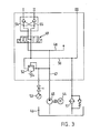
- the pressure network is fed by a hydraulic pump 45 driven by a motor 44, which sucks the pressure medium from a container 46 and conveys it into a pressure line 47 , in which a branch 48 can serve to act on other hydraulic units.
- a 4/3-way valve 49 is connected to the pressure line 47, in which the lines 30, 31 are connected to two further connections, while a pressure-free return line 50 connects to the fourth connection and opens into the container 46 via a pressure-protected filter 51.
- the standstill of the system corresponds to the illustration in FIGS. 2 and 3.
- the directional control valve 49 is in the middle position in which the lines 30, 31 are connected to the outlet, ie to the return line 50.
- the control lines of the check valves 54, 55 set to drain so that these valves are closed. This means that no pressure medium can run off and the agitator 13 thus remains in the set position.
- the directional control valve 49 is shifted into the right position.
- the printing network, i.e. line 47 is connected to line 31, while line 30 is set to expire.
- the agitator 13 is raised into its upper position by the linear motor 10.
- the directional valve 49 is moved to the left.
- the pressure set in the pressure control valve 32 builds up in line 30, while the line 31 sets the pressure set by pressure-maintaining valve 34. If the forces acting on the agitator 13 are in equilibrium, it stops. Now either the pressure in line 30 can be increased or the pressure in line 31 can be reduced so that the agitator 13 moves downward. If the agitator arms 19 move up on the filter cake, the downward movement of the agitator 13 is braked and, as a result, a certain force is exerted on the filter cake, as a result of which the rotating agitator arms smooth the cake surface.
- the rotating agitator moves to the cake level and always presses on the cake surface with the same smoothing pressure. If the back pressure on the stirrer arms 19 increases due to the filter cake growing, the effective weight of the stirrer is reduced, so that the pressure in the line 31 and the pressure flowing through the connecting line 39 medium the agitator is raised until the balance of forces is reached again, etc.
- FIGS. 2 and 3 groups of hydraulic elements are surrounded by a rectangle drawn in broken lines.
- the hydraulic cylinder 8, see FIG. 1 is constructed on the housing 2, while the assemblies according to FIGS. 2 and 3 can be constructed, for example, on the pump unit, which usually forms a unit with the container, the drive motor and other components.
- the valves and throttles are marked as controllable by an arrow. However, it depends on the practical operating conditions of the Nutsche filter whether valves are fixed or remain adjustable.
Abstract
Description
Die Erfindung betrifft einen Filter zum Trennen von Feststoffen aus Flüssigkeiten und zur Behandlung des sich mit den Feststoffen auf der Filterfläche bildenden Filterkuchens, in dessen Gehäuse ein Rührwerk eingebaut ist, welches mit einem Motor für die Drehbewegung und mit mindestens einem Linearmotor in Form eines hydraulischen Zylinders ausgerüstet ist, bei welch letzterem der Kolben für die Aufwärts- und Abwärtsbewegung durch das Druckmedium einer Druckquelle beaufschlagbar ist.The invention relates to a filter for separating solids from liquids and for treating the filter cake formed with the solids on the filter surface, in the housing of which an agitator is installed, which has a motor for the rotary movement and at least one linear motor in the form of a hydraulic cylinder is equipped, in the latter of which the piston can be acted upon by the pressure medium of a pressure source for the upward and downward movement.
.Es ist bekannt, bei Filtern zum Trennen von Feststoffen aus Flüssigkeiten, insbesondere bei Filternutschen, über dem Filterboden ein Rührwerk vorzusehen, welches für verschiedene Zwecke einsetzbar ist. Das Rührwerk besteht im wesentlichen aus einer rotierbaren sowie heb- und senkbaren Antriebswelle, an deren Ende zwei oder mehr Rührwerkarme befestigt sind. Je nach der Drehrichtung und/oder der Hebe- oder Snkbewegung können zusätzliche Operationen ausgeführt werden.It is known to provide an agitator for filters for separating solids from liquids, in particular for filter chutes, which can be used for various purposes. The agitator consists essentially of a rotatable as well as a raised and lowered drive shaft, at the end of which two or more agitator arms are attached. Depending on the direction of rotation and / or the lifting or snaking movement, additional operations can be carried out.
Eine wesentliche Operation, die das Rührwerk ausführen soll, besteht in dem Glattstreichen des sich auf dem Filterboden bildenden Filterkuchens. Es ist nicht zu vermeiden, dass während der Filteroperation der Filterkuchen sich nicht gleichmässig aufbaut, sondern Risse bilden kann. Hier hat das Rührwerk die Aufgabe, den Filterkuchen glattzustreichen, so dass sich die Risse im Filterkuchen schliessen. Dadurch wird eine gleichmässige Durchlässigkeit des Filterkuchens gewährleistet.An essential operation that the agitator is supposed to perform is to smooth the surface of the filter base forming filter cake. It cannot be avoided that the filter cake does not build up evenly during the filter operation, but that cracks can form. Here the agitator has the task of smoothing out the filter cake so that the cracks in the filter cake close. This ensures uniform permeability of the filter cake.
Für das Glattstreichen des Filterkuchens ist es erforderlich, einen bestimmten Druck auf denselben auszuüben. Weiter soll dieser Druck in gleicher Stärke und unabhängig vom Wachsen oder Schrumpfen des Filterkuchens ausgeübt werden.To smooth the filter cake, it is necessary to exert a certain pressure on it. Furthermore, this pressure should be applied with the same strength and regardless of the waxing or shrinking of the filter cake.
In dem praktischen Betrieb ist es schwierig,die erwähnten Forderungen zu verwirklichen. Man behilft sich deshalb dadurch, dass die Bedienungsperson für die Filternutsche das Glattstreichen des Filterkuchens derart nachregelt, dass entsprechend dem Wachsen oder Schrumpfen des Filterkuchens der Druckdes Rührwerkes annähernd konstant bleibt. Diese manuelle Einstellung des Rührwerkes ist jedoch zeitraubend, so dass die Bedienungsperson von andern Aufgaben entlastet werden muss, da sie die Filtrationsoperation dauernd beobachten muss. Dies kann zudem durch eine schlechte Beobachtbarkeit, z.B. durch ein angelaufenes oder verschmutztes Schauglas, zusätzlich erschwert werden.In practice, it is difficult to meet the requirements mentioned. It is therefore helped that the operator for the filter chutes adjusts the smoothing of the filter cake in such a way that the pressure of the agitator remains approximately constant as the filter cake grows or shrinks. However, this manual adjustment of the agitator is time-consuming, so that the operator has to be relieved of other tasks, since he has to constantly monitor the filtration operation. This can also be due to poor observability, e.g. a tarnished or dirty sight glass can make it even more difficult.
Hier setzt die Erfindung ein, der die Aufgabe zugrundeliegt, einen Filter der eingangs beschriebenen Art so weiter auszugestalten, dass die Funktion des Rührwerkes bei einer Filteroperation über längere Zeit unbeobachtet gelassen werden kann und damit der Filter in einen automatisch gesteuerten Prozessablauf integriert werden kann.This is where the invention comes in, which is based on the object of further developing a filter of the type described at the outset in such a way that the function of the agitator can be left unobserved for a long time during a filter operation and the filter can thus be integrated into an automatically controlled process flow.
Diese Aufgabe wird gemäss der Erfindung dadurch gelöst, dass für die Abwärtsbewegung des Rührwerkes die eine Kolbenseite des Linearmotors über eine erste Leitung durch einen von einem Druckregelventil geregelten konstanten Druck des Druckmediums beaufschlagt ist, während für die Einstellung des Druckes auf der andern Kolbenseite des Linearmotors diese Seite mit einer ein Druckhalteventil aufweisenden zweiten Leitung verbunden ist.This object is achieved according to the invention in that for the downward movement of the agitator, one piston side of the linear motor is acted upon via a first line by a constant pressure of the pressure medium regulated by a pressure control valve, while for the adjustment of the pressure on the other piston side of the linear motor, this Side is connected to a second line having a pressure holding valve.
Die Erfindung ist in der Zeichnung in einem Ausführungsbeispiel dargestellt und nachfolgend beschrieben. Es zeigen:
- Fig. 1 einen Querschnitt eines schematisch dargestellten Nutschenfilters,
- Fig. 2 ein Schaltschema der Steuerung des Linearmotors für die Hebe- und Senkbewegung des Rührwerkes eines Nutschenfilters nach Fig. 1 und
- Fig. 3 das Schaltschema der Druckquelle und der dazugehörigen Schaltelemente für die Steuerung nach Fig. 2.
- 1 shows a cross section of a schematically illustrated Nutsche filter,
- F ig. 2 is a circuit diagram of the control of the linear motor for the lifting and lowering movement of the agitator of a Nutsche filter according to FIGS. 1 and
- 3 shows the circuit diagram of the pressure source and the associated switching elements for the control according to FIG. 2.
Die Erfindung wird nachstehend am Beispiel eines Nutschenfilters für Druckbetrieb bekannter Bauart beschrieben, wie es in Fig. 1 schematisch dargestellt ist. Die Erfindung ist jedoch in ihrer Anwendung nicht nur auf Druckfilter beschränkt, sondern kann auch bei offenen Filtern und solchen mit Vakuumbetrieb eingesetzt werden.The invention is described below using the example of a Nutsche filter for printing operation of a known type, as is shown schematically in FIG. 1. However, the application of the invention is not limited to pressure filters, but can also be used with open filters and those with vacuum operation.
Das in Fig. 1 gesamthaft mit 1 bezeichnete Nutschenfilter weist ein Gehäuse 2 auf, das im allgemeinen zylinderförmig ausgebildet und durch einen waagrecht angeordneten Boden 3 abgeschlossen ist; dieser kann entweder mit dem Gehäuse 2 lösbar oder nichtlösbar verbunden sein. In der Gehäusewand ist ein Verschluss 4 vorgesehen, durch welchen der sich im Innern des Gehäuses 2 bildende Filterkuchen entfernt werden kann. Durch einen auf der Deckelpartie des Gehäuses 2 angebrachten Leitungsanschluss 6 kann beispielsweise die zu filtrierende Trübe oder Suspension in das Gehäuseinnere eingebracht werden. Weiter kann (nicht dargestellt) ein Anschluss für die Einführung eines Druckmediums, z.B. Stickstoff o.dgl., vorgesehen sein.The Nutsche filter, designated overall by 1 in FIG. 1, has a
Auf dem Boden 3 des Gehäuses 2 ist eine Filterfläche angeordnet, die mit einem Filtermittel, beispielsweise einem Filtertuch, einem Sieb oder einer festen, porösen Platte, belegt ist.A filter surface is arranged on the
Auf der Deckelpartie des Gehäuses 2 ist eine Hubvorrichtung aufgebaut, welche sich aus zwei Linearmotoren 10, z.B. Hydraulik-Zylinder, zusammensetzt. Die Linearmotoren 10 sind mittels einer Verbindungsplattform 11 miteinander verbunden und sind auf Sockeln 12 befestigt, welche auf der Deckelpartie des Gehäuses 2 abgestützt sind. Zudem ist die Verbindungsplattform 11 von Führungssäulen 56 geführt.A lifting device is constructed on the cover part of the
Auf der Verbindungsplattform 11 ist ein Motor 14, beispielsweise ein elektrischer Getriebemotor fest gelagert, an dessen Antriebswelle 15 eine Rührerwelle 16 eines Rührwerkes 13 mit einer Kupplung 17 gekuppelt ist. Am untern Ende der Rührerwelle 16 ist ein Rührer 18 befestigt, der beispielsweise zwei Rührarme 19 aufweist.A
Anstelle der beiden Linearmotoren 10 kann auch nur ein einziger Linearmotor 10 in Form eines Hydraulik-Zylinders 8 verwendet werden, siehe Fig. 2. Bei dieser Anordnung ist der Motor 14 für die Erzeugung der Drehbewegung des Rührerwerkes 13 mittels eines auskragenden Tragarmes 20 mit der Kolbenstange des Linearmotors 10 verbunden.Instead of the two
Unter dem Boden 3 ist ein als Hohlraum ausgebildeter Filterablauf 21 vorgesehen, aus welchem das Filtrat durch einen im Zentrum angeordneten Ablaufstutzen 22 abgeleitet werden kann. Der Boden 3 ist am Aussenumfang durch eine ringförmige Wand 24 begrenzt und ist durch Stege 26 aus einem Doppel-T-Profil abgestützt.Provided under the
Das Rührwerk 13 hat je nach dem zu verarbeitenden Produkt unterschiedliche Funktionen auszuüben, von denen der Behandlung des Filterkuchens besondere Bedeutung zukommt. Der sich auf dem Filtermittel bildende Filterkuchen schrumpft zusammen, wenn ihm das Filtrat entzogen wird. Dadurch entstehen Risse im ganzen Filterkuchen, welche sich bis zum Filtermittel erstrecken können. Im Druckbetrieb eines Nutschenfilters kann das zur Druckbeaufschlagung eingeleitete Gas durch diese Risse entweichen, ohne die gewünschte Wirkung ausgeübt zu haben. Zudem bewirken die Risse, dass der Filtei kuchen beim Waschen und Trocknen nicht gleichmässig von der Waschflüssigkeit bzw. von der Druckluft durchströmt wird. Eine der Funktionen des Rührwerkes 13 besteht im Glattstreichen des Filterkuchens, damit sich die Risse schliessen und dadurch eine gleichmässige Durchlässigkeit des Filterkuchen: erreicht wird. Durch den vom Rührwerk 13 ausgeübten Druck wird der Filterkuchen zusätzlich ausgepresst. Zum Glattstre: chen der Oberfläche des Filterkuchens sind die Rührarme 19 zweckmässig kufenartig ausgebildet.The
Damit dieses Glattstreichen des Filterkuchens mit konstantem Druck selbsttätig durchgeführt werden kann, ist die in Fig. 2 beschriebene hydraulische Steuerung vorgesehen, mit welcher der als Hydraulikzylinder 8 ausgebildete Linearmotor 10 beaufschlagt wird, dessen Kolbenstange 9 die das Rührwerk 13 tragende Plattform 11 bzw. den Tragarm 20 stützt.So that this smoothing of the filter cake can be carried out automatically at constant pressure, the hydraulic control described in FIG. 2 is provided, with which the
Der Hydraulikzylinder 8 ist auf seiner kolbenstangenseitigen Kolbenseite mit einer ersten Leitung 31 und auf der andern, kolbenstangenfreien Seite mit einer zweiten Leitung 31 verbunden. An die Leitung 31 ist ein Druckregelventil 32 angeschlossen, mit dem ein konstanter Druck in der Leitung 31 einstellbar und mit einem Druckmesser 33 messbar ist. In der Leitung 31 ist ein Druckhalteventil 34 angeschlossen, das den Druck vor diesem Ventil unabhängig von der durchfliessenden Menge konstant hält. In der Leitung 31 ist parallel zum Druckhalteventil 34 ein Rückschlagventil 35 angeordnet, das beim Anheben des Rührwerkes 13 sich öffnet, im Glattsteichbetrieb jedoch geschlossen ist.The hydraulic cylinder 8 is connected to a
Mit den beiden Ventilen 32, 34 kann ein konstanter Druck mit dem Rührwerk 13 dadurch ausgeübt werden, dass auf den beiden Kolbenseiten bzw. in den Leitungen 30, 31 ein konstanter Druck eingestellt wird, so dass ein konstantes Druckgefälle zwischen den Leitungen 30, 31 besteht. Die beim Glattstreichen des Filterkuchens von den Rührarmen 19 ausgeübte Presskraft setzt sich aus dem Rührwerkgewicht und dem durch den Druck in der Leitung 30 auf die kolbenstangenseitige Kolbenfläche ausgeübte Kraft sowie den entgegengesetzt wirkenden Kräften zusammen, welch letztere sich ihrerseits aus der Reibung einer die Rührwelle 16 abdichtenden Stopfbüchse 23, dem auf-- die Rührerwelle 16 wirkenden Behälterdruck und dem auf die kolbenfreie Kolbenfläche des Zylinders 8 wirkenden Druck der Leitung 31 zusammen. Solange die Stärke des Filterkuchens nur wenig wächst, bleibt auch die vom Rührwerk 13 beim Glattstreichen der Filterkuchenoberfläche auf den Filterkuchen ausgeübte Presskraft annähernd konstant. Wenn.jedoch der Filterkuchen stärker wächst, verändert sich dieser Pressdruck und muss dann durch Beaufschlagen der Leitung 31 mit Druckmedium korrigiert werden. Dieses Nachstellen des Pressdruckes kann in einfacher Weise dadurch vermieden werden, wenn in den Leitungen 30, 31 Abzweigungen 37, 38 vorgesehen werden, die durch eine mit einem Drosselventil 40 und einem Rückschlagventil 41 versehene Leitung 39 miteinander verbunden werden. Da beim Glattstreichen des Filterkuchens mit dem Rührwerk 13 in der Leitung 30 ein höherer Druck herrscht als in der Leitung 31 fliesst Druckmedium aus der Leitung 30 in die Leitung 31. Wird nun durch das Wachsen der Stärke des Filterkuchens ein Rückdruck auf das Rührwerk ausgeübt, wird der Kolben 8 etwas entlastet, wodurch Druckmedium durch die Leitung 39 so lange nachfliesst, bis das eingestellte Druckgefälle sich wieder bei einer höheren Lage der Rührarme 19 einstellt. Auf diese Weise wird erreicht, dass unabhängig von der Art und der Ausbildung des Filterkuchens der eingestellte Druck des Rührwerkes 13 beim Glattstreichen während einer ganzen Filteroperation konstant bleibt.With the two
In der Steuerung nach Fig. 2 ist für die Leitung 31 ein Druckmesser 36 vorgesehen, während in den Leitungen 30, 31 je ein Drosselrückschlagventil 42, 43 vorgesehen, bei denen das Rückschlagventil bei Druckmediumfluss gegen den Zylinder 8 öffnet. Schwingungen die hauptsächlich bei kleiner Sinkgeschwindigkeit im Hydraulik-System auftreten können, kann man dadurch entgegenwirken, dass der Druck in der Leitung 31 mit Hilfe des Druckregelventils 32 auf den tiefstmöglichen Wert verringert wird.2, a
Das gesamte Hydraulik-System ergibt sich aus Fig. 2 und 3. Die Verbindungsstellen sind durch die römischen Zahlen I, II und III bezeichnet. Hierbei stellen I, II den Anschluss der Leitungen 30, 31 an das Drucknetz nach Fig. 3 dar. Das Drucknetz wird von einer, durch einen Motor 44 angetriebenen Hydropumpe 45 gespeist, welche das Druckmedium aus einem Behälter 46 ansaugt und in eine Druckleitung 47 fördert, bei der eine Abzweigung 48 für die Beaufschlagung anderer Hydroaggregate dienen kann. An der Druckleitung 47 ist ein 4/3-Wegeventil 49 angeschlossen, bei dem an zwei weitere Anschlüsse die Leitungen 30, 31 angeschlossen sind, während am vierten Anschluss eine drucklose Rücklaufleitung 50 anschliesst, welche über ein druckgesichertes Filter 51 in den Behälter 46 mündet. In die Leitung 50 münden auch Rückleitungen des Druckregelventils 32 (bei III) und eines Druckregelventils 52, mit welchem der Druck in der Druckleitung 47 geregelt und an einem Druckmesser 53 angezeigt wird. Im weitern ist in den Leitungen 30, 31 zwischen den Drosselrückschlagventilen 42, 43 und dem Wegeventil 49 je ein druckgesteuertes Rückschlagventil 54, 55 angeordnet. Das Ventil 54 wird hierbei durch den Druck in der Zuleitung der Leitung 31 und das Ventil 55 durch den Druck in der Zuleitung der Leitung 30 geöffnet.The entire hydraulic system results from FIGS. 2 and 3. The connection points are designated by the Roman numerals I, II and III. I, II represent the connection of the
Die beschriebene Steuerung nach Fig. 2 und 3 arbeitet wie folgt:The control described in FIGS. 2 and 3 works as follows:
Der Stillstand der Anlage entspricht der Darstellung in Fig. 2 und 3. Das Wegeventil 49 befindet sich in der mittleren Stellung, in welcher die Leitungen 30, 31 mit dem Ablauf, d.h. mit der Rückleitung 50, verbunden sind. Dadurch werden auch die Steuerleitungen der Rückschlagventile 54, 55 auf Ablauf gestellt, so dass diese Ventile geschlossen sind. Dies bedeutet, dass kein Druckmedium ablaufen kann und somit das Rührwerk 13 in der eingestellten Lage verbleibt.The standstill of the system corresponds to the illustration in FIGS. 2 and 3. The
Hierzu wird das Wegeventil 49 in die rechte Lage verschoben. Das Drucknetz, d.h. die Leitung 47 ist mit der Leitung 31 verbunden, während die Leitung 30 auf Ablauf gestellt ist. Dadurch wird dass Rührwerk 13 durch den Linearmotor 10 in seine obere Lage angehoben.For this purpose, the
Hierzu wird das Wegeventil 49 nach links bewegt. Der im Druckregelventil 32 eingestellte Druck baut sich in der Leitung 30 auf, während sich in der Leitung 31 der durch das Druckhalteventil 34 eingestellte Druck einstellt. Sind die am Rührwerk 13 wirkenden Kräfte im Gleichgewicht, bleibt es stehen. Nun kann entweder der Druck in der Leitung 30 erhöht oder der Druck in der Leitung 31 gesenkt werden, damit das Rührwerk 13 sich abwärts bewegt. Fahren die Rührarme 19 auf dem Filterkuchen auf, wird die Abwärtsbewegung des Rührwerkes 13 gebremst und dadurch eine gewisse Kraft auf den Filterkuchen ausgeübt, wodurch die drehenden Rührwerkarme die Kuchenoberfläche glatt streichen. Schrumpft der Filterkuchen wegen Entzug von Filtrat, fährt das sich drehende Rührwerk dem Kuchenniveau nach und drückt immer mit demselben Glattstreichdruck auf die Kuchenoberfläche. Steigt durch Anwachsen des Filterkuchens der Rückdruck auf die Rührarme 19, wird das wirksame Gewicht des Rührwerkes verringert, so dass durch den Druck in der Leitung 31 und durch das durch die Verbindungsleitung 39 strömende Druckmedium das Rührwerk so lange angehoben wird, bis wieder das Gleichgewicht der Kräfte erreicht ist, usf.For this purpose, the
Mit der beschriebenen Glattstreichautomatik für das Rührwerk 13 kann der Einsatzbereich von Nutschenfiltern erweitert werden, da der Bedienungsaufwand für das Nutschenfilter wesentlich verringert wird. Die Mittel zur Erreichung dieser Automatik sind recht einfach und zudem kann sie Trüben und Suspensionen mit unterschiedlichen Feststoffen und Feststoffmengen leicht angepasst werden.With the automatic smoothing function described for the
In den Figuren 2 und 3 sind Gruppen von Hydraulikelementen durch ein strichpunktiert gezogenes Rechteck umgeben. Der Hydraulikzylinder 8 ist, siehe Fig. 1 auf dem Gehäuse 2 aufgebaut, während die Baugruppen nach Fig. 2 und 3 beispielsweise auf dem Pumpenaggregat, das gewöhnlich mit dem Behälter, dem Antriebsmotor und weiteren Komponenten eine Einheit bildet, aufgebaut sein kann. In den Figuren 2 und 3 sind die Ventile und Drosseln durch einen Pfeil als regelbar gekennzeichnet. Es hängt aber von den praktischen Einsatzbedingungen des Nutschenfilters ab, ob Ventile fest eingestellt werden oder einstellbar bleiben.In FIGS. 2 and 3, groups of hydraulic elements are surrounded by a rectangle drawn in broken lines. The hydraulic cylinder 8, see FIG. 1, is constructed on the
Claims (7)
Applications Claiming Priority (2)
| Application Number | Priority Date | Filing Date | Title |
|---|---|---|---|
| CH990/86 | 1986-03-11 | ||
| CH990/86A CH675364A5 (en) | 1986-03-11 | 1986-03-11 |
Publications (3)
| Publication Number | Publication Date |
|---|---|
| EP0236784A2 true EP0236784A2 (en) | 1987-09-16 |
| EP0236784A3 EP0236784A3 (en) | 1988-11-23 |
| EP0236784B1 EP0236784B1 (en) | 1991-09-04 |
Family
ID=4199898
Family Applications (1)
| Application Number | Title | Priority Date | Filing Date |
|---|---|---|---|
| EP19870102098 Expired - Lifetime EP0236784B1 (en) | 1986-03-11 | 1987-02-14 | Filter for the separation of solids from liquids |
Country Status (5)
| Country | Link |
|---|---|
| US (1) | US4975183A (en) |
| EP (1) | EP0236784B1 (en) |
| JP (1) | JPS62213814A (en) |
| CH (1) | CH675364A5 (en) |
| DE (1) | DE3772595D1 (en) |
Cited By (1)
| Publication number | Priority date | Publication date | Assignee | Title |
|---|---|---|---|---|
| CN112807859A (en) * | 2021-01-14 | 2021-05-18 | 邵兵 | Cleaning equipment for kitchen range hood |
Families Citing this family (7)
| Publication number | Priority date | Publication date | Assignee | Title |
|---|---|---|---|---|
| US6569480B2 (en) | 2001-04-30 | 2003-05-27 | Donald R. Hall | Liquefied gas extraction process |
| US20040050802A1 (en) * | 2002-05-17 | 2004-03-18 | Banister John Patrick | Fluid bed filter-dryer apparatus |
| CA2412613A1 (en) * | 2002-11-22 | 2004-05-22 | Mcn Bioproducts Inc. | Filtration of viscous oilseed slurries |
| ATE380060T1 (en) * | 2004-05-23 | 2007-12-15 | Rosenmund Vta Ag | METHOD AND DEVICE FOR REMOVAL OF RESIDUAL PRODUCTS |
| ITUB20152211A1 (en) * | 2015-07-15 | 2017-01-15 | Delta Costruzioni Mecc S R L | DEVICE AND METHOD TO SEPARATE THE SOLID FRACTION FROM THE LIQUID FRACTION OF A TURBID |
| CN108854221B (en) * | 2018-06-26 | 2020-07-14 | 中国科学院广州能源研究所 | Solid-liquid separation device and method for washing lignocellulose solid residues |
| US11911719B2 (en) * | 2019-09-20 | 2024-02-27 | Massachusetts Institute Of Technology | Devices and methods for the integrated filtration, drying, and mechanical processing of active pharmaceutical ingredients |
Citations (3)
| Publication number | Priority date | Publication date | Assignee | Title |
|---|---|---|---|---|
| US4081381A (en) * | 1975-09-24 | 1978-03-28 | Rosenmund Ag | Filtering apparatus |
| GB2084890A (en) * | 1980-09-19 | 1982-04-21 | Nippon Dyeing Machine Mfg Co | Filtering and drying apparatus |
| CH647685A5 (en) * | 1983-10-18 | 1985-02-15 | Rosenmund Ag | FILTER CHUTE. |
Family Cites Families (2)
| Publication number | Priority date | Publication date | Assignee | Title |
|---|---|---|---|---|
| SU689703A1 (en) * | 1977-03-09 | 1979-10-05 | Государственный Союзный Институт По Проектированию Производств Органического Синтеза | Nutsch filter |
| FR2454321A1 (en) * | 1979-04-19 | 1980-11-14 | Laderach Paul | Filter incorporating washing of cake and re-suspension in liq. - comprises mechanisms for equalising cake surface and filling up cracks and for stirring cake during re-suspension |
-
1986
- 1986-03-11 CH CH990/86A patent/CH675364A5/de not_active IP Right Cessation
-
1987
- 1987-02-14 EP EP19870102098 patent/EP0236784B1/en not_active Expired - Lifetime
- 1987-02-14 DE DE8787102098T patent/DE3772595D1/en not_active Expired - Fee Related
- 1987-03-06 JP JP62050437A patent/JPS62213814A/en active Pending
- 1987-03-06 US US07/022,741 patent/US4975183A/en not_active Expired - Fee Related
Patent Citations (3)
| Publication number | Priority date | Publication date | Assignee | Title |
|---|---|---|---|---|
| US4081381A (en) * | 1975-09-24 | 1978-03-28 | Rosenmund Ag | Filtering apparatus |
| GB2084890A (en) * | 1980-09-19 | 1982-04-21 | Nippon Dyeing Machine Mfg Co | Filtering and drying apparatus |
| CH647685A5 (en) * | 1983-10-18 | 1985-02-15 | Rosenmund Ag | FILTER CHUTE. |
Cited By (1)
| Publication number | Priority date | Publication date | Assignee | Title |
|---|---|---|---|---|
| CN112807859A (en) * | 2021-01-14 | 2021-05-18 | 邵兵 | Cleaning equipment for kitchen range hood |
Also Published As
| Publication number | Publication date |
|---|---|
| JPS62213814A (en) | 1987-09-19 |
| DE3772595D1 (en) | 1991-10-10 |
| EP0236784B1 (en) | 1991-09-04 |
| EP0236784A3 (en) | 1988-11-23 |
| CH675364A5 (en) | 1990-09-28 |
| US4975183A (en) | 1990-12-04 |
Similar Documents
| Publication | Publication Date | Title |
|---|---|---|
| DE2616643C3 (en) | Process for the continuous thickening of flowing suspensions and device for carrying out the process | |
| DE2629151C2 (en) | Backwashable filter device | |
| EP0827767B1 (en) | Apparatus for dewatering sludges and similar substances | |
| DE1436296A1 (en) | Filter press | |
| DD290813A5 (en) | SEPARATOR FOR DISCONNECTING A TRUEBE | |
| DE2712715B2 (en) | Sorter for fiber suspensions | |
| DE1172201B (en) | Pressure filter press and method for dewatering wet, fine-grained material, such as coal sludge and the like. like | |
| DE2846630A1 (en) | DEVICE FOR LIFTING THE BOTTOM OF CANS | |
| EP0236784B1 (en) | Filter for the separation of solids from liquids | |
| DE1636183B1 (en) | Device for separating the liquid content of a fiber slurry | |
| DE3725528A1 (en) | MACHINE FOR PRESSING AND DRAINING OR FILTER | |
| DE19836843A1 (en) | Apparatus for hydraulic setting of the rolls of billet guide segments of a continuous casting installation comprises switching valves connecting the hydraulic cylinder units to pressure sources and sinks | |
| DE3009777C2 (en) | Device for mixing and homogenizing at least two media | |
| EP0226659B1 (en) | Filter press | |
| DE1761339B2 (en) | DEVICE FOR SEPARATING THE LIQUID CONTENT OF A FIBER SLURRY | |
| DD252766A5 (en) | FILTER PRESS | |
| DE2604010A1 (en) | HYDRAULIC DRIVE DEVICE FOR A CLAMPING DEVICE OF A HOBBING MACHINE | |
| WO1988000082A1 (en) | Rotary disc filter | |
| DE1627957A1 (en) | Continuously working press | |
| DE3635766C2 (en) | ||
| EP0138920A1 (en) | Plant for separating the liquid portion from the solid portion of a ceramic slime. | |
| EP0982058B1 (en) | Apparatus for de-watering sludge and similar substances | |
| CH515731A (en) | Device for cleaning pourable filter material in slow water treatment filters filled with water | |
| DE2434943A1 (en) | DEVICE FOR REMOVING LIQUID FROM A SUSPENSION | |
| DE2535984A1 (en) | DEVICE FOR REPLACING THE SEAL OF A SEALED DRIVE FOR AGITATORS |
Legal Events
| Date | Code | Title | Description |
|---|---|---|---|
| PUAI | Public reference made under article 153(3) epc to a published international application that has entered the european phase |
Free format text: ORIGINAL CODE: 0009012 |
|
| AK | Designated contracting states |
Kind code of ref document: A2 Designated state(s): BE DE FR GB IT NL |
|
| PUAL | Search report despatched |
Free format text: ORIGINAL CODE: 0009013 |
|
| AK | Designated contracting states |
Kind code of ref document: A3 Designated state(s): BE DE FR GB IT NL |
|
| 17P | Request for examination filed |
Effective date: 19890420 |
|
| 17Q | First examination report despatched |
Effective date: 19901123 |
|
| GRAA | (expected) grant |
Free format text: ORIGINAL CODE: 0009210 |
|
| AK | Designated contracting states |
Kind code of ref document: B1 Designated state(s): BE DE FR GB IT NL |
|
| ITF | It: translation for a ep patent filed |
Owner name: ING. A. GIAMBROCONO & C. S.R.L. |
|
| RAP4 | Party data changed (patent owner data changed or rights of a patent transferred) |
Owner name: ZWAG AG |
|
| REF | Corresponds to: |
Ref document number: 3772595 Country of ref document: DE Date of ref document: 19911010 |
|
| GBT | Gb: translation of ep patent filed (gb section 77(6)(a)/1977) | ||
| ET | Fr: translation filed | ||
| PGFP | Annual fee paid to national office [announced via postgrant information from national office to epo] |
Ref country code: FR Payment date: 19911223 Year of fee payment: 6 |
|
| PG25 | Lapsed in a contracting state [announced via postgrant information from national office to epo] |
Ref country code: GB Effective date: 19920214 |
|
| PG25 | Lapsed in a contracting state [announced via postgrant information from national office to epo] |
Ref country code: BE Effective date: 19920228 |
|
| PLBE | No opposition filed within time limit |
Free format text: ORIGINAL CODE: 0009261 |
|
| STAA | Information on the status of an ep patent application or granted ep patent |
Free format text: STATUS: NO OPPOSITION FILED WITHIN TIME LIMIT |
|
| 26N | No opposition filed | ||
| BERE | Be: lapsed |
Owner name: ZSCHOKKE WARTMANN A.G. Effective date: 19920228 |
|
| PG25 | Lapsed in a contracting state [announced via postgrant information from national office to epo] |
Ref country code: NL Effective date: 19920901 |
|
| GBPC | Gb: european patent ceased through non-payment of renewal fee | ||
| NLV4 | Nl: lapsed or anulled due to non-payment of the annual fee | ||
| PG25 | Lapsed in a contracting state [announced via postgrant information from national office to epo] |
Ref country code: DE Effective date: 19921103 |
|
| PG25 | Lapsed in a contracting state [announced via postgrant information from national office to epo] |
Ref country code: FR Effective date: 19931029 |
|
| REG | Reference to a national code |
Ref country code: FR Ref legal event code: ST |
|
| PG25 | Lapsed in a contracting state [announced via postgrant information from national office to epo] |
Ref country code: IT Free format text: LAPSE BECAUSE OF NON-PAYMENT OF DUE FEES;WARNING: LAPSES OF ITALIAN PATENTS WITH EFFECTIVE DATE BEFORE 2007 MAY HAVE OCCURRED AT ANY TIME BEFORE 2007. THE CORRECT EFFECTIVE DATE MAY BE DIFFERENT FROM THE ONE RECORDED. Effective date: 20050214 |