EP0236647A1 - Fluidized-bed heat generator with a device for ash removal and heat recovery - Google Patents
Fluidized-bed heat generator with a device for ash removal and heat recovery Download PDFInfo
- Publication number
- EP0236647A1 EP0236647A1 EP86402830A EP86402830A EP0236647A1 EP 0236647 A1 EP0236647 A1 EP 0236647A1 EP 86402830 A EP86402830 A EP 86402830A EP 86402830 A EP86402830 A EP 86402830A EP 0236647 A1 EP0236647 A1 EP 0236647A1
- Authority
- EP
- European Patent Office
- Prior art keywords
- hearth
- tubes
- generator according
- central
- volume
- Prior art date
- Legal status (The legal status is an assumption and is not a legal conclusion. Google has not performed a legal analysis and makes no representation as to the accuracy of the status listed.)
- Granted
Links
Images

Classifications
-
- F—MECHANICAL ENGINEERING; LIGHTING; HEATING; WEAPONS; BLASTING
- F22—STEAM GENERATION
- F22B—METHODS OF STEAM GENERATION; STEAM BOILERS
- F22B31/00—Modifications of boiler construction, or of tube systems, dependent on installation of combustion apparatus; Arrangements of dispositions of combustion apparatus
- F22B31/0007—Modifications of boiler construction, or of tube systems, dependent on installation of combustion apparatus; Arrangements of dispositions of combustion apparatus with combustion in a fluidized bed
- F22B31/0046—Modifications of boiler construction, or of tube systems, dependent on installation of combustion apparatus; Arrangements of dispositions of combustion apparatus with combustion in a fluidized bed for boilers of the shell type, e.g. with furnace box
- F22B31/0053—Modifications of boiler construction, or of tube systems, dependent on installation of combustion apparatus; Arrangements of dispositions of combustion apparatus with combustion in a fluidized bed for boilers of the shell type, e.g. with furnace box with auxiliary water tubes
Landscapes
- Engineering & Computer Science (AREA)
- Chemical & Material Sciences (AREA)
- Combustion & Propulsion (AREA)
- Physics & Mathematics (AREA)
- Thermal Sciences (AREA)
- Mechanical Engineering (AREA)
- General Engineering & Computer Science (AREA)
- Fluidized-Bed Combustion And Resonant Combustion (AREA)
- Devices And Processes Conducted In The Presence Of Fluids And Solid Particles (AREA)
- Crucibles And Fluidized-Bed Furnaces (AREA)
- Processing Of Solid Wastes (AREA)
- Physical Or Chemical Processes And Apparatus (AREA)
- Solid-Fuel Combustion (AREA)
- Gasification And Melting Of Waste (AREA)
- Medicines Containing Antibodies Or Antigens For Use As Internal Diagnostic Agents (AREA)
- Thermotherapy And Cooling Therapy Devices (AREA)
- Adhesives Or Adhesive Processes (AREA)
- Buildings Adapted To Withstand Abnormal External Influences (AREA)
- Cooling Or The Like Of Electrical Apparatus (AREA)
Abstract
Description
L'invention a pour objet un générateur thermique de puissance modérée à lit fluidisé comportant des moyens améliorés d'évacuation des centres et de récupération de chaleur, utilisable notamment pour des combustibles solides en particules (charbons, granulés d'ordures ménagères, etc...) ou pâteux (fractions lourdes pétrolières, boues résiduaires, etc...).The subject of the invention is a moderate power thermal generator with a fluidized bed comprising improved means for evacuating the centers and recovering heat, usable in particular for solid fuels in particles (coals, granules of household waste, etc.). .) or pasty (heavy petroleum fractions, residual sludge, etc.).
Un générateur de ce type fonctionnant selon la technique de combustion en lit fluidisé a l'avantage d'utiliser une gamme étendue de combustibles. Mais la réalisation d'un tel générateur pose des problèmes de construction et d'industrialisation liés à l'évacuation des centres et au traitraitement des fumées.A generator of this type operating according to the fluidized bed combustion technique has the advantage of using a wide range of fuels. However, the production of such a generator poses construction and industrialization problems linked to the evacuation of the centers and the treatment of the fumes.
Jusqu'à présent ces problèmes ont été résolus partiellement et de façon imparfaite ; les générateurs connus existants sont mal adaptés à la combustion de produits cendreux et ils nécessitent la mise en place de boîtes à fumées encombrantes et onéreuses.So far these problems have been solved partially and imperfectly; existing known generators are ill-suited to the combustion of ashy products and they require the installation of bulky and expensive smoke boxes.
Pour cette raison, les générateurs connus de construction monobloc ont une puissance faible ; les générateurs plus puissants utilisent généralement en association une ou plussieurs cellules à tubes d'eau (foyers), connectées à une cellule distincte à tubes de fumées, dont l'encombrement d'ensemble est par conséquent important. La préfabrication en usine et le montage de tels systèmes sont par ailleurs relativement longs.For this reason, known generators of monobloc construction have a low power; more powerful generators generally use in combination one or more cells with water tubes (fireplaces), connected to a separate cell with smoke tubes, the overall size of which is consequently large. The prefabrication in the factory and the assembly of such systems are also relatively long.
Le but principal de l'invention est de parvenir à un générateur du type indiqué ci-dessus avec lequel sont surmontées substantiellement sinon totalement les difficultés exposées ci-dessus, de façon simple et efficace.The main object of the invention is to achieve a generator of the type indicated above with which the difficulties set out above are overcome substantially if not totally, in a simple and effective manner.
Dans un générateur thermique utilisant un combustible solide ou pâteux comprenant un foyer central à paroi latérale et à grille de fluidisation pour contenir un lit fluidisé, une enveloppe périphérique creuse, à moyens d'arrivée et de sortie d'eau de circulation enveloppant le foyer central, un conduit de sortie de fumées relié au foyer central, selon l'invention cette enveloppe périphérique limite avec le foyer central au moins un volume intermédiaire qui est mis en communication avec le foyer central dans sa partie supérieure par des ouvertures pour fumées et qui est raccordé à sa partie inférieure à des tubes de fumées, par une première extrémité de ceux-ci ; ces tubes de fumée s'étendent dans l'enveloppe périphérique sur une partie substantielle de leur longueur et sont raccordés par leur seconde extrémité au conduit de sortie des fumées.In a thermal generator using a solid or pasty fuel comprising a central hearth with side wall and a fluidization grid to contain a fluidized bed, a hollow peripheral envelope, with means of arrival and exit of circulating water enveloping the central hearth, a smoke outlet duct connected to the central hearth, according to the invention, this peripheral envelope limits with the central hearth at least one intermediate volume which is placed in communication with the central hearth in its upper part by openings for smoke and which is connected at its lower part to smoke tubes, by a first end thereof; these smoke tubes extend in the peripheral envelope over a substantial part of their length and are connected by their second end to the smoke outlet duct.
Le volume intermédiaire ainsi créé est muni avantageusement à sa partie inférieure d'un collecteur de rassemblement et d'extraction des cendres entraînées par les fumées.The intermediate volume thus created is advantageously provided at its lower part with a collector for collecting and extracting the ash entrained by the fumes.
Le volume intermédiaire constitue un dépoussiéreur primaire qui est intégré au générateur en amont des tubes de fumées et qui protège ces tubes contre les risques d'encrassement et d'érosion prématurée. Cette disposition permet d'éviter l'utilisation d'une boîte à fumées qui est souvent réalisée par mécano-soudure et qui est rapportée à l'aide de brides surle générateur thermique.The intermediate volume constitutes a primary dust collector which is integrated into the generator upstream of the smoke tubes and which protects these tubes against the risks of fouling and premature erosion. This arrangement avoids the use of a smoke box which is often produced by mechanical welding and which is attached using flanges on the heat generator.
La compacité du générateur conforme à l'invention s'en trouve améliorée et la préfabrication en est facilitée.The compactness of the generator according to the invention is improved and the prefabrication is facilitated.
Selon une caractéristique particulière le foyer à lit fluidisé a au moins une paroi latérale à tubes d'eau entourée par l'enveloppe périphérique avec une disposition symétrique qui évite les problèmes de dilatation différentielle et de tenue dans le temps du générateur.According to a particular characteristic, the fluidized bed hearth has at least one side wall with water tubes surrounded by the peripheral envelope with a symmetrical arrangement which avoids the problems of differential expansion and resistance over time of the generator.
Selon une caractéristique plus particulière, la paroi verticale est composée de tubes d'eau réunis de manière étanche par des membranes ; ce mode de construction facilite la réalisation industrielle du générateur et améliore le transfert de chaleur.According to a more particular characteristic, the vertical wall is made up of water tubes joined in a sealed manner by membranes; this construction method facilitates industrial production of the generator and improves heat transfer.
Dans un exemple de réalisation de l'invention, la grille de fluidisation fait partie de l'enceinte remplie d'eau qui est mise en communication avec l'enveloppe périphérique. Cette conception permet un abaissement de la température de la grille, ce qui autorise sa fabrication en matériau économique. De plus, toutes les parois délimitant le lit fluidisé, y compris la grille elle-même, participent ainsi à l'échange thermique. Ceci permet de réduire les surfaces d'échange à immerger dans le lit ; il en résulte que les tubes constituant ces surfaces d'échange peuvent être disposés plus librement, en évitant les zones où se produirait une forte érosion.In an exemplary embodiment of the invention, the fluidization grid is part of the filled enclosure of water which is placed in communication with the peripheral envelope. This design allows a lowering of the temperature of the grid, which allows its manufacture in economical material. In addition, all the walls delimiting the fluidized bed, including the grid itself, thus participate in the heat exchange. This makes it possible to reduce the exchange surfaces to be immersed in the bed; it follows that the tubes constituting these exchange surfaces can be arranged more freely, avoiding the areas where a strong erosion would occur.
La grille de fluidisation mise en oeuvre dans le générateur thermique selon l'invention est en elle-même d'un type connu ; ce peut être en particulier une grille à ouvertures évasées vers le haut, telle que celles qui font l'objet des documents FR-A- Nos 2 171 945, 2 519 877, 85-08320, 85-15580.The fluidization grid used in the thermal generator according to the invention is in itself of a known type; this may in particular be a grid with openings flared upwards, such as those which are the subject of documents FR-A-
De préférence, une au moins des parois du foyer a une (ou plussieuurss) ouverture(s) munie(s) d'un moyen sélectif de fermeture ; cette ouverture permet de réguler le niveau du lit fluidisé.Preferably, at least one of the walls of the hearth has one (or more sieuurss) opening (s) provided (s) with a selective closing means; this opening makes it possible to regulate the level of the fluidized bed.
Selon une variante, le collecteur des cendres contient une boucle de circulation d'eau raccordée à l'enveloppe périphérique creuse. Cette boucle complète l'épuisement thermique des cendres et améliore encore le rendement de l'unité.According to a variant, the ash collector contains a water circulation loop connected to the hollow peripheral envelope. This loop completes the thermal exhaustion of the ashes and further improves the efficiency of the unit.
Selon une autre caractéristique particulière, le générateur possède un dispositif de réinjection des cendres collectées par un dépoussiéreur final (multicyclone par exemple) raccordé sur le circuit des fumées en sortie de chaudière.According to another particular characteristic, the generator has a device for re-injecting the ash collected by a final dust collector (for example a multi-cyclone) connected to the smoke circuit at the outlet of the boiler.
Ce dispositif permet ainsi d'améliorer la désulfuration in situ, de réduire les imbrûlés et de limiter les points d'extraction des cendres.This device thus makes it possible to improve the desulfurization in situ, to reduce unburnt residues and to limit the extraction points of the ashes.
Ce dispositif peut être réalisé, par exemple, par voie pneumatique, par une dérivation de l'arrivée d'air de fluidisation ou d'air secondaire ou par voie mécanique par convoyage à l'aide d'une vis transporteuse.This device can be produced, for example, pneumatically, bypassing the arrival of fluidizing air or secondary air or mechanically by conveying using a conveyor screw.
En complément de cette réinjection, il est possible de remplir les cendres recueillies au niveau du dépoussiéreur interne, en totalité ou en partie, par exemple comme moyen d'auto-alimentation du lit en matériaux inertes.In addition to this reinjection, it is possible to fill the ashes collected at the internal dust collector, in whole or in part, for example as a means of self-feeding the bed with inert materials.
On donnera maintenant, sans intention limitative et sans exclure aucune variante, une description d'un exemple de réalisation de l'invention. On se reportera aux dessins annexés dans lesquels :
- - la figure 1 est une représentation schématique en coupe par un plan vertical selon I-I de la figure 2 d'un générateur thermique conforme à l'invention ;
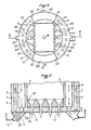
- - la figure 2 est une vue en coupe par un plan horizontal selon II-II de la figure 1,
- - la figure 3 est une vue partielle en coupe montrant une variante de réalisation de la partie inférieure du générateur de la figure 1.
- - Figure 1 is a schematic representation in section through a vertical plane along II of Figure 2 of a thermal generator according to the invention;
- FIG. 2 is a sectional view through a horizontal plane along II-II of FIG. 1,
- - Figure 3 is a partial sectional view showing an alternative embodiment of the lower part of the generator of Figure 1.
Un générateur conforme à l'invention comprend un foyer 1 à lit fluidisé, à paroi latérale, de type connu en soi et une enveloppe périphérique 2 qui enveloppe le foyer 1 en limitant avec la paroi latérale 3 de ce dernier un volume intermédiaire 4. Le foyer 1 pourrait être cylindrique ainsi que l'enveloppe périphérique 2, de sorte que le volume intermédiaire 4 serait un volume annulaire. A la partie supérieure du foyer 1, des ouvertures 5 le mettent en communication avec le volume intermédiaire 4.A generator according to the invention comprises a
Dans le présent exemple, comme le montre la figure 2, le foyer 1 a une configuration rectangulaire dans l'ensemble ; l'enveloppe périphérique 2 est cylindrique et elle limite avec le foyer 1 deux volumes intermédiaires 4A, 4B distincts et opposés qui sont situés chacun sur un grand côté du foyer 1. Les deux grands côtés 3A, 3B du foyer 1 sont constitués par des tubes d'eau 3C parallèles, espacés, reliés entre eux de façon étanche par des membranes intermédiaires 3D, de manière connue en soi. A la partie extrême supérieure du foyer 1 certains tubes, de préférence un tube sur deux, sont déportés vers l'extérieur du foyer 1 et les membranes intermédiaires 3D sont supprimées dans la partie extrême déportée de chaque tube 3C. On obtient ainsi les ouvertures supérieures 5 par lesquelles peuvent circuler les fumées qui proviennent du foyer 1.In the present example, as shown in FIG. 2, the
Dans l'exemple décrit ici, le foyer 1 est fermé à sa partie supérieure, à un niveau supérieur à celui des ouvertures 5, par une paroi supérieure 1A qui déborde en dehors du foyer 1 et qui ferme aussi les volumes intermédiaires 4A, 4B. Les fumées ne peuvent entrer dans ce dernier que par les ouvertures supérieures 5. En outre, du fait de l'existence de cette paroi supérieure 1A, l'enveloppe périphérique 2 couvre aussi le foyer 1 au-dessus de cette paroi supérieure 1A. De cette façon, l'enveloppe périphérique s'étend autour de la paroi latérale et de la paroi supérieure du foyer 1 ; elle enveloppe ce dernier complètement sur tous ses côtés. A son sommet, l'enveloppe périphérique 2 est fermée par une paroi supérieure 6. Cette dernière supporte un conduit de sortie des fumées 7.In the example described here, the
Dans le présent exemple, l'enveloppe périphérique 2 est divisée par des cloisons intérieures, radiales 6A, 6B, 6C, 6D formant quatre compartiments opposés deux à deux. Deux compartiments opposés, de plus grande dimension en sens circonférentiel 8A et 8C contiennent des tubes verticaux 9, espacés, qui s'étendent entre la paroi inférieure 10 de l'enveloppe périphérique 2 et sa paroi supérieure 6. Ces tubes 9 traversent cette paroi supérieure 6 et débouchent dans le conduit de sortie des fumées 7. A son extrémité opposée inférieure chaque tube 9 traverse la paroi inférieure 10 et débouche dans un collecteur de cendres 11. Un collecteur de cendres 11 est prévu sous chacun des deux compartiments 8A, 8C de l'enveloppe périphérique 2. Chaque collecteur 11 s'étend en-dessous de la paroi inférieure 10 et il communique par un passage inférieur 11A avec un volume intermédiaire correspondant 4A, 4B. Les fumées de la combustion qui viennent des passages supérieurs 5 descendent dans les volumes intermé diaires 4A, 4B, empruntent les collecteurs 11 et montent dans les tubes 9 pour atteindre le conduit de sortie des fumées 7.In the present example, the
Chaque collecteur 11 a une profondeur suffisante pour que des cendres s'y rassemblent sans que la circulation des fumées soit interrompue. En outre, comme représenté seulement sur la partie gauche de la figure 1, chaque collecteur 11 est équipé en 12 d'un moyen pneumatique connu en soi, d'extraction des cendres et de réintroduction de ces cendres à l'intérieur du lit fluidisé, pour assurer leur recyclage.Each
Les deux autres compartiments opposés 8B, 8D sont pourvus, respectivement, d'une arrivée d'eau 13 et d'une sortie d'eau 14. En outre, ces deux compartiments sont reliés directement, à travers le foyer 1, par des tubes d'eau 15 (visibles seulement sur la figure 1) qui sont noyés pendant le fonctionnement dans le lit 16 de matière combustible fluidisée. Au niveau supérieur souhaité que peut atteindre le lit 16, il est prévu dans la paroi latérale 3 du foyer 1 au moins une ouverture de trop plein 17, connue en soi, qui débouche dans un compartiment 4B de descente des fumées et des cendres entraînées avec celles-ci. Une canalisation 18 traverse de haut en bas le conduit de sortie des fumées 7, la paroi supérieure 6 de l'enveloppe périphérique 2, la paroi supérieure 1A du foyer 1 pour s'étendre à l'intérieur de ce dernier et s'arrêter au-dessus du niveau supérieur du lit fluidisé 16. Cette canalisation 18 sert à alimenter le foyer 1 en combustible. On remarquera que l'invention est compatible avec d'autres modes d'alimentation du foyer 1 en combustible. De préférence, la canalisation 18 est refroidie par une boucle de circulation d'eau forcée branchée en dérivation sur le circuit entrée/sortie d'alimentation générale.The two other
Sur la figure 1, la grille 19 est représentée comme une grille creuse ayant un volume intérieur 19A dans lequel débouchent les tubes d'eau 3, par leur extrémité inférieure. Ces tubes 3 sont donc réunis à l'enveloppe périphérique 2 au niveau de la grille 19. En variante, comme le montre la figure 3, la grille de fluidisation 19ʹ est de construction classique et elle repose sur une enceinte creuse 20 qui la supporte et dont le volume intérieur est mis en communication avec le volume intérieur de l'enveloppe périphérique 2. Bien entendu, cette enceinte creuse 20 est traversée de façon étanche par des tubes 21 qui alimentent en gaz de fluidisation les orifices habituels de la grille 19ʹ. Selon une autre variante, la grille est de construction classique ; elle n'est pas refroidie, ni supportée par une enceinte creuse refroidie.In FIG. 1, the
Dans les deux cas de la figure 1 où la grille 19 est creuse et de la figure 3 où la grille 19ʹ repose sur une enceinte creuse 20, on obtient pendant le fonctionnement un abaissement de la température moyenne de la grille, ce qui permet d'employer pour sa réalisation, une matière plus économique.In the two cases of FIG. 1 where the
Dans toutes les circonstances, même si on ne prévoit pas d'utiliser une grille creuse 19 ou une grille 19ʹ supportée par une enceinte creuse 20, il existe en un point inférieur de l'enveloppe périphérique 2 une entrée d'eau 22 et en un point supérieur une sortie d'eau 23. Pendant le fonctionnement, l'eau circule dans les tubes 3 qui constituent la paroi latérale du foyer 1 ; elle circule aussi le long de la paroi supérieure 1A du même foyer ; elle circule encore le long de la paroi extérieure qui limite le volume intermédiaire 4 et autour des tubes 9 où circulent les fumées ; elle circule en plus, de préférence à travers la grille creuse 19 ou à travers l'enceinte creuse 20 qui supporte la grille 19ʹ. De cette façon, la chaleur contenue dans les fumées et les cendres est récupérée. Il est possible, en outre, de placer dans la partie interne inférieure de chaque collecteur de cendres 11 une bouche 24 de circulation d'eau raccordée au volume intérieur de l'enveloppe périphérique 2 comme on peut le voir sur les figures 1 et 3.In all circumstances, even if it is not intended to use a
Ainsi, les calories contenues dans les cendres peuvent être récupérées en presque totalité. En même temps, les cendres sont recueillies sans moyens matériels encombrants et ont peut en disposer ensuite facilement, soit pour les évacuer définitivement, soit pour les recycler dans le lit fluidisé.Almost all of the calories in the ashes can be recovered. At the same time, the ashes are collected without bulky material means and can then be disposed of easily, either to dispose of them definitively or to recycle them in the fluidized bed.
Dans certaines circonstances, on peut être conduit à supprimer les tubes 15 qui traversent le lit fluidisé 16. Dans ce cas, les compartiments 8B, 8D peuvent être supprimés aussi ; l'enveloppe périphérique 2 devient alors une enveloppe unique entourant annulairement la paroi latérale du foyer 1. Ce dernier peut être cylindrique et le volume intermédiaire 4 peut aussi entourer annulairement la paroi latérale du foyer 1.Under certain circumstances, it may be necessary to eliminate the
Claims (12)
Priority Applications (1)
| Application Number | Priority Date | Filing Date | Title |
|---|---|---|---|
| AT86402830T ATE45794T1 (en) | 1985-12-18 | 1986-12-16 | FLUIDIZED BED HEAT GENERATOR WITH MEANS FOR ASH REMOVING AND HEAT RECOVERY. |
Applications Claiming Priority (2)
| Application Number | Priority Date | Filing Date | Title |
|---|---|---|---|
| FR8518764A FR2591722B1 (en) | 1985-12-18 | 1985-12-18 | FLUIDIZED BED THERMAL GENERATOR WITH IMPROVED ASH DISCHARGE AND HEAT RECOVERY MEANS |
| FR8518764 | 1985-12-18 |
Publications (2)
| Publication Number | Publication Date |
|---|---|
| EP0236647A1 true EP0236647A1 (en) | 1987-09-16 |
| EP0236647B1 EP0236647B1 (en) | 1989-08-23 |
Family
ID=9325923
Family Applications (1)
| Application Number | Title | Priority Date | Filing Date |
|---|---|---|---|
| EP86402830A Expired EP0236647B1 (en) | 1985-12-18 | 1986-12-16 | Fluidized-bed heat generator with a device for ash removal and heat recovery |
Country Status (18)
| Country | Link |
|---|---|
| US (1) | US4736711A (en) |
| EP (1) | EP0236647B1 (en) |
| JP (1) | JPS62175505A (en) |
| CN (1) | CN1008656B (en) |
| AT (1) | ATE45794T1 (en) |
| AU (1) | AU581160B2 (en) |
| CA (1) | CA1294499C (en) |
| DE (2) | DE236647T1 (en) |
| DK (1) | DK164715C (en) |
| ES (1) | ES2000154B3 (en) |
| FI (1) | FI865169A (en) |
| FR (1) | FR2591722B1 (en) |
| GR (2) | GR880300086T1 (en) |
| IN (1) | IN169114B (en) |
| NO (1) | NO162485C (en) |
| PT (1) | PT83940B (en) |
| YU (1) | YU46036B (en) |
| ZA (1) | ZA869456B (en) |
Cited By (1)
| Publication number | Priority date | Publication date | Assignee | Title |
|---|---|---|---|---|
| EP0398814A1 (en) * | 1989-05-19 | 1990-11-22 | CHARBONNAGES DE FRANCE, Etablissement public dit: | Particle evacuation device from a fluidised bed outside the fluidised bed vessel |
Families Citing this family (10)
| Publication number | Priority date | Publication date | Assignee | Title |
|---|---|---|---|---|
| SE459987B (en) * | 1987-12-23 | 1989-08-28 | Abb Stal Ab | SET TO COOL ASH AND POWER PLANT WITH A DEVICE RINSE |
| DE4005305A1 (en) * | 1990-02-20 | 1991-08-22 | Metallgesellschaft Ag | FLUIDIZED LAYER REACTOR |
| US5484476A (en) * | 1994-01-11 | 1996-01-16 | Electric Power Research Institute, Inc. | Method for preheating fly ash |
| US8523963B2 (en) * | 2004-10-12 | 2013-09-03 | Great River Energy | Apparatus for heat treatment of particulate materials |
| US7540384B2 (en) * | 2004-10-12 | 2009-06-02 | Great River Energy | Apparatus and method of separating and concentrating organic and/or non-organic material |
| US8579999B2 (en) * | 2004-10-12 | 2013-11-12 | Great River Energy | Method of enhancing the quality of high-moisture materials using system heat sources |
| US8062410B2 (en) | 2004-10-12 | 2011-11-22 | Great River Energy | Apparatus and method of enhancing the quality of high-moisture materials and separating and concentrating organic and/or non-organic material contained therein |
| US7275644B2 (en) * | 2004-10-12 | 2007-10-02 | Great River Energy | Apparatus and method of separating and concentrating organic and/or non-organic material |
| US7987613B2 (en) * | 2004-10-12 | 2011-08-02 | Great River Energy | Control system for particulate material drying apparatus and process |
| CN110864280B (en) * | 2018-08-28 | 2021-05-04 | 国家能源投资集团有限责任公司 | Reactor and apparatus for burning carbonaceous solid fuel and method for burning carbonaceous solid fuel |
Citations (6)
| Publication number | Priority date | Publication date | Assignee | Title |
|---|---|---|---|---|
| DE2029155A1 (en) * | 1969-06-12 | 1970-12-23 | ||
| EP0016607A1 (en) * | 1979-03-14 | 1980-10-01 | The British Petroleum Company p.l.c. | Fluidised bed combustor |
| EP0028458A2 (en) * | 1979-10-03 | 1981-05-13 | Sandfire (Proprietary) Limited | Fluidised-bed boilers |
| GB2077616A (en) * | 1980-06-10 | 1981-12-23 | Parkinson Cowan Appliances Ltd | Fluidised bed boiler |
| GB2109096A (en) * | 1981-07-24 | 1983-05-25 | Duncomb Wallace Walker | Locomotive boiler fired by fluidised bed combustion |
| EP0005964B1 (en) * | 1978-05-31 | 1984-03-07 | Deborah Fluidised Combustion Limited | Boiler and combustion means therefor |
Family Cites Families (12)
| Publication number | Priority date | Publication date | Assignee | Title |
|---|---|---|---|---|
| US1684201A (en) * | 1927-02-26 | 1928-09-11 | Pollock James | Boiler for utilizing fine coal |
| US2832320A (en) * | 1953-12-14 | 1958-04-29 | Thome Robert | Gas-fired boiler, more particularly for central heating plants |
| BE795348A (en) * | 1972-02-16 | 1973-05-29 | Charbonnages De France | GAS SUPPLY DEVICE FOR A FLUIDIZATION TREATMENT REACTOR |
| GB1513795A (en) * | 1976-04-14 | 1978-06-07 | Coal Ind | Boilers |
| GB1604999A (en) * | 1978-05-31 | 1981-12-16 | Deborah Fluidised Combustion | Boilers |
| GB2073910A (en) * | 1980-04-11 | 1981-10-21 | World Energy Resources Consult | Controls for fluidised bed burners |
| NZ197338A (en) * | 1980-06-10 | 1985-03-20 | Thorn Emi Energy Dev | Fluidised bed boiler |
| US4349969A (en) * | 1981-09-11 | 1982-09-21 | Foster Wheeler Energy Corporation | Fluidized bed reactor utilizing zonal fluidization and anti-mounding pipes |
| FR2519877B1 (en) * | 1982-01-20 | 1986-10-31 | Charbonnages De France | FLUIDIZING GRID AND COMBUSTION FIRE WITH LOWER AIR BLOW GRID AND METHOD FOR TREATING PARTICULATE MATERIAL IN A FLUIDIZING AND / OR DRIVING CHAMBER |
| FR2556075B1 (en) * | 1983-12-02 | 1988-08-19 | Charbonnages De France | COMBUSTION FIREPLACE FOR A FLUIDIZED BED BOILER |
| US4565184A (en) * | 1984-05-17 | 1986-01-21 | Collins Bruce H | Combustible particulate fuel heater |
| FR2582540B1 (en) * | 1985-06-03 | 1992-05-22 | Charbonnages De France | DEVICE FOR CONTROLLING THE SUPPLY OF FLUIDIZING GAS TO THE BLOWING OPENINGS OF A FLUIDIZING GRID AND GRID PROVIDED WITH SUCH A DEVICE |
-
1985
- 1985-12-18 FR FR8518764A patent/FR2591722B1/en not_active Expired
-
1986
- 1986-12-10 US US06/940,079 patent/US4736711A/en not_active Expired - Fee Related
- 1986-12-16 IN IN978/MAS/86A patent/IN169114B/en unknown
- 1986-12-16 ES ES86402830T patent/ES2000154B3/en not_active Expired
- 1986-12-16 AT AT86402830T patent/ATE45794T1/en active
- 1986-12-16 PT PT83940A patent/PT83940B/en not_active IP Right Cessation
- 1986-12-16 EP EP86402830A patent/EP0236647B1/en not_active Expired
- 1986-12-16 DE DE198686402830T patent/DE236647T1/en active Pending
- 1986-12-16 DE DE8686402830T patent/DE3665214D1/en not_active Expired
- 1986-12-17 YU YU216386A patent/YU46036B/en unknown
- 1986-12-17 DK DK608486A patent/DK164715C/en not_active IP Right Cessation
- 1986-12-17 NO NO865108A patent/NO162485C/en unknown
- 1986-12-17 CA CA000525603A patent/CA1294499C/en not_active Expired - Fee Related
- 1986-12-17 CN CN86108550A patent/CN1008656B/en not_active Expired
- 1986-12-17 FI FI865169A patent/FI865169A/en not_active Application Discontinuation
- 1986-12-17 ZA ZA869456A patent/ZA869456B/en unknown
- 1986-12-18 AU AU66791/86A patent/AU581160B2/en not_active Ceased
- 1986-12-18 JP JP61300185A patent/JPS62175505A/en active Pending
-
1988
- 1988-12-16 GR GR88300086T patent/GR880300086T1/en unknown
-
1989
- 1989-08-24 GR GR89400116T patent/GR3000135T3/en unknown
Patent Citations (6)
| Publication number | Priority date | Publication date | Assignee | Title |
|---|---|---|---|---|
| DE2029155A1 (en) * | 1969-06-12 | 1970-12-23 | ||
| EP0005964B1 (en) * | 1978-05-31 | 1984-03-07 | Deborah Fluidised Combustion Limited | Boiler and combustion means therefor |
| EP0016607A1 (en) * | 1979-03-14 | 1980-10-01 | The British Petroleum Company p.l.c. | Fluidised bed combustor |
| EP0028458A2 (en) * | 1979-10-03 | 1981-05-13 | Sandfire (Proprietary) Limited | Fluidised-bed boilers |
| GB2077616A (en) * | 1980-06-10 | 1981-12-23 | Parkinson Cowan Appliances Ltd | Fluidised bed boiler |
| GB2109096A (en) * | 1981-07-24 | 1983-05-25 | Duncomb Wallace Walker | Locomotive boiler fired by fluidised bed combustion |
Cited By (3)
| Publication number | Priority date | Publication date | Assignee | Title |
|---|---|---|---|---|
| EP0398814A1 (en) * | 1989-05-19 | 1990-11-22 | CHARBONNAGES DE FRANCE, Etablissement public dit: | Particle evacuation device from a fluidised bed outside the fluidised bed vessel |
| FR2647031A1 (en) * | 1989-05-19 | 1990-11-23 | Charbonnages De France | DEVICE FOR EXTRACTING PARTICLE MATERIAL FROM A FLUIDIZED BED OUTSIDE THE FLUIDIZATION ENCLOSURE |
| US5143697A (en) * | 1989-05-19 | 1992-09-01 | Charbonnages De France | Device for extracting particulate materials of a fluidized bed from the fluidization enclosure |
Also Published As
| Publication number | Publication date |
|---|---|
| AU6679186A (en) | 1987-06-25 |
| FI865169A0 (en) | 1986-12-17 |
| NO865108D0 (en) | 1986-12-17 |
| EP0236647B1 (en) | 1989-08-23 |
| IN169114B (en) | 1991-09-07 |
| AU581160B2 (en) | 1989-02-09 |
| GR3000135T3 (en) | 1990-11-29 |
| PT83940B (en) | 1993-02-26 |
| CN1008656B (en) | 1990-07-04 |
| DK608486A (en) | 1987-06-19 |
| PT83940A (en) | 1987-01-01 |
| DE236647T1 (en) | 1988-01-14 |
| DK608486D0 (en) | 1986-12-17 |
| CN86108550A (en) | 1987-07-29 |
| DK164715B (en) | 1992-08-03 |
| YU46036B (en) | 1992-12-21 |
| ES2000154B3 (en) | 1989-11-01 |
| DE3665214D1 (en) | 1989-09-28 |
| NO865108L (en) | 1987-06-19 |
| FI865169A (en) | 1987-06-19 |
| FR2591722B1 (en) | 1988-02-19 |
| ZA869456B (en) | 1987-08-26 |
| FR2591722A1 (en) | 1987-06-19 |
| NO162485C (en) | 1990-01-03 |
| JPS62175505A (en) | 1987-08-01 |
| DK164715C (en) | 1992-12-28 |
| US4736711A (en) | 1988-04-12 |
| ES2000154A4 (en) | 1987-12-16 |
| YU216386A (en) | 1989-12-31 |
| ATE45794T1 (en) | 1989-09-15 |
| NO162485B (en) | 1989-09-25 |
| CA1294499C (en) | 1992-01-21 |
| GR880300086T1 (en) | 1988-12-16 |
Similar Documents
| Publication | Publication Date | Title |
|---|---|---|
| EP0236647B1 (en) | Fluidized-bed heat generator with a device for ash removal and heat recovery | |
| FR2486223A1 (en) | HEAT EXCHANGER WITH FLUIDIZED BED | |
| FR2564747A1 (en) | METHOD AND MEANS FOR CONTROLLING THE OPERATION OF A RECYCLED FLUIDIZED BED REACTOR | |
| BE897104A (en) | VERTICAL HEAT EXCHANGE REGENERATOR INCINERATOR, | |
| EP0040557A1 (en) | Heating device with a heat-recovery system | |
| FR2581173A1 (en) | FLUIDIZED BED EXCHANGER FOR HEAT TRANSFER | |
| EP0119115A1 (en) | Heat generator for heating a fluid by heat exchange with a fluidized bed, and method for putting it into operation | |
| EP0099833A1 (en) | Device for the conversion and recovery of thermal energy | |
| CA2501713A1 (en) | Circulating fluidized bed reactor with separator and integrated acceleration duct | |
| FR2896709A1 (en) | Metal oxide particles and carbonated residues separator for carbonated residue combustion installation, has vertical deflector constituting two compartments, in which one of compartments comprises lateral deflector deviating path | |
| FR2675241A1 (en) | FLUIDIZED BED COMBUSTION ASSEMBLY. | |
| EP1910741B1 (en) | Modular fluidised bed reactor | |
| FR2657683A1 (en) | COMBUSTION ASSEMBLY WITH INCORPORATED PARTICULATE SEPARATOR AND FLUIDIZED BED. | |
| FR2850157A1 (en) | FLUIDIZED CIRCULATION BED REACTOR | |
| EP2435176B1 (en) | Method for the adjustable gas-tight transfer of solids to chambers having a different gas atmosphere | |
| EP0142388B1 (en) | High pressure fluidised bed coal gasifier | |
| EP1018584A1 (en) | Flue and flue block for realising such flue | |
| EP0607071A1 (en) | Heat exchanger with secondary fluid fed at the top through an overflow | |
| FR2535026A1 (en) | Boiler using wood or other solid combustible materials | |
| FR2930981A1 (en) | Fuel e.g. chipped wood, combustion boiler for heating e.g. building, has heat exchanger for exchanging heat between hot air and coolant, and pressurized air supply unit for supplying pressurized air below furnace or to base of furnace | |
| FR2556075A1 (en) | COMBUSTION FIREPLACE FOR A FLUIDIZED BED BOILER | |
| FR2681668A1 (en) | Circulating-fluidised-bed boiler hearth with internal separating wall | |
| FR2481783A1 (en) | ||
| FR2532404A1 (en) | Fluidised bed combustion chamber bottom | |
| FR2522114A1 (en) | Boiler burning solid fuel - has heat exchanger and fuel loading chamber in column |
Legal Events
| Date | Code | Title | Description |
|---|---|---|---|
| PUAI | Public reference made under article 153(3) epc to a published international application that has entered the european phase |
Free format text: ORIGINAL CODE: 0009012 |
|
| AK | Designated contracting states |
Kind code of ref document: A1 Designated state(s): AT BE CH DE ES GB GR IT LI LU NL SE |
|
| RAP1 | Party data changed (applicant data changed or rights of an application transferred) |
Owner name: INSTITUT FRANCAIS DU PETROLE Owner name: CHARBONNAGES DE FRANCE, ETABLISSEMENT PUBLIC DIT: |
|
| ITCL | It: translation for ep claims filed |
Representative=s name: INGG. GUZZI RAVIZZA |
|
| TCAT | At: translation of patent claims filed | ||
| 17P | Request for examination filed |
Effective date: 19871006 |
|
| TCNL | Nl: translation of patent claims filed | ||
| DET | De: translation of patent claims | ||
| 17Q | First examination report despatched |
Effective date: 19880718 |
|
| GRAA | (expected) grant |
Free format text: ORIGINAL CODE: 0009210 |
|
| ITF | It: translation for a ep patent filed |
Owner name: GUZZI E RAVIZZA S.R.L. |
|
| AK | Designated contracting states |
Kind code of ref document: B1 Designated state(s): AT BE CH DE ES GB GR IT LI LU NL SE |
|
| REF | Corresponds to: |
Ref document number: 45794 Country of ref document: AT Date of ref document: 19890915 Kind code of ref document: T |
|
| GBT | Gb: translation of ep patent filed (gb section 77(6)(a)/1977) | ||
| REF | Corresponds to: |
Ref document number: 3665214 Country of ref document: DE Date of ref document: 19890928 |
|
| PG25 | Lapsed in a contracting state [announced via postgrant information from national office to epo] |
Ref country code: LU Free format text: LAPSE BECAUSE OF NON-PAYMENT OF DUE FEES Effective date: 19891231 |
|
| REG | Reference to a national code |
Ref country code: GR Ref legal event code: FG4A Free format text: 3000135 |
|
| PLBE | No opposition filed within time limit |
Free format text: ORIGINAL CODE: 0009261 |
|
| STAA | Information on the status of an ep patent application or granted ep patent |
Free format text: STATUS: NO OPPOSITION FILED WITHIN TIME LIMIT |
|
| 26N | No opposition filed | ||
| PGFP | Annual fee paid to national office [announced via postgrant information from national office to epo] |
Ref country code: LU Payment date: 19901121 Year of fee payment: 5 |
|
| PGFP | Annual fee paid to national office [announced via postgrant information from national office to epo] |
Ref country code: CH Payment date: 19901206 Year of fee payment: 5 |
|
| PGFP | Annual fee paid to national office [announced via postgrant information from national office to epo] |
Ref country code: SE Payment date: 19901220 Year of fee payment: 5 |
|
| PGFP | Annual fee paid to national office [announced via postgrant information from national office to epo] |
Ref country code: AT Payment date: 19901228 Year of fee payment: 5 |
|
| PGFP | Annual fee paid to national office [announced via postgrant information from national office to epo] |
Ref country code: NL Payment date: 19901231 Year of fee payment: 5 |
|
| EPTA | Lu: last paid annual fee | ||
| PG25 | Lapsed in a contracting state [announced via postgrant information from national office to epo] |
Ref country code: AT Effective date: 19911216 |
|
| PG25 | Lapsed in a contracting state [announced via postgrant information from national office to epo] |
Ref country code: SE Effective date: 19911217 |
|
| ITTA | It: last paid annual fee | ||
| PG25 | Lapsed in a contracting state [announced via postgrant information from national office to epo] |
Ref country code: LI Effective date: 19911231 Ref country code: CH Effective date: 19911231 |
|
| PG25 | Lapsed in a contracting state [announced via postgrant information from national office to epo] |
Ref country code: NL Effective date: 19920701 |
|
| NLV4 | Nl: lapsed or anulled due to non-payment of the annual fee | ||
| REG | Reference to a national code |
Ref country code: CH Ref legal event code: PL |
|
| EUG | Se: european patent has lapsed |
Ref document number: 86402830.3 Effective date: 19920704 |
|
| PGFP | Annual fee paid to national office [announced via postgrant information from national office to epo] |
Ref country code: GB Payment date: 19961216 Year of fee payment: 11 |
|
| PGFP | Annual fee paid to national office [announced via postgrant information from national office to epo] |
Ref country code: GR Payment date: 19961223 Year of fee payment: 11 |
|
| PGFP | Annual fee paid to national office [announced via postgrant information from national office to epo] |
Ref country code: ES Payment date: 19961231 Year of fee payment: 11 |
|
| PGFP | Annual fee paid to national office [announced via postgrant information from national office to epo] |
Ref country code: DE Payment date: 19970121 Year of fee payment: 11 |
|
| PGFP | Annual fee paid to national office [announced via postgrant information from national office to epo] |
Ref country code: BE Payment date: 19970217 Year of fee payment: 11 |
|
| PG25 | Lapsed in a contracting state [announced via postgrant information from national office to epo] |
Ref country code: GB Free format text: LAPSE BECAUSE OF NON-PAYMENT OF DUE FEES Effective date: 19971216 |
|
| PG25 | Lapsed in a contracting state [announced via postgrant information from national office to epo] |
Ref country code: BE Free format text: LAPSE BECAUSE OF NON-PAYMENT OF DUE FEES Effective date: 19971231 |
|
| BERE | Be: lapsed |
Owner name: INSTITUT FRANCAIS DU PETROLE Effective date: 19971231 Owner name: CHARBONNAGES DE FRANCE Effective date: 19971231 |
|
| PG25 | Lapsed in a contracting state [announced via postgrant information from national office to epo] |
Ref country code: GR Free format text: LAPSE BECAUSE OF NON-PAYMENT OF DUE FEES Effective date: 19980708 |
|
| GBPC | Gb: european patent ceased through non-payment of renewal fee |
Effective date: 19971216 |
|
| PG25 | Lapsed in a contracting state [announced via postgrant information from national office to epo] |
Ref country code: DE Free format text: LAPSE BECAUSE OF NON-PAYMENT OF DUE FEES Effective date: 19981001 |
|
| PG25 | Lapsed in a contracting state [announced via postgrant information from national office to epo] |
Ref country code: ES Free format text: LAPSE BECAUSE OF NON-PAYMENT OF DUE FEES Effective date: 19981217 |
|
| REG | Reference to a national code |
Ref country code: ES Ref legal event code: FD2A Effective date: 19990114 |
|
| PG25 | Lapsed in a contracting state [announced via postgrant information from national office to epo] |
Ref country code: IT Free format text: LAPSE BECAUSE OF NON-PAYMENT OF DUE FEES Effective date: 20051216 |