EP0236560B1 - Impregnation method of unfirm ground - Google Patents
Impregnation method of unfirm ground Download PDFInfo
- Publication number
- EP0236560B1 EP0236560B1 EP86116563A EP86116563A EP0236560B1 EP 0236560 B1 EP0236560 B1 EP 0236560B1 EP 86116563 A EP86116563 A EP 86116563A EP 86116563 A EP86116563 A EP 86116563A EP 0236560 B1 EP0236560 B1 EP 0236560B1
- Authority
- EP
- European Patent Office
- Prior art keywords
- pressure
- grout
- valve
- carbonated water
- mixing
- Prior art date
- Legal status (The legal status is an assumption and is not a legal conclusion. Google has not performed a legal analysis and makes no representation as to the accuracy of the status listed.)
- Expired - Lifetime
Links
Images




Classifications
-
- E—FIXED CONSTRUCTIONS
- E02—HYDRAULIC ENGINEERING; FOUNDATIONS; SOIL SHIFTING
- E02D—FOUNDATIONS; EXCAVATIONS; EMBANKMENTS; UNDERGROUND OR UNDERWATER STRUCTURES
- E02D3/00—Improving or preserving soil or rock, e.g. preserving permafrost soil
- E02D3/12—Consolidating by placing solidifying or pore-filling substances in the soil
Definitions
- the invention relates to a grout impregnation method which uses an injection tube for contacting and mixing different kinds of materials supplied separately thereinto to prepare a grout and impregnates the grout into the earth through an injector opening provided at a tip end of the tube.
- US-A-3,878,686 further describes a grouting process for filling subterranean voids by controlled feeding and mixing foam-forming ingredients, such as isocyanates and polyols, and an expanding agent, such as compressed or liquified fluoro carbon gases, to pre-expand the foam-forming ingredients in the vicinity of the void and form a fluid, closed cell, froth foam material, and then discharging the fluid foam material into the void to fill the void before the foam material gels.
- foam-forming ingredients such as isocyanates and polyols
- an expanding agent such as compressed or liquified fluoro carbon gases
- a grout with water glass is most widely used because it does not pollute the soil.
- GB-A-2,063,337 describes e.g. such a grouting process.
- the sodium silicate grout is prepared therein by separately introducing, under elevated pressure, an aqueous sodium silicate solution and gaseous carbon dioxide into a double piping system from its inlet.
- Said double piping system has a line mixer in the pipe near the outlet and at the outlet a check valve.
- the mechanism is such, that the valve hole opens when the inner pressure of the pipe exceeds an appointed pressure but the valve keeps closed so long as the inner pressure of the pipe is not higher than the appointed pressure, followed by mixing them together in the pipe, discharging the resulting mixture from the outlet and injecting it into ground to fill the subterranean voids.
- Water glass may be used alternatively with a reactant such as an acid or a salt of an acid to provide a grout to be impregnated into the earth for stabilization of the soil.
- a reactant such as an acid or a salt of an acid to provide a grout to be impregnated into the earth for stabilization of the soil.
- Water glass may be used for example with carbonated water as disclosed for example in Japanese Kokai 53-74709.
- Carbon dioxide has the advantage that it is harmless and not expensive.
- Such a reaction is given by: 2H+ + CO32 ⁇ + Na2O nSiO2 ⁇ Na2CO3 + H2O + nSiO2
- silica and sodium carbonate are produced in the soil to solidify flimsy portions of the earth, stabilizing the same.
- a valve provided after the mixing of the two liquids has been known.
- the known valve after the mixing of the liquids is a check valve for preventing back flow of soil into the injection pipe after injection of the grout into the soil, and not a valve for holding the pressure in the mixing section.
- a valve is not provided, in the conventional technique, upstream the mixing section.
- a grout impregnation method which uses an injection pipe for contacting and mixing different kinds of materials supplied separately thereinto to prepare a grout and impregnates the grout into the earth (E) through an injector opening provided at a tip end of the tube, with the following combination of steps: providing a first pressure reducer valve within a higher-pressure path for carbonated water which is supplied under a higher pressure and passing said carbonated water through said first pressure reducer valve which reduces the pressure of said carbonated water; providing a mixing section downstream said first pressure reducer valve but in the vicinity thereof and contacting and mixing said carbonated water after passing the first pressure reducer valve with water glass which is supplied under a lower pressure; providing a second pressure holding valve downstream the mixing section, so that said contacting and mixing is carried out under a pressure determined by the second pressure holding valve and which exceeds the atmospheric pressure; and impregnating the resulting grout into earth by passing it through the second pressure holding valve and the injector opening.
- the present inventors have conducted various laboratory tests and pilot tests to achieve a grout impregnation method using water glass and carbonated water and found that there are some problems to be solved. Among these is a problem that carbonated water and water glass are impregnated into the earth possibly without being reacted sufficiently, deteriorating the soil stabilizing effect, if they are kept at a high pressure and subjected to a reaction for a sufficient time. More particularly, unless the material liquids are mixed and reacted sufficiently, carbonated water and water glass are separately injected into the earth. Moreover, carbonated water is further separated into water and CO2 gas. It has been observed that a desired grout is not obtained when the mixing and rection are not sufficient and that CO2 gas bubbles up from the injecting opening of the tube.
- the pressure after the first pressure-reducer valve is kept lower than the actuation pressure of the valve.
- the material is made to contact and mix with the material which has been supplied under a lower pressure at the same supplying rate.
- the materials can be mixed with each other sufficiently and uniformly.
- the mixing section With the second pressure-holding valve provided between the mixing section and the injecting opening of the tube, the mixing section is held at a pressure substantially the same as the actuation pressure of the second pressure-holding valve. If the second pressure-holding valve is not provided, the pressure of the mixing section is substantially atmospheric. Under this condition, the materials of the grout can not be mixed well.
- the pressure of the mixing section is kept at 9,8 x 10⁴ N/m2 (1 kg/cm2 x G) or higher, preferably 0,29 x 10⁶ N/m2 (3 kg/cm2 x G) or higher, more preferably 0,49 x 10⁶ N/m2 (5 kg/cm2 x G) or higher, the materials are contacted and mixed with each other in the mixing section at a high pressure and they are mixed uniformly.
- the operating pressure within the dissolving vessel (packed absorber) for the preparation of carbonated water should be high as described above. For this reason, it may be possible to provide means for keeping the pressure within the packed absorber high and to provide a pressure reducing valve in a path for carbonated water leading to the injection tube.
- the mixing section is provided far downstream of the reducing valve for letting carbonated water contact with water glass. In this case, even if carbonated water and water glass are supplied and mixed under equal pressures, it is not possible to obtain a uniform, homogeneous grout.
- the mixing section is provided within 2m, preferably within 1m, more preferably within 0.5m from the first pressure-reducer valve, the desired mixing of the materials can be attained.
- the reason of this in not known, but it may be inferred that the pressure of the carbonated water is rapidly reduced when carbonated water passes through the first pressure-reducer valve and it is diffused into the flow of water glass.
- the inventors have also found that mere contact of the two materials, carbonated water and water glass, is not sufficient to achieve sufficient reaction between them. In this case, carbonated water and water glass are impregnated into the earth separately. Whereas, if the liquids are kept to dwell, for a sufficiently long time, within a space limited by and between the first pressure-holding valve and the second pressure-holding valve, sufficient reaction between the materials is attained. To improve the contact and mixing, the contacting and mixing zone may be prolonged.
- the injection tube is formed, in use, by coupling a plurality of tube members into a desired length. Therefore, the length of the tip tube member of the injection tube is limited and can not be lengthened as desired.
- a mixing accelerating section may be provided within the injection tube.
- carbonated water and water glass flow a path consisting of at least one reciprocating path segment which is first directed towards the tip and then turns towards the base.
- the present invention is suitably applied when the supplying pressures of the two materials of the two-part curable grout are different, especially when the ratio in supplying pressure of the higher-pressure liquid to the lower-pressure liquid is 1.2 or higher.
- the actuation pressure of the first pressure-holding valve is preferably 0.5 times or more and 1.5 times or less the supplying pressure of the liquid passing through the valve. If the ratio is less than 0.5, the higher-pressure liquid passing through the first pressure-holding valve becomes too predominant over the lower-pressure liquid to be mixed with the latter uniformly.
- the supplying rates of the liquids should be substantially equal.
- the ratio in supplying rate between the higher-pressure material and the lower-pressure material is preferably 0.7 to 1.3, more preferably 0.85 to 1.15 to attain uniform and homogeneous mixture.
- the grout may comprise different parts of the material and the supplying amounts may be out of the range as specified above.
- the first pressure-reducer valve, the mixing section and the second pressure-holding valve in the tip tube member of the injection tube to prevent clogging of the flow path of the grout due to curing of the grout.
- the valves and the mixing section may be provided at more upstream portions of the tube because there is no fear of clogging due to the curing of the grout.
- the pressure-holding or pressure-reducer valve employable in the present invention may be valves biased by springs, or needle valves, or may be orifices.
- any kind of means may be employable as far as it operates to hold the pressure of the supplying line of the higher-pressure material, as the first pressure-holding valve or to keep the pressure within the mixing section or function as a check valve, as the second pressure-holding valve.
- valve used herein should be interpreted widely.
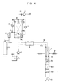
- Fig.4 illustrates an entire system for soil stabilization.
- the injection tube 1 is an injection tube which is inserted into the earth E and set there for impregnating grout G into an ambient portion of the ground.
- the injection tube 1 is used in combination with grout supplying system consisting essentially of a carbon dioxide gas CO2 source, e.g. a carbon dioxide gas bomb 2, a packed absorber 3, a water source 4, a water-glass tank 5 and a grouting pump 6.
- Carbon dioxide gas CO2 form the gas bomb 2 is supplied to the absorber 3, preferably to a lower portion of the absorber 3 through a vaporizer 7 for enhancing vaporization especially in a winter season and a gas flow control valve 8.
- the absorber 3 has packings 9 such as saddles or Raschig rings packed therein.
- the absorber 3 further includes a spray nozzle 10 installed at an upper portion thereof for spraying water 4 fed by a pump 11 through a flow control valve 12.
- the carbon dioxide gas and water are brought into contact with each other in the absorber 3 to produce carbonated water.
- the packings 9 enhance the gas-liquid contact.
- the carbonated water thus produced is drawn out from the bottom of the absorber 3 by the double acting pump 6 to be led, for example, into an inner path of the injection tube 1.
- an upper-and a lower-limit level detector 13U, 13L are provided at a lower portion of the absorber 3 in the present embodiment to control the water flow rate by operating the water flow control valve 12 by an liquid level controller 14 so that the liquid level of the carbonated water is kept between the upper- and lower-limit levels.
- the concentration of carbon dioxide dissolved in the carbonated water is also to be controlled because it influences the reactivity of the carbonated water with water glass.
- a pressure detector 15 is provided within the absorber 3. The gas flow is controlled by operating the gas flow control valve 8 by a pressure controller 16 to control the carbonated water concentration.
- water glass is drawn up from the tank 5 by a liquid feeding pump 17 and then led, for example, into an outer path of the injection tube 1.
- the carbonated water CW and the water glass NS are fed to a tip tube member of the injection tube as illustrated in Fig.1 through a swivel joint (not shown) and a coupling barrel of a known double-tube structure.
- the tip tube member comprises outer pipe elements 20A to 20E within which various members as will be described below are provided.
- a leading member 20, an intermediate member 31, a connecting member 32 and a trailing member 33 are threadedly engaged with each other and installed inside the tip tube member.
- the carbonated water CW first enters a first path a1 formed at a center of the leading member 30, passing through a plurality of second paths a2 formed so as to extend from a tip end of the first path a1 slantingly in a radial direction, through a third path a3 defined by a gap between the outer periphery of the leading member 30 and the inner surface of the outer pipe element 20A, and through a fourth path a4 formed so as to extend from a tip end of the third path a3 slantingly to a center of the outer pipe element 20A.
- the carbonated water CW is then led into a fifth path a5 formed at a central portion of the intermediate member 31 and further led to a sixth path a6 formed inside the trailing member 33, while pushing down a first dwelling or pressure-reducer valve 41 which is biased by a spring 34 resting against the trailing member 33.
- the water glass NS is introduced into a first path b1 formed by a gap between the outer periphery of the leading member 30 and the outer pipe element 20A and is forced to pass through a plurality of second paths b2 formed in the leading member 30 to extend along the axis thereof to reach a third path b3 formed centrally at the tip end portion of the leading member 30.
- the water glass then passes through a fourth path b4 within the intermediate member 31 while pushing down a check valve 43 urged by a spring 35 rested against the intermediate member 31 and passes through a plurality of fifth paths b5 formed within an increased diameter portion of the intermediate member 31 to extend along the axis thereof to reach a sixth path b6 formed by a gap between the outer peripheries of the intermediate member 31, the connecting member 32 and the trailing member 33 and the inner surfaces of the outer pipe elements 20A and 20B.
- 36 is a lock nut for locking the trailing member 33 relative to the intermediate member 32 after the force of the spring 34 is set by screwing the trailing member 33 to set an actuation pressure of the first pressure-reducer valve 41.
- 37 is a guide for the spring 35.
- a tip end portion of the trailing member 33 receives a mixing accelerator 50 fitted therein.
- a valve seat 61 for a second dwelling or pressure-holding valve 42 is disposed next to the tip end of the mixing accelerator 50.
- the second pressure-holding valve 42 is biased towards the valve seat 61 by a spring 64 resting against a seat 63 which is locked relative to the outer pipe element 20C by a lock nut 62.
- the mixing accelerator 50 is fitted closely within the outer pipe element 20B.
- the mixing accelerator 50 is formed in a columnar shape and is, for example, about 25cm in length.
- the mixing accelerator 50 has a groove on the outer periphery thereof.
- the groove comprises one or more reciprocating flow paths 51, five in the present embodiment.
- Each of the reciprocating paths is formed of a forward path section directed from a base to a tip and a backward path section returning to the base which communicate with each other.
- the groove further comprises an extra forward path for finally directing towards the tip end of the injection tube. Therefore, the materials flow along the groove of about 275cm (25 x 5 x 2 +25) in total.
- the mixing accelerating path has a length of 0.5m or more, preferably 1m or more.
- the path system a1 to a6 for the carbonated water CW and the path system b1 to b6 for the water glass NS are separate from each other before the tip end of the trailing member 33.
- the carbonated water CW and the water glass NS first meet when they enter the mix accelerating path 51 through an entrance recess 52A at a base end of the mixing accelerator 50 after they have passed the tip end of the trailing member 33. These materials thereafter are mixed sufficiently while being subjected to reaction for a sufficient time during their course of flowing through the long mix accelerating path 51.
- the resultant mixed up grout leaves the mix accelerating path 51 through an exit 52B and enters within the valve seat 61, then passing through grout paths g1 to g5 therein to be injected into the earth E through an injecting opening 70 at the tip end of the injection tube 1.
- the mixing accelerator 50 having the reciprocating paths can provide a desired length of mixing and reacting time prolonged as compared with that of the length of the mixing accelerator 50.
- the materials, the carbonated water and the glass water can be mixed sufficiently and it can be avoided that the materials are impregnated as they are separate.
- Ordinary two-part curable grouts other than that specified herein may be used after simple mixing of the two parts.
- carbonated water is not easily mixed up with water glass.
- the mixing acceleration arrangement employed in the present embodiment is very effective for the grout consisting of carbonated water and water glass.
- a mixing section for example 1kg/cm2 G or higher, preferably 3kg/cm2G or higher, more preferably 5kg/cm2G or higher.
- the first pressure-reducer valve 41 and the second pressure-holding valve 42 are provided before and after the mixing accelerator 50 in this embodiment. More specifically, to keep the mix accelerating path 51 at a relatively high pres-sure, carbonated water is supplied to the first pressure-redu-cer valve 41 under a pressure of 0.49 x 10⁶ N/m2 (5 kg/cm2G) or higher, preferably 0.98 x 10⁶ N/m2 (10 kg/cm2G) or higher, more preferably between 1.47 x 10⁶ N/m2 (15 kg/cm2G) and 3.92 x 10⁶ N/m2 (40 kg/cm2G).
- the actuating pressure of the second pressure holding-holding valve 42 is set to be 9,8 x 10⁴ N/m2 (1 kg/cm2G) or higher, preferably 0.29 x 10⁶ N/m2 (3 kg/cm2G) or higher, more preferably 0.49 x 10⁶ N/m2 (5 kg/cm2G) or higher.
- the pressure within the mixing section is kept at a pressure corresponding to the actuating pressure of the second pressure-holding valve 42.
- the check valve 43 is set so that it may operate when the dynamic pressure of the water glass acts on the valve.
- the pressure for supplying the water glass is 0.147 to 0.98 x 10⁶ N/m2 (1.5 - 10 kg/cm2G), preferably 0.29 to 0.68 x 10⁶ N/m2 (3 - 7 kg/cm2G).
- a check valve operates when a dynamic pressure is applied, whereas in this embodiment, the pressure reducer valve 41 and the pressure holding valve 42 are provided to keep the mix accelerating section between the valves 41, 42 at a desired high pressure, which is novel in the grout impregnation method.
- the mixing accelerator 50 in the present embodiment may be replaced by a mixing accelerator 50' having a helical mix accelerating path 51' (Fig. 5).
- the helical path consists of two helical path segments disposed alternatingly. These helical path segments communicate each other at a turning point 53' and one is directed to a tip end and another returns to a base. The returning path segment further communicates at the base end thereof with a center path 54' which opens at a tip end 55 thereof.
- the water glass and the carbonated water may alternatively be brought into contact with each other at a position upstream of the mixing accelarator 50 as illustrated in Fig. 6.
- the water glass NS passes through a seventh path b7 formed in a wall of the connecting member 32 and is brought into contact with the carbonated water CW at a position adjacent to and downstream than the first pressure reducer valve 41.
- a plurality of mix accelerators may be combined in axial direction of the tube.
- the injecting opening 70 may be set back from the tip end face of the injection tube 1.
- the injection tube may have a triple-flow path structure. In this case, two flow paths may be used for grout feeding and one flow path is used for water feeding at a time of boring.
- first pressure reducer valve and the second pressure-holding valve and the mixing section are provided within the injection tube, it may alternatively be provided outside of the tube as illustrated in Fig. 7.
- water glass NS is supplied from a pump through a hose, enters a mixing chamber 102 provided at an intersection, while pushing down a check valve 101.
- carbonated water CW supplied from a pump through a hose pushes down a ceck valve 103 and then passes through a space between a conical portion of a first pressure-reducer valve 104 and a valve seat 105 to enter the mixing chamber 102, where the carbonated water is brought into contact with the water glass and mixed therewith.
- an adjusting handle 106 may be operated to change a gap between the conical portion of the first pressure reducer valve 104 and the valve seat 105 to maintain the pressure determined by the first pressure reducer valve.
- a reacting chamber 108 having a long pipe path 107 is connected to the mixing chamber 102. The materials are allowed to react sufficiently when they flow through the reacting chamber 108.
- a second pressure-holding valve 109 is provided downstream of the reacting chamber 108. The grout passes through the second pressure-holding valve 109 and is fed to a supplying hose 111 through an exit 110 and supplied to an injection tube 1A.
- An actuating pressure of the second pressure-holding valve 109 is adjustable by a control handle 112.
- Fig.8 illustrate another form of a pressure-holding valve system which is identical with that of Fig.7 except that a first pressure-reducer valve 104A is urged by a spring 113, the force of which is controllable by the control handle 106. In this case, a seat 104B for the spring 113 is displaced.
- Fig.9 illustrate a still another form of a pressure-holding valve system in which a first pressure-reducer valve 115 and a check valve 116 are provided within a T-shaped casing 114.
- Carbonated water CW passes through a through hole 115a of the first pressure-reducer valve 115 and pushes down the first pressure-reducer valve 115 against the action of the spring 117.
- the carbonated water CW then passes through a long, narrow flow path 118 to reach a mingling chamber 119.
- the water glass NS passes through a through hole 116a to push down a check valve 116 and is then combined with the carbonated water CW at the mingling chamber 119.
- the mixed materials are then guided through a mix accelerating path (not shown) to reach a second pressure-holding valve (not shown).
Landscapes
- Engineering & Computer Science (AREA)
- Structural Engineering (AREA)
- Life Sciences & Earth Sciences (AREA)
- General Life Sciences & Earth Sciences (AREA)
- Soil Sciences (AREA)
- Environmental & Geological Engineering (AREA)
- Agronomy & Crop Science (AREA)
- Mining & Mineral Resources (AREA)
- Paleontology (AREA)
- Civil Engineering (AREA)
- General Engineering & Computer Science (AREA)
- Consolidation Of Soil By Introduction Of Solidifying Substances Into Soil (AREA)
- Soil Conditioners And Soil-Stabilizing Materials (AREA)
Description
- The invention relates to a grout impregnation method which uses an injection tube for contacting and mixing different kinds of materials supplied separately thereinto to prepare a grout and impregnates the grout into the earth through an injector opening provided at a tip end of the tube.
- In the past, a single-liquid grout was used for impregnation. This conventional grout impregnation method was improved in various ways: For example, by using two liquids which cure when reacted with each other (two part curable grout). In this process, the said two liquids are mingled in a Y-shaped pipe provided at a base portion of an injection tube. In a further improvement of this method, the two liquids are mingled and mixed within the injection pipe and the resultant grout is injected into the earth.
- US-A-3,878,686 further describes a grouting process for filling subterranean voids by controlled feeding and mixing foam-forming ingredients, such as isocyanates and polyols, and an expanding agent, such as compressed or liquified fluoro carbon gases, to pre-expand the foam-forming ingredients in the vicinity of the void and form a fluid, closed cell, froth foam material, and then discharging the fluid foam material into the void to fill the void before the foam material gels.
- Although various kinds of two-part curable grouts are known, today, a grout with water glass (sodium silicate) is most widely used because it does not pollute the soil. GB-A-2,063,337 describes e.g. such a grouting process. The sodium silicate grout is prepared therein by separately introducing, under elevated pressure, an aqueous sodium silicate solution and gaseous carbon dioxide into a double piping system from its inlet. Said double piping system has a line mixer in the pipe near the outlet and at the outlet a check valve. The mechanism is such, that the valve hole opens when the inner pressure of the pipe exceeds an appointed pressure but the valve keeps closed so long as the inner pressure of the pipe is not higher than the appointed pressure, followed by mixing them together in the pipe, discharging the resulting mixture from the outlet and injecting it into ground to fill the subterranean voids.
- Water glass may be used alternatively with a reactant such as an acid or a salt of an acid to provide a grout to be impregnated into the earth for stabilization of the soil. Water glass may be used for example with carbonated water as disclosed for example in Japanese Kokai 53-74709.
- Carbon dioxide has the advantage that it is harmless and not expensive. However, there is a problem to prepare carbonated water by absorbing carbon dioxide in water and to use the resultant carbonated water with water glass as a grout. The solution to this will be described later. By this reason, this grout has not been put into practical use heretofore.
Such a reaction is given by:
2H⁺ + CO₃²⁻ + Na₂O nSiO₂ → Na₂CO₃ + H₂O + nSiO₂
- Thus, when carbonated water and water glass are impregnated into the soil after their mixing, silica and sodium carbonate are produced in the soil to solidify flimsy portions of the earth, stabilizing the same.
- In the conventional grout impregnation using a two-part curable grout, it has been considered essential to mix the two liquids supplied in equal amounts under equal pressures. The conventional grout impregnation of this type, in effect, is carried out by mixing the two liquid-parts of equal amounts under equal pressures.
- However, when the carbonated water is prepared at first and then supplied to the injection pipe, the carbonated water is liable to separation into water and carbon dioxide gas, if the pressure within the pipe is not high enough, and cannot react with water glass sufficiently. On the other hand, when it is necessary to prepare the carbonated water at the execution site, the water and the carbon dioxide gas have to be contacted under a high pressure in a closed vessel to obtain carbonated water of high concentration. By this reason, carbonated water should inevitably be led to the injection tube under a high pressure. In addition, the pressure within the dissolving vessel for preparing carbonated water should be increased to shorten the gelling time of the grout as shown in Fig. 10.
- If carbonated water is thus supplied into the injection pipe under a high pressure and water glass is supplied thereinto under a low pressure, the flow of carbonated water become dominant within the pipe and the two liquids are not reacted sufficiently.
- A valve provided after the mixing of the two liquids has been known. However, the known valve after the mixing of the liquids is a check valve for preventing back flow of soil into the injection pipe after injection of the grout into the soil, and not a valve for holding the pressure in the mixing section. A valve is not provided, in the conventional technique, upstream the mixing section.
- It is therefore an object of the present invention to provide a grout impregnation method which allows the components of a curable grout to contact, mix and react with each other sufficiently and positively to prepare the grout which is capable of developing sufficient strength. It is further an object of the present invention to provide a grout impregnation method which enables sufficient mixing of the carbonated water which is supplied under a higher pressure than the water glass.
- The problem is solved by a grout impregnation method which uses an injection pipe for contacting and mixing different kinds of materials supplied separately thereinto to prepare a grout and impregnates the grout into the earth (E) through an injector opening provided at a tip end of the tube, with the following combination of steps:
providing a first pressure reducer valve within a higher-pressure path for carbonated water which is supplied under a higher pressure and passing said carbonated water through said first pressure reducer valve which reduces the pressure of said carbonated water;
providing a mixing section downstream said first pressure reducer valve but in the vicinity thereof and contacting and mixing said carbonated water after passing the first pressure reducer valve with water glass which is supplied under a lower pressure;
providing a second pressure holding valve downstream the mixing section, so that said contacting and mixing is carried out under a pressure determined by the second pressure holding valve and which exceeds the atmospheric pressure; and
impregnating the resulting grout into earth by passing it through the second pressure holding valve and the injector opening. - The present inventors have conducted various laboratory tests and pilot tests to achieve a grout impregnation method using water glass and carbonated water and found that there are some problems to be solved. Among these is a problem that carbonated water and water glass are impregnated into the earth possibly without being reacted sufficiently, deteriorating the soil stabilizing effect, if they are kept at a high pressure and subjected to a reaction for a sufficient time. More particularly, unless the material liquids are mixed and reacted sufficiently, carbonated water and water glass are separately injected into the earth. Moreover, carbonated water is further separated into water and CO₂ gas. It has been observed that a desired grout is not obtained when the mixing and rection are not sufficient and that CO₂ gas bubbles up from the injecting opening of the tube.
- This phenomenon can be explained as follows: when carbonated water is supplied under a high pressure and water glass is supplied under a lower pressure, if appropriate valve means are not provided for controlling the pressures and flow rates, carbonated water of a higher pressure becomes predominant in the flow and carbonated water is sprouted from the injecting opening of the tube without being sufficiently contacted, mixed and reacted with water glass. Carbonated water is further separated into carbon dioxide gas and water and carbon dioxide gas spurts out.
- With the first pressure-reducer valve provided within the path for the higher pressure material leading to the mixing section according to the present invention, the pressure after the first pressure-reducer valve is kept lower than the actuation pressure of the valve. At this lowered, subststantially equalized pressure, the material is made to contact and mix with the material which has been supplied under a lower pressure at the same supplying rate. As a result of this, the materials can be mixed with each other sufficiently and uniformly.
- With the second pressure-holding valve provided between the mixing section and the injecting opening of the tube, the mixing section is held at a pressure substantially the same as the actuation pressure of the second pressure-holding valve. If the second pressure-holding valve is not provided, the pressure of the mixing section is substantially atmospheric. Under this condition, the materials of the grout can not be mixed well. Whereas, if the pressure of the mixing section is kept at 9,8 x 10⁴ N/m² (1 kg/cm² x G) or higher, preferably 0,29 x 10⁶ N/m² (3 kg/cm² x G) or higher, more preferably 0,49 x 10⁶ N/m² (5 kg/cm² x G) or higher, the materials are contacted and mixed with each other in the mixing section at a high pressure and they are mixed uniformly.
- To obtain carbonated water of high concentration or a grout of shortend gelling time, the operating pressure within the dissolving vessel (packed absorber) for the preparation of carbonated water should be high as described above. For this reason, it may be possible to provide means for keeping the pressure within the packed absorber high and to provide a pressure reducing valve in a path for carbonated water leading to the injection tube. The mixing section is provided far downstream of the reducing valve for letting carbonated water contact with water glass. In this case, even if carbonated water and water glass are supplied and mixed under equal pressures, it is not possible to obtain a uniform, homogeneous grout.
- In contrast, it has been found that if the mixing section is provided within 2m, preferably within 1m, more preferably within 0.5m from the first pressure-reducer valve, the desired mixing of the materials can be attained. The reason of this in not known, but it may be inferred that the pressure of the carbonated water is rapidly reduced when carbonated water passes through the first pressure-reducer valve and it is diffused into the flow of water glass.
- The inventors have also found that mere contact of the two materials, carbonated water and water glass, is not sufficient to achieve sufficient reaction between them. In this case, carbonated water and water glass are impregnated into the earth separately. Whereas, if the liquids are kept to dwell, for a sufficiently long time, within a space limited by and between the first pressure-holding valve and the second pressure-holding valve, sufficient reaction between the materials is attained. To improve the contact and mixing, the contacting and mixing zone may be prolonged. However, the injection tube is formed, in use, by coupling a plurality of tube members into a desired length. Therefore, the length of the tip tube member of the injection tube is limited and can not be lengthened as desired.
- In a preferred embodiment of the present invention, a mixing accelerating section may be provided within the injection tube. In the mixing accelerating section, carbonated water and water glass flow a path consisting of at least one reciprocating path segment which is first directed towards the tip and then turns towards the base. Thus, an elongated or extended path length can be attained in a limited length of the tip tube member. As a result of this, sufficient reaction time can be obtained without elongating the tip tube member. This is also advantageous in maintenance and cleaning of the tube.
- Before this invention, there has not been known an idea of reciprocating flow of the material mixture in an axial direction of the tube.
- The present invention is suitably applied when the supplying pressures of the two materials of the two-part curable grout are different, especially when the ratio in supplying pressure of the higher-pressure liquid to the lower-pressure liquid is 1.2 or higher.
- The actuation pressure of the first pressure-holding valve is preferably 0.5 times or more and 1.5 times or less the supplying pressure of the liquid passing through the valve. If the ratio is less than 0.5, the higher-pressure liquid passing through the first pressure-holding valve becomes too predominant over the lower-pressure liquid to be mixed with the latter uniformly.
- When the desired grout comprises equal parts of two materials, the supplying rates of the liquids should be substantially equal. The ratio in supplying rate between the higher-pressure material and the lower-pressure material is preferably 0.7 to 1.3, more preferably 0.85 to 1.15 to attain uniform and homogeneous mixture. Of course, the grout may comprise different parts of the material and the supplying amounts may be out of the range as specified above.
- When the grout used has a shortened gelling time, it is preferred to provide the first pressure-reducer valve, the mixing section and the second pressure-holding valve in the tip tube member of the injection tube to prevent clogging of the flow path of the grout due to curing of the grout. However, if a grout of longer gelling time is used, the valves and the mixing section may be provided at more upstream portions of the tube because there is no fear of clogging due to the curing of the grout.
- The pressure-holding or pressure-reducer valve employable in the present invention may be valves biased by springs, or needle valves, or may be orifices. In other words, any kind of means may be employable as far as it operates to hold the pressure of the supplying line of the higher-pressure material, as the first pressure-holding valve or to keep the pressure within the mixing section or function as a check valve, as the second pressure-holding valve. Thus, the wording "valve" used herein should be interpreted widely.
-
- Fig.1 is a half-sectional view of one form of a tip tube member of an injection tube according to the present invention;
- Fig.2 is a half-sectional view of a principal portion of the injection tube shown in Fig.1;
- Fig.3 is a front view of a mixing accelerator employable in the present invention;
- Fig.4 is a block diagram showing an entire system for grout impregnation;
- Fig.5 is a perspective view of another form of mixing accelerator;
- Fig.6 is a half-sectional view of another form of a tip tube member of an injection tube employable in the present invention;
- Figs.7, 8 and 9 are sectional views of other forms of pressure-holding valve; and
- Fig.10 is a diagram showing a relationship between a pressure within a dissolving vessel during the preparation of carbonated water and a gelling time of the resultant grout.
- The invention will now be described referring to the drawings.
- Fig.4 illustrates an entire system for soil stabilization.
- 1 is an injection tube which is inserted into the earth E and set there for impregnating grout G into an ambient portion of the ground. The injection tube 1 is used in combination with grout supplying system consisting essentially of a carbon dioxide gas CO₂ source, e.g. a carbon dioxide gas bomb 2, a packed
absorber 3, a water source 4, a water-glass tank 5 and agrouting pump 6. Carbon dioxide gas CO₂ form the gas bomb 2 is supplied to theabsorber 3, preferably to a lower portion of theabsorber 3 through a vaporizer 7 for enhancing vaporization especially in a winter season and a gas flow control valve 8. Theabsorber 3 haspackings 9 such as saddles or Raschig rings packed therein. Theabsorber 3 further includes aspray nozzle 10 installed at an upper portion thereof for spraying water 4 fed by apump 11 through aflow control valve 12. - Thus, the carbon dioxide gas and water are brought into contact with each other in the
absorber 3 to produce carbonated water. At this time, thepackings 9 enhance the gas-liquid contact. The carbonated water thus produced is drawn out from the bottom of theabsorber 3 by thedouble acting pump 6 to be led, for example, into an inner path of the injection tube 1. - It is very crucial to balance the production of the carbonated water with the feed (or consumption) of the carbonated water by the
pump 6. By this reason, an upper-and a lower-limit level detector absorber 3 in the present embodiment to control the water flow rate by operating the waterflow control valve 12 by anliquid level controller 14 so that the liquid level of the carbonated water is kept between the upper- and lower-limit levels. In addition to the liquid level control, the concentration of carbon dioxide dissolved in the carbonated water is also to be controlled because it influences the reactivity of the carbonated water with water glass. To this end, apressure detector 15 is provided within theabsorber 3. The gas flow is controlled by operating the gas flow control valve 8 by apressure controller 16 to control the carbonated water concentration. - On the other hand, water glass is drawn up from the
tank 5 by aliquid feeding pump 17 and then led, for example, into an outer path of the injection tube 1. - Referring further to Figs.1 to 3, the carbonated water CW and the water glass NS are fed to a tip tube member of the injection tube as illustrated in Fig.1 through a swivel joint (not shown) and a coupling barrel of a known double-tube structure.
- The tip tube member comprises
outer pipe elements 20A to 20E within which various members as will be described below are provided. - At a base end portion of the tip tube member, a leading
member 20, anintermediate member 31, a connectingmember 32 and a trailingmember 33 are threadedly engaged with each other and installed inside the tip tube member. The carbonated water CW first enters a first path a1 formed at a center of the leadingmember 30, passing through a plurality of second paths a2 formed so as to extend from a tip end of the first path a1 slantingly in a radial direction, through a third path a3 defined by a gap between the outer periphery of the leadingmember 30 and the inner surface of theouter pipe element 20A, and through a fourth path a4 formed so as to extend from a tip end of the third path a3 slantingly to a center of theouter pipe element 20A. The carbonated water CW is then led into a fifth path a5 formed at a central portion of theintermediate member 31 and further led to a sixth path a6 formed inside the trailingmember 33, while pushing down a first dwelling or pressure-reducer valve 41 which is biased by aspring 34 resting against the trailingmember 33. - The water glass NS is introduced into a first path b1 formed by a gap between the outer periphery of the leading
member 30 and theouter pipe element 20A and is forced to pass through a plurality of second paths b2 formed in the leadingmember 30 to extend along the axis thereof to reach a third path b3 formed centrally at the tip end portion of the leadingmember 30. The water glass then passes through a fourth path b4 within theintermediate member 31 while pushing down acheck valve 43 urged by aspring 35 rested against theintermediate member 31 and passes through a plurality of fifth paths b5 formed within an increased diameter portion of theintermediate member 31 to extend along the axis thereof to reach a sixth path b6 formed by a gap between the outer peripheries of theintermediate member 31, the connectingmember 32 and the trailingmember 33 and the inner surfaces of theouter pipe elements - 36 is a lock nut for locking the trailing
member 33 relative to theintermediate member 32 after the force of thespring 34 is set by screwing the trailingmember 33 to set an actuation pressure of the first pressure-reducer valve 41. 37 is a guide for thespring 35. - A tip end portion of the trailing
member 33 receives a mixingaccelerator 50 fitted therein. Avalve seat 61 for a second dwelling or pressure-holdingvalve 42 is disposed next to the tip end of the mixingaccelerator 50. The second pressure-holdingvalve 42 is biased towards thevalve seat 61 by aspring 64 resting against aseat 63 which is locked relative to theouter pipe element 20C by alock nut 62. - The mixing
accelerator 50 is fitted closely within theouter pipe element 20B. The mixingaccelerator 50 is formed in a columnar shape and is, for example, about 25cm in length. The mixingaccelerator 50 has a groove on the outer periphery thereof. The groove comprises one or morereciprocating flow paths 51, five in the present embodiment. Each of the reciprocating paths is formed of a forward path section directed from a base to a tip and a backward path section returning to the base which communicate with each other. The groove further comprises an extra forward path for finally directing towards the tip end of the injection tube. Therefore, the materials flow along the groove of about 275cm (25 x 5 x 2 +25) in total. In general, the mixing accelerating path has a length of 0.5m or more, preferably 1m or more. - As can be understood from the foregoing description, the path system a1 to a6 for the carbonated water CW and the path system b1 to b6 for the water glass NS are separate from each other before the tip end of the trailing
member 33. The carbonated water CW and the water glass NS first meet when they enter themix accelerating path 51 through anentrance recess 52A at a base end of the mixingaccelerator 50 after they have passed the tip end of the trailingmember 33. These materials thereafter are mixed sufficiently while being subjected to reaction for a sufficient time during their course of flowing through the longmix accelerating path 51. The resultant mixed up grout leaves themix accelerating path 51 through anexit 52B and enters within thevalve seat 61, then passing through grout paths g1 to g5 therein to be injected into the earth E through an injectingopening 70 at the tip end of the injection tube 1. - In this connection, it is to be noted that only two reciprocating paths and one extra forwarding path are shown in section of the mixing
accelerator 50 in Figs.1 and 2 to simplify the illustration. - As described above, the mixing
accelerator 50 having the reciprocating paths can provide a desired length of mixing and reacting time prolonged as compared with that of the length of the mixingaccelerator 50. Thus, the materials, the carbonated water and the glass water, can be mixed sufficiently and it can be avoided that the materials are impregnated as they are separate. Ordinary two-part curable grouts other than that specified herein may be used after simple mixing of the two parts. However, carbonated water is not easily mixed up with water glass. By this reason, the mixing acceleration arrangement employed in the present embodiment is very effective for the grout consisting of carbonated water and water glass. - To handle carbonated water and water glass which are difficult to mix, it is desirable, as well as to prolong the reaction time, to mix them under a relatively high pressure within a mixing section (chamber), for example 1kg/cm² G or higher, preferably 3kg/cm²G or higher, more preferably 5kg/cm²G or higher.
- To this end, the first pressure-
reducer valve 41 and the second pressure-holdingvalve 42 are provided before and after the mixingaccelerator 50 in this embodiment. More specifically, to keep themix accelerating path 51 at a relatively high pres-sure, carbonated water is supplied to the first pressure-redu-cer valve 41 under a pressure of 0.49 x 10⁶ N/m² (5 kg/cm²G) or higher, preferably 0.98 x 10⁶ N/m² (10 kg/cm²G) or higher, more preferably between 1.47 x 10⁶ N/m² (15 kg/cm²G) and 3.92 x 10⁶ N/m² (40 kg/cm²G). In addition, the actuating pressure of the second pressure holding-holdingvalve 42 is set to be 9,8 x 10⁴ N/m² (1 kg/cm²G) or higher, preferably 0.29 x 10⁶ N/m² (3 kg/cm²G) or higher, more preferably 0.49 x 10⁶ N/m² (5 kg/cm²G) or higher. With this arrangement, the pressure within the mixing section is kept at a pressure corresponding to the actuating pressure of the second pressure-holdingvalve 42. With respect to water glass NS, thecheck valve 43 is set so that it may operate when the dynamic pressure of the water glass acts on the valve. The pressure for supplying the water glass is 0.147 to 0.98 x 10⁶ N/m² (1.5 - 10 kg/cm²G), preferably 0.29 to 0.68 x 10⁶ N/m² (3 - 7 kg/cm²G). - In a conventional injection tube, a check valve operates when a dynamic pressure is applied, whereas in this embodiment, the
pressure reducer valve 41 and thepressure holding valve 42 are provided to keep the mix accelerating section between thevalves - The mixing
accelerator 50 in the present embodiment may be replaced by a mixing accelerator 50' having a helical mix accelerating path 51' (Fig. 5). In this case, the helical path consists of two helical path segments disposed alternatingly. These helical path segments communicate each other at a turning point 53' and one is directed to a tip end and another returns to a base. The returning path segment further communicates at the base end thereof with a center path 54' which opens at atip end 55 thereof. - The water glass and the carbonated water may alternatively be brought into contact with each other at a position upstream of the mixing
accelarator 50 as illustrated in Fig. 6. In this case, the water glass NS passes through a seventh path b7 formed in a wall of the connectingmember 32 and is brought into contact with the carbonated water CW at a position adjacent to and downstream than the firstpressure reducer valve 41. - In this connection, it is to be noted that a plurality of mix accelerators may be combined in axial direction of the tube. The injecting
opening 70 may be set back from the tip end face of the injection tube 1. The injection tube may have a triple-flow path structure. In this case, two flow paths may be used for grout feeding and one flow path is used for water feeding at a time of boring. - Although the first pressure reducer valve and the second pressure-holding valve and the mixing section are provided within the injection tube, it may alternatively be provided outside of the tube as illustrated in Fig. 7. In Fig. 7, water glass NS is supplied from a pump through a hose, enters a mixing
chamber 102 provided at an intersection, while pushing down acheck valve 101. On the other hand, carbonated water CW supplied from a pump through a hose pushes down aceck valve 103 and then passes through a space between a conical portion of a first pressure-reducer valve 104 and avalve seat 105 to enter the mixingchamber 102, where the carbonated water is brought into contact with the water glass and mixed therewith. When the pressure for supplying the carbonated water is changed, an adjustinghandle 106 may be operated to change a gap between the conical portion of the firstpressure reducer valve 104 and thevalve seat 105 to maintain the pressure determined by the first pressure reducer valve. A reactingchamber 108 having along pipe path 107 is connected to the mixingchamber 102. The materials are allowed to react sufficiently when they flow through the reactingchamber 108. A second pressure-holdingvalve 109 is provided downstream of the reactingchamber 108. The grout passes through the second pressure-holdingvalve 109 and is fed to a supplyinghose 111 through anexit 110 and supplied to aninjection tube 1A. An actuating pressure of the second pressure-holdingvalve 109 is adjustable by acontrol handle 112. - Fig.8 illustrate another form of a pressure-holding valve system which is identical with that of Fig.7 except that a first pressure-
reducer valve 104A is urged by aspring 113, the force of which is controllable by thecontrol handle 106. In this case, aseat 104B for thespring 113 is displaced. - Fig.9 illustrate a still another form of a pressure-holding valve system in which a first pressure-
reducer valve 115 and acheck valve 116 are provided within a T-shapedcasing 114. Carbonated water CW passes through a throughhole 115a of the first pressure-reducer valve 115 and pushes down the first pressure-reducer valve 115 against the action of thespring 117. The carbonated water CW then passes through a long,narrow flow path 118 to reach amingling chamber 119. The water glass NS passes through a throughhole 116a to push down acheck valve 116 and is then combined with the carbonated water CW at the minglingchamber 119. The mixed materials are then guided through a mix accelerating path (not shown) to reach a second pressure-holding valve (not shown).
Claims (9)
- Grout impregnation method which uses an injection tube (1) for contacting and mixing different kinds of materials supplied separately thereinto to prepare a grout and impregnates the grout into the earth (E) through an injector opening (70) provided at a tip end of the tube (1), characterized by the following combination of steps:
providing a first pressure reducer valve (41) within a higher-pressure path (al - a6) for carbonated water (CW) which is supplied under a higher pressure and passing said carbonated water through said first pressure reducer valve (41) which reduces the pressure of said carbonated water;
providing a mixing section (50) downstream said first pressure reducer valve (41) but in the vicinity thereof and contacting and mixing said carbonated water after passing the first pressure reducer valve (41) with water glass (NS) which is supplied under a lower pressure;
providing a second pressure holding valve (42) downstream the mixing section (50), so that said contacting and mixing is carried out under a pressure determined by the second pressure holding valve (42) and which exceeds the atmospheric pressure; and
impregnating the resulting grout into earth by passing it through the second pressure holding valve (42) and the injector opening (70). - A grout impregnation method according to claim 1, characterized in that said first pressure reducer valve (41), said mixing section (50) and said second pressure holding valve (42) are provided within the injection tube.
- A grout impregnation method according to claim 1, characterized in that said first pressure reducer valve (41), said mixing section (50) and said second pressure holding valve (42) are provided outside of the injection tube:
- A grout impregnation method according to anyone of the preceding claims 1 - 3, characterized in that the feeding pressure of the carbonated water to be passed through said first pressure reducer valve (41) is at least 1.2 times as high as that of the water glass.
- A grout impregnation method according to anyone of the preceding claims 1 - 4, characterized in that the actuation pressure of the first pressure reducer valve (41) is in the range between 0.5 to 1.5 times the pressure of the supplied carbonated water passing through said valve (41).
- A grout impregnation method according to claim 1, characterized in that an actuation pressure of the second pressure holding valve (42) is 0,29 x 10⁶ N/m² or higher, whereby the pressure within the mixing section (50) is kept 0,29 x 10⁶ N/m² or higher.
- A grout impregnation method according to anyone of the preceding claims 1 - 6, characterized in that the actuation pressures of the first pressure reducer valve (41) and the second pressure-holding valve (42) are determined by springs (34, 64) each urging the valves towards the base end of the injection tube, respectively.
- A grout impregnation method according to anyone of the preceding claims 1 - 7, characterized in that the materials are brought into contact with each other in the mixing section (50) and the resultant mixture is forced to make at least one reciprocating flow directed towards the tip end of the injection tube and vice versa and finally led to be impregnated through the opening (70) of the tube into ambient earth.
- A grout impregnation method according to anyone of the preceding claims 1 - 8, characterized in, that a mixing accelerator (50') is fitted in the injection tube, which accelerator has at least one reciprocating path (51') which is directed towards the tip end of the tube and then vice versa, said reciprocating path (51') being communicated with the injecting opening (70) at the tip end of the injection tube.
Applications Claiming Priority (4)
| Application Number | Priority Date | Filing Date | Title |
|---|---|---|---|
| JP4705986 | 1986-03-04 | ||
| JP4705886 | 1986-03-04 | ||
| JP47058/86 | 1986-03-04 | ||
| JP47059/86 | 1986-03-04 |
Publications (3)
| Publication Number | Publication Date |
|---|---|
| EP0236560A2 EP0236560A2 (en) | 1987-09-16 |
| EP0236560A3 EP0236560A3 (en) | 1987-10-14 |
| EP0236560B1 true EP0236560B1 (en) | 1991-12-18 |
Family
ID=26387208
Family Applications (1)
| Application Number | Title | Priority Date | Filing Date |
|---|---|---|---|
| EP86116563A Expired - Lifetime EP0236560B1 (en) | 1986-03-04 | 1986-11-28 | Impregnation method of unfirm ground |
Country Status (5)
| Country | Link |
|---|---|
| US (1) | US4725169A (en) |
| EP (1) | EP0236560B1 (en) |
| JP (1) | JP2630587B2 (en) |
| KR (1) | KR910009254B1 (en) |
| CN (1) | CN87100030B (en) |
Families Citing this family (10)
| Publication number | Priority date | Publication date | Assignee | Title |
|---|---|---|---|---|
| JPS63255418A (en) * | 1987-04-10 | 1988-10-21 | Shohei Senda | Valve switch for chemical grout injector |
| US5342149A (en) * | 1992-08-31 | 1994-08-30 | Mccabe Brothers, Inc. | Long hole chemical grout injector system |
| KR100467863B1 (en) * | 2002-09-05 | 2005-01-26 | 주식회사 우정엔지니어링건축사사무소 | Direct-boring grouting apparatus |
| KR100488593B1 (en) * | 2002-10-17 | 2005-05-12 | (주)진양비지엠텍 | grouting apparatus |
| US6863475B2 (en) * | 2003-04-30 | 2005-03-08 | Shell Oil Company | Apparatus for injecting fluids |
| SE533769C2 (en) * | 2009-05-06 | 2010-12-28 | Malmfaelten Ab | Method, system, use of systems and reinforcing means in rock reinforcement |
| CN104452740B (en) * | 2014-11-21 | 2017-03-15 | 淮海工学院 | A kind of method of Reinforcement liquefaction sand foundation |
| KR102073606B1 (en) * | 2019-07-16 | 2020-02-07 | 류동성 | Grouting method using activated silicate |
| CN110514811A (en) * | 2019-08-29 | 2019-11-29 | 山东科技大学 | An indoor simulated grouting reinforcement test device and method |
| CN111021169B (en) * | 2019-09-04 | 2021-03-02 | 西南交通大学 | Railway track disaster repair detection embedded body and use method thereof |
Family Cites Families (15)
| Publication number | Priority date | Publication date | Assignee | Title |
|---|---|---|---|---|
| US3518834A (en) * | 1968-05-09 | 1970-07-07 | Soil Testing Services Inc | Grouting system |
| US3878686A (en) * | 1972-11-21 | 1975-04-22 | Geol Associates Inc | Grouting process |
| US3986536A (en) * | 1975-06-16 | 1976-10-19 | Sprague & Henwood, Inc. | Grout injecting apparatus |
| JPS5369408A (en) * | 1976-12-02 | 1978-06-20 | Nitto Chemical Industry Co Ltd | Method of stabilizing nature of soil |
| JPS5532849A (en) * | 1978-08-30 | 1980-03-07 | Sato Kogyo Kk | Grouting method |
| JPS5575017A (en) * | 1978-11-30 | 1980-06-06 | Shin Nippon Techno Kk | Method and apparatus for liquid chemical injection by boring |
| JPS5667391A (en) * | 1979-11-08 | 1981-06-06 | Nitto Chem Ind Co Ltd | Injection of silicate-based grout into ground |
| JPS5944454B2 (en) * | 1980-11-05 | 1984-10-30 | 佐藤工業株式会社 | Grout injection method |
| JPS57158284A (en) * | 1981-03-24 | 1982-09-30 | Nitto Chem Ind Co Ltd | Injection of silicate-based grout into ground |
| JPS5845739U (en) * | 1981-09-22 | 1983-03-28 | 久保田建設株式会社 | Two-liquid mixing injection gun |
| JPS58106013A (en) * | 1981-12-16 | 1983-06-24 | Nippon Soiru Kogyo Kk | Method and apparatus for grout injection work |
| JPS58141283A (en) * | 1982-02-16 | 1983-08-22 | Nitto Chem Ind Co Ltd | Ground injection method of silicate grout |
| JPS5862212A (en) * | 1982-04-05 | 1983-04-13 | Nippon Sogo Bosui Kk | Grout injector |
| JPS5953585A (en) * | 1982-09-20 | 1984-03-28 | Kyokado Eng Co Ltd | Grouting process |
| JPS60138113A (en) * | 1983-12-24 | 1985-07-22 | Hazama Gumi Ltd | Injection nozzle for cement mortar |
-
1986
- 1986-11-25 JP JP61280524A patent/JP2630587B2/en not_active Expired - Lifetime
- 1986-11-28 EP EP86116563A patent/EP0236560B1/en not_active Expired - Lifetime
- 1986-12-12 US US06/941,253 patent/US4725169A/en not_active Expired - Fee Related
- 1986-12-31 KR KR1019860011724A patent/KR910009254B1/en not_active Expired
-
1987
- 1987-01-06 CN CN87100030A patent/CN87100030B/en not_active Expired
Also Published As
| Publication number | Publication date |
|---|---|
| JP2630587B2 (en) | 1997-07-16 |
| US4725169A (en) | 1988-02-16 |
| CN87100030A (en) | 1987-09-16 |
| KR870009080A (en) | 1987-10-23 |
| JPS6311712A (en) | 1988-01-19 |
| EP0236560A2 (en) | 1987-09-16 |
| EP0236560A3 (en) | 1987-10-14 |
| KR910009254B1 (en) | 1991-11-07 |
| CN87100030B (en) | 1988-10-05 |
Similar Documents
| Publication | Publication Date | Title |
|---|---|---|
| US4725169A (en) | Grout impregnation method | |
| US5118197A (en) | Process for mixing two liquids | |
| US5895817A (en) | Method and apparatus for direct oxygen injection with a reactant stream into a fluidized bed reactor | |
| JPS6221928B2 (en) | ||
| JPS6381191A (en) | Production device for impregnating material for ground | |
| KR910009252B1 (en) | Manufacture of ground grouting material | |
| KR910009251B1 (en) | Ground impregnating process | |
| JPH0360968B2 (en) | ||
| US20150322228A1 (en) | Method and system for producing a binder foam for producing asphalt | |
| US5435668A (en) | Method for controlling a final pile diameter in a cast-in-place of solidification pile by a jet process | |
| JPH0128075B2 (en) | ||
| SU1180005A1 (en) | Method of obtaining froth for fighting fire | |
| JPH0757870B2 (en) | Method and apparatus for manufacturing ground injection chemicals | |
| JP2001311138A (en) | Injection device into ground and production method of ground injection chemical | |
| SU1321831A1 (en) | Bubbling foam generator | |
| JPH0565649B2 (en) | ||
| JPH02225591A (en) | Method and apparatus for producing grout and method for grouting | |
| SU1404637A1 (en) | Installation for making and injecting hardening gas-liquid mixture | |
| SU1257229A2 (en) | Device for production of inert foam | |
| JPH0931963A (en) | Soil improvement method | |
| JPS6241282A (en) | Ground injection method of silicate grout | |
| KR840000997B1 (en) | Ground Injection Device | |
| JP3598148B2 (en) | Ground improvement method | |
| JPH0474485B2 (en) | ||
| JPH0516499B2 (en) |
Legal Events
| Date | Code | Title | Description |
|---|---|---|---|
| PUAI | Public reference made under article 153(3) epc to a published international application that has entered the european phase |
Free format text: ORIGINAL CODE: 0009012 |
|
| PUAL | Search report despatched |
Free format text: ORIGINAL CODE: 0009013 |
|
| 17P | Request for examination filed |
Effective date: 19861216 |
|
| AK | Designated contracting states |
Kind code of ref document: A2 Designated state(s): AT BE CH DE ES FR GB GR IT LI LU NL SE |
|
| AK | Designated contracting states |
Kind code of ref document: A3 Designated state(s): AT BE CH DE ES FR GB GR IT LI LU NL SE |
|
| RBV | Designated contracting states (corrected) |
Designated state(s): FR GB IT |
|
| 17Q | First examination report despatched |
Effective date: 19890213 |
|
| GRAA | (expected) grant |
Free format text: ORIGINAL CODE: 0009210 |
|
| AK | Designated contracting states |
Kind code of ref document: B1 Designated state(s): FR GB IT |
|
| ITF | It: translation for a ep patent filed | ||
| ET | Fr: translation filed | ||
| PLBE | No opposition filed within time limit |
Free format text: ORIGINAL CODE: 0009261 |
|
| STAA | Information on the status of an ep patent application or granted ep patent |
Free format text: STATUS: NO OPPOSITION FILED WITHIN TIME LIMIT |
|
| 26N | No opposition filed | ||
| PGFP | Annual fee paid to national office [announced via postgrant information from national office to epo] |
Ref country code: GB Payment date: 19961108 Year of fee payment: 11 |
|
| PGFP | Annual fee paid to national office [announced via postgrant information from national office to epo] |
Ref country code: FR Payment date: 19961118 Year of fee payment: 11 |
|
| PG25 | Lapsed in a contracting state [announced via postgrant information from national office to epo] |
Ref country code: GB Free format text: LAPSE BECAUSE OF NON-PAYMENT OF DUE FEES Effective date: 19971128 |
|
| PG25 | Lapsed in a contracting state [announced via postgrant information from national office to epo] |
Ref country code: FR Free format text: THE PATENT HAS BEEN ANNULLED BY A DECISION OF A NATIONAL AUTHORITY Effective date: 19971130 |
|
| GBPC | Gb: european patent ceased through non-payment of renewal fee |
Effective date: 19971128 |
|
| REG | Reference to a national code |
Ref country code: FR Ref legal event code: ST |
|
| PG25 | Lapsed in a contracting state [announced via postgrant information from national office to epo] |
Ref country code: IT Free format text: LAPSE BECAUSE OF NON-PAYMENT OF DUE FEES;WARNING: LAPSES OF ITALIAN PATENTS WITH EFFECTIVE DATE BEFORE 2007 MAY HAVE OCCURRED AT ANY TIME BEFORE 2007. THE CORRECT EFFECTIVE DATE MAY BE DIFFERENT FROM THE ONE RECORDED. Effective date: 20051128 |