EP0236237B1 - Continuous casting machine for metal - Google Patents
Continuous casting machine for metal Download PDFInfo
- Publication number
- EP0236237B1 EP0236237B1 EP87400491A EP87400491A EP0236237B1 EP 0236237 B1 EP0236237 B1 EP 0236237B1 EP 87400491 A EP87400491 A EP 87400491A EP 87400491 A EP87400491 A EP 87400491A EP 0236237 B1 EP0236237 B1 EP 0236237B1
- Authority
- EP
- European Patent Office
- Prior art keywords
- frame
- guiding
- continuous casting
- ingot mould
- plant according
- Prior art date
- Legal status (The legal status is an assumption and is not a legal conclusion. Google has not performed a legal analysis and makes no representation as to the accuracy of the status listed.)
- Expired - Lifetime
Links
Images

Classifications
-
- B—PERFORMING OPERATIONS; TRANSPORTING
- B22—CASTING; POWDER METALLURGY
- B22D—CASTING OF METALS; CASTING OF OTHER SUBSTANCES BY THE SAME PROCESSES OR DEVICES
- B22D11/00—Continuous casting of metals, i.e. casting in indefinite lengths
- B22D11/04—Continuous casting of metals, i.e. casting in indefinite lengths into open-ended moulds
- B22D11/053—Means for oscillating the moulds
Definitions
- the subject of the invention is an installation for the continuous casting of metal and in particular steel according to the preamble of claim 1.
- Such installations have been known for a long time, which generally comprise, on a fixed support frame, an ingot mold and a secondary cooling device aligned along a casting axis.
- the mold consists of a set of walls cooled by circulation of fluid, delimiting a bottomless casting cavity and mounted on a frame in the form of a sufficiently rigid frame to precisely maintain the positioning of the walls, these possibly being moved to adjust the dimensions of the casting cavity.
- the secondary cooling device itself consists of a set of guide and cooling members, generally rollers or guide plates associated with water spray bars, the set being mounted on a chassis. support and thus delimiting a corridor placed in the extension of the mold along the casting axis and sometimes called "guide corset".
- the steel poured into the mold cavity forms, along the cooled walls thereof, a crust whose thickness increases downwards and which is evacuated by the opposite end of the cavity, the cast product, consisting of 'a liquid core enclosed in the solidified crust, then passing into the guide corset, the upper part of which is placed near the outlet of the mold.
- the cooling continues inside the guide corset which opens, at its lower part, into a product extraction member.
- the casting can be done vertically or else in a curved manner, the guide corset bringing the product poured vertically to the horizontal point.
- the mold is carried by support and guiding members allowing oscillations parallel to the casting axis and associated with an oscillation control means whose amplitude and frequency are adjustable as required.
- an oscillation control means whose amplitude and frequency are adjustable as required.
- the support and oscillation lever which normally has two branches placed on the side and d 'other of the mold, can be connected to the oscillation table by two rods articulated on one side on the table and the other on each of the two branches. But the two arms of the lever can also be articulated directly on the oscillation table, the latter being held by two other connecting rods directed in directions substantially parallel to the two arms of the lever, the exact orientation being determined so that the displacement of the mold is made along the casting axis.
- the lever and the connecting rods are articulated on bearings carried by parts forming support chairs placed and fixed on a fixed platform (FR-A 2 055 784).
- the lever is reciprocated by an oscillation control mechanism which, most often, is an eccentric mechanism mounted on the support frame at a point relatively distant from the mold, below the work floor .
- the forces due to the weight of the mold and the detachment effect, possibly amplified by the levers, are quite significant and are collected by the bearings of the hinge pins. These bodies are therefore, overall, heavy and expensive and are subject to relatively significant wear due to the high frequency of the oscillations and loads applied.
- the oscillation levers simultaneously provide support, guidance and control of oscillations of the mold and must therefore be dimensioned accordingly.
- DE-A 2 248 066 on which the preamble of claim 1 is based
- the oscillation levers are then eliminated, the support and the maintenance of the mold on its trajectory being ensured by two pairs of flexible blades fixed at their ends. tees, respectively on the mold and on the frame.
- levers and guide rods or flexible blades are used, in all cases, these members and their fasteners are subjected to periodic forces due to the detachment of the mold each time it is raised. and which lead to fairly rapid wear.
- the object of the invention is to provide a new arrangement making it possible to reduce the forces involved, both with regard to dead masses and for friction, so that the assembly is less expensive and easier to maintain.
- the secondary cooling device consisting of a set of guide and cooling elements for the cast product mounted on a support frame and delimiting a guide corset extending between an upper part placed immediately after the outlet of the casting cavity and a lower part opening into an extraction member, the oscillation control means bears directly, on a side opposite to the mold, on the upper part of the support frame for the guide members and cooling.
- the upper part of the guide corset generally consists of a cooling element produced in a particular way and forming an upper cage which can be easily removed from the rest of the guide corset for maintenance, repair or rapid replacement by a spare cage, the risks of breakthroughs, and consequently of damage, being greater in this one.
- the mold is normally placed at a working floor which covers the entire installation placed below. It is advantageous to be able to remove at the same time the mold and the upper element of the corset placed immediately below it while the possible replacement of the other parts of the corset, which is done less often, can be carried out differently. .
- the upper cooling element which is removably mounted on the frame of the installation, is provided with removable fixing means with the ingot mold and means for hooking on a lifting beam which allows remove the upper element at the same time with the mold which then rests on it.
- the relative positioning of the two members is adjusted on a support site and then the assembly is replaced, the mold placed on the upper element first being applied to the oscillation table which has remained fixed and the upper element continuing its descent to support members formed on the fixed frame.
- the oscillation control means is fixed on one side on the chassis of the mold and on the other on the chassis of the upper cooling element.
- the means for controlling the oscillations is a hydraulic jack, preferably double-acting, comprising a body and a piston connected respectively, by at least two articulated connections, one to the chassis of the mold and the another to the frame of the upper part of the guide corset.
- This cylinder can advantageously constitute itself the support member of the mold which must simply be kept in its path by guide members.
- the latter are not subjected to the forces due to the weight of the mold and the detachment of the solidified crust and can consist of slides or else connecting rods articulated on a support piece which, according to an additional characteristic of the invention, can be fixed. directly on the chassis of the upper cooling cage.
- the mold and its means for supporting, guiding and controlling the oscillations constitute, with the upper cooling element, a compact and homogeneous unit, which can be dismantled and reassembled in block and on which the alignment and amplitude of the oscillations can be carried out outside the installation and maintained during operation with all the desired fidelity.
- FIGS. 1 and 2 show the upper part of a continuous casting installation comprising an ingot mold 1 and a secondary cooling device 2 forming a guide corset, at least the upper part of which consists of a separate cage 20 .
- the mold 1 constitutes a mold without bottom mena managing a pouring cavity limited by cooled walls 11 carried by a frame 12.
- the guide corset 2 comprises, conventionally, two series of guide rollers 24 placed on either side of the product, associated with spray bars not shown and mounted on a support frame 25.
- the rollers 24 can be grouped into segments each comprising a frame 26 for supporting several pairs of rollers, removably mounted on the frame 25.
- the latter rests on the foundation mass 3 in a manner which in particular allows it to expand.
- the ingot mold 1 and the upper cage 20 are carried by a fixed platform 33 provided at the upper part of the foundation mass 3, below the level of the pouring floor 31 and on which are fixed, possibly so removable, the support means and guiding the mold.
- the mold is fixed on a table which is supported by a lever articulated around a fixed horiontal axis and connected to an oscillation mechanism.
- the oscillation table can be omitted.
- the oscillation movement is achieved by one or two hydraulic cylinders 5 whose body 51 is rigidly fixed directly to the chassis 12 of the mold while the rod of each cylinder bears directly on the chassis of the upper cage 20 by means of a connecting rod 54.
- the upper cage 20 itself rests directly on the support frame, the weight of the mold is supported by the oscillation cylinders 5.
- the mold must simply be guided in its oscillating movement and, in the example shown, a pair of connecting rods 42 is used for this purpose placed on both sides of the chassis below it, and articulated around an axis 43 on the chassis 12 and around an axis 41, respectively on two support chairs 4 each comprising a support plate 45 which can be applied on a horizontal platform 33 formed at the upper part of the foundation solid 3.
- the s coolant supply 13 and discharge 14 ducts are connected to fixed circuits 16 by removable and leaktight connection members 15 comprising two parts fixed respectively on the support plates 45 and on the platform 33 and which engage each other when the support chairs 4 are applied to the platform 33.
- the frame 12 of the mold must be supported by a second pair of holding rods articulated on the support chair 4 and on the chassis 12.
- the second pair of support rods can be replaced by flexible blades 44 fixed at their ends to the support chairs 4 and to the chassis 12, on both sides of this one, which makes the whole thing lighter.
- the upper element 20 of the guide corset rests separately on the support frame.
- the platform 33 being formed on a fixed frame 32, the latter may carry fork-shaped support members 37 placed on either side of the upper element 20 and in which pins 21 rest fixed on both sides of the frame 27 of the cage 20.
- the latter is provided at its lower part with two other pins 22 which slide in guides 23 provided at the upper part of the corset, either directly either on the support frame, or preferably on the frame 26 for supporting the rollers of the corset segment along the upper cage 20.
- the arrangements according to the invention make it possible to remove in block not only the mold and the upper element 20 but also all of the means for supporting, guiding and controlling the oscillations. From the outlet, it is possible to adjust in the workshop with precision all the elements which participate in the oscillation of the ingot mold and also the amplitude of the oscillation movements controlled by the jack 5.
- the support plates 45 are applied to the support platform 33 then the upper cage 20, discharged from the mold, comes to rest by the pins 21 in the forks 37 , the pins 22 engaging in the slides 23 of the segment 26.
- one of the essential advantages of the invention resides in the fact that, the oscillation cylinders bearing directly on the chassis of the ingot mold and of the upper cage 20 between which the effort of take-off of the walls of the ingot mold, the integration of all the support and guiding elements in the same assembly makes it possible to loop the forces and consequently to lighten the connecting rods 42 and 44 which only provide a guiding role. Similarly, the joints 41 and 43 are no longer sou significant effort and can therefore be carried out in a simpler and lighter manner.
- the cylinders 5 for controlling the oscillations of the mold are preferably double-acting cylinders, the two chambers of which are connected to oil supply means 55 by hoses 56 allowing the movements of the mold to oscillate.
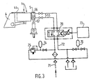
- FIG. 3 gives, by way of example, a diagram of the system 7 for hydraulic supply of the jacks 5.
- the two chambers of the jack are connected by the hoses 56 to the two outputs of a flow servo-valve 70, the inputs of which are connected respectively to supply circuits 71 for pressurized fluid and discharge 72.
- the flow servo-valve 70 which is for example of the mechanical feedback type, is actuated in a known manner under the action of an electrical signal supplied by a control device 73 and can take three positions, respectively a position neutral for which the circuits are cut and two supply positions each of one of the chambers 57, 58 of the jack 5, the other chamber then being connected to the evacuation circuit.
- the supply circuit 71 is produced in a conventional manner and in particular comprises a pressure accumulator 74 making it possible to ensure a constant supply pressure and a pressure limiter 75.
- the discharge circuit 72 is also connected to a pressure accumulator 76 making it possible in particular to force-feed circuits.
- control device 73 can, thanks to mechanical or electrical means that are easy to design, control rapid movements of the servo-valve 70 making it possible to supply the two chambers 57 and 58 of the jack 5 alternately. thus very easily modify during operation not only the frequency of the oscillation but also the amplitude and the speed of the movement to choose the profile of the speed / displacement curves allowing to best adapt to the nuances, formats and casting speed.
- the jacks 5 can either ensure only the oscillation of the ingot mold, the weight of which is then essentially supported by the flexible blades 44, or also serve as a means of supporting the ingot mold, the connecting rod 42 and the blade 44 then serving only for guiding along the pouring axis.
- the oscillation could also be controlled by a single jack then placed in the median plane of symmetry of the mold.
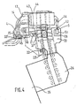
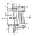
- FIGS. 4 and 5 represent another method of mounting the machine head on the chassis of the guide corset.
- the ingot mold 1 is guided, as just described, by a pair of connecting rods 42 associated with a pair of flexible blades 44 and articulated on two support chairs 4.
- the chassis of the upper element 20 of the corset is supported by pins 21 on forks 37 'which are provided on the upper part of the chassis 25 of the guide corset on which the other segments such as 26 are removably mounted.
- the chassis 25 also carries, for example on a console part, the slides 23 ′ into which guide pins 22 placed at the bottom of the upper cage 20 engage.
- the two support chairs 4 for the connecting rods 42 and the flexible blades 44 are rigidly fixed on the two sides 27 of the chassis of the upper cage 20.
- the pipes 13 and 14 for supplying and discharging the fluid cooling thus, optionally, that the supply and discharge lines of the jack 5 lead to connection members 15 which are fixed on a plate 45 ′ placed at the bottom of one of the support chairs 4 and which is applied to a plate 33 'to which the different circuits end.
- This connection plate 33 ′ is preferably mounted resiliently at the upper part of the chassis so as to be applied to the plate 45 to make the sealed connection of the various circuits, the support of the assembly on the frame of support being however produced by pins 21 and 22.
- the oscillation control means is constituted by a single cylinder 5 placed in the median plane P (FIG. 5) of the ingot mold 1.
- the movements of the two connecting rods 42, 42 'placed on the side and other side of the chassis 12 must be synchronized and, for this purpose, the two connecting rods are fixed on a torsion bar 46 extending from one support chair to the other, on either side of the median plane .
- the body of the jack 5 is rigidly fixed to the chassis 20 of the upper element, the rod of the jack being connected to the chassis 12 of the mold by a connecting rod 54 articulated at its two ends.
- the two sides 27 of the frame 20 of the upper element are connected by a spacer 28 on which the body 51 of the jack is fixed.
- This arrangement has the advantage of allowing the cylinder 5 to be supplied by rigid circuits fixed to one of the sides 27 of the upper element and leading to the connection plate 45.
- the cylinder 5 is then more difficult to protect from steel projections that may occur in the event of a breakout at the outlet of the mold.
- the jack is better protected from steel projections when it is fixed directly to the chassis 12 of the mold, as in the case of FIGS. 1 and 2, but it must then be supplied with hoses either from the work floor 31 either from the connection plate 45.
- the mold is connected, on the one hand with the support frame of the oscillation members and on the other hand with the upper cage and each of these elements must be positioned on the frame or the frame of support by at least two points per side, which multiplies the settings.
- the machine head according to the invention forms a compact, light assembly which is not very dependent on the other parts of the machine.
- the forces involved are lower than in conventional constructions, both in terms of dead masses as for the forces due to friction, which are largely closed between the mold and the upper cage.
- the hydraulic cylinders used for controlling the oscillations of the mold and interposed between the mold and the upper cage are more accessible and better protected in the usual arrangements where the oscillation control mechanism is placed below the floor, near the guide corset proper, that is to say in a wet and dirty one and subjected to high temperatures.
Abstract
Description
L'invention a pour objet une installation de coulée continue de métal et notamment d'acier selon le préambule de la revendication 1.The subject of the invention is an installation for the continuous casting of metal and in particular steel according to the preamble of
On connaît depuis longtemps de telles installations qui, d'une façon générale, comprennent, sur un bâti de support fixe, une lingotière et un dispositif de refroidissement secondaire alignés suivant un axe de coulée.Such installations have been known for a long time, which generally comprise, on a fixed support frame, an ingot mold and a secondary cooling device aligned along a casting axis.
La lingotière est constituée d'un ensemble de parois refroidies par circulation de fluide, délimitant une cavité de coulée sans fond et montées sur un châssis en forme de cadre suffisamment rigide pour maintenir de façon précise le positionnement des parois, celles-ci pouvant éventuellement être déplacées pour régler les dimensions de la cavité de coulée.The mold consists of a set of walls cooled by circulation of fluid, delimiting a bottomless casting cavity and mounted on a frame in the form of a sufficiently rigid frame to precisely maintain the positioning of the walls, these possibly being moved to adjust the dimensions of the casting cavity.
Le dispositif de refroidissement secondaire est constitué lui-même d'un ensemble d'organes de guidage et de refroidissement, généralement des rouleaux ou des plaques de guidage associés à des rampes d'aspersion d'eau, l'ensemble étant monté sur un châssis de support et délimitant ainsi un couloir placé dans le prolongement de la lingotière le long de l'axe de coulée et appelé parfois "corset de guidage".The secondary cooling device itself consists of a set of guide and cooling members, generally rollers or guide plates associated with water spray bars, the set being mounted on a chassis. support and thus delimiting a corridor placed in the extension of the mold along the casting axis and sometimes called "guide corset".
L'acier coulé dans la cavité de la lingotière forme, le long des parois refroidies de celles-ci une croûte dont l'épaisseur augmente vers le bas et qui est évacuée par l'extrémité opposée de la cavité, le produit coulé, constitué d'un noyau liquide enfermé dans la croûte solidifiée, passant alors dans le corset de guidage dont la partie supérieure est placée à proximité de la sortie de la lingotière. Le refroidissement se poursuit à l'intérieur du corset de guidage qui débouche, à sa partie inférieure, dans un organe d'extraction du produit. La coulée peut se faire de façon verticale ou bien de façon courbe, le corset de guidage ramenant à l'hori ontale le produit coulé verticalement.The steel poured into the mold cavity forms, along the cooled walls thereof, a crust whose thickness increases downwards and which is evacuated by the opposite end of the cavity, the cast product, consisting of 'a liquid core enclosed in the solidified crust, then passing into the guide corset, the upper part of which is placed near the outlet of the mold. The cooling continues inside the guide corset which opens, at its lower part, into a product extraction member. The casting can be done vertically or else in a curved manner, the guide corset bringing the product poured vertically to the horizontal point.
Pour que le produit soit évacué facilement de la lingotière, il faut que la croûte solidifiée n'adhère pas aux parois refroidies et c'est pour quoi la lingotière est aminée d'un léger mouvement d'oscillation parallèlement à l'axe de coulée. A cet effet, la lingotière est portée par des organes de support et de guidage permettant des oscillations parallèlement à l'axe de coulée et associés à un moyen de commande des oscillations dont l'amplitude et la fréquence sont réglables en fonction des besoins. Comme le produit est continu et se déplace dans le corset de guidage à une vitesse sensiblement constante, à chaque période du mouvement d'oscillation, la lingotière descend tout d'abord à la même vitesse que le produit, jusqu'à un certain niveau, puis remonte au niveau initial, les parois se décollant alors du produit retenu par le corset de guidage. Pour réaliser ce décollement, les organes de supports et d'oscillation doivent donc exercer sur la lingotière un certain effort. En outre, si la technique de la coulée continue s'est d'abord développée pour réaliser des produits de section relativement faible, on est rapidement passé à des installations beaucoup plus importantes puisque, actuellement, on coule en continu des brames de plus d'un mètre de largeur sur une épaisseur supérieure à 10 mm. La lingotière atteint alors une taille et un poids important et les organes de support, de guidage et de commande d'oscillations doivent être prévus en conséquence. En outre, la lingotière est un organe délicat, qui doit être réglé avec précision et peut être détérioré par des percées de métal, c'est pour quoi elle doit pouvoir être enlevée facilement de l'installation pour entretien ou réglage ou bien pour être remplacée.For the product to be easily removed from the mold, the solidified crust must not adhere to the cooled walls and this is why the mold is made with a slight oscillating movement parallel to the casting axis. For this purpose, the mold is carried by support and guiding members allowing oscillations parallel to the casting axis and associated with an oscillation control means whose amplitude and frequency are adjustable as required. As the product is continuous and moves in the guide corset at a substantially constant speed, at each period of the oscillating movement, the mold first of all descends at the same speed as the product, up to a certain level, then rises to the initial level, the walls then peeling off from the product retained by the guide corset. To achieve this separation, the support and oscillation members must therefore exert a certain effort on the mold. In addition, if the technique of continuous casting was first developed to produce products of relatively small section, we quickly moved to much larger installations since, currently, we continuously slab slabs of more one meter wide and more than 10 mm thick. The mold then reaches a large size and weight and the support, guidance and oscillation control members must be provided accordingly. In addition, the mold is a delicate organ, which must be adjusted with precision and can be damaged by metal breakthroughs, which is why it must be able to be easily removed from the installation for maintenance or adjustment or to be replaced. .
On a donc pris l'habitude de réaliser la lingotière sous forme d'un organe séparé qui peut être fixé de façon amovible sur un support généralement plan et appelé pour cela table d'oscillation, celle-ci étant fixée à demeure sur les moyens de support et de guidage eux-mêmes fixés sur le bâti de l'installation constitué généralement d'une charpente métallique s'appuyant sur un massif en béton.We have therefore got into the habit of making the mold in the form of a separate member which can be fixed in a removable manner on a generally flat support and called for this purpose an oscillation table, the latter being fixed permanently on the means of support and guide themselves fixed on the frame of the installation generally consisting of a metal frame supported on a concrete block.
Le guidage des oscillations peut être assuré par des glissières parallèles à l'axe de coulée et, dans ce cas, pour donner le degré de liberté voulu, le levier de support et d'oscillation, qui comporte normalement deux branches placées de part et d'autre de la lingotière, peut être relié à la table d'oscillation par deux bielles articulées d'un côté sur la table et de l'autre sur chacune des deux branches. Mais les deux branches du levier peuvent également être articulées directement sur la table d'oscillation, cette dernière étant maintenue par deux autres bielles dirigées suivant des directions sensiblement parallèles aux deux branches du levier, l'orientation exacte étant déterminée de façon que le déplacement de la lingotière se fasse suivant l'axe de coulée. Le levier et les bielles de maintien sont articulés sur des paliers portés par des pièces formant des chaises de support posées et fixées sur une plateforme fixe (FR-A 2 055 784).The guidance of the oscillations can be ensured by slides parallel to the casting axis and, in this case, to give the desired degree of freedom, the support and oscillation lever, which normally has two branches placed on the side and d 'other of the mold, can be connected to the oscillation table by two rods articulated on one side on the table and the other on each of the two branches. But the two arms of the lever can also be articulated directly on the oscillation table, the latter being held by two other connecting rods directed in directions substantially parallel to the two arms of the lever, the exact orientation being determined so that the displacement of the mold is made along the casting axis. The lever and the connecting rods are articulated on bearings carried by parts forming support chairs placed and fixed on a fixed platform (FR-A 2 055 784).
Le levier est animé d'un mouvement alternatif par un mécanisme de commande d'oscillation qui, le plus souvent, est un mécanisme à excentrique monté sur le bâti du support en un point relativement écarté de la lingotière, au-dessous du plancher de travail. Les efforts dus au poids de la lingotière et à l'effet de décollement, éventuellement amplifiés par les leviers, sont assez importants et sont encaissés par les paliers des axes d'articulation. Ces organes sont donc, dans l'ensemble, lourds et coûteux et sont soumis à une usure relativement importante du fait de la fréquence élevée des mouvements d'oscillations et des charges appliquées.The lever is reciprocated by an oscillation control mechanism which, most often, is an eccentric mechanism mounted on the support frame at a point relatively distant from the mold, below the work floor . The forces due to the weight of the mold and the detachment effect, possibly amplified by the levers, are quite significant and are collected by the bearings of the hinge pins. These bodies are therefore, overall, heavy and expensive and are subject to relatively significant wear due to the high frequency of the oscillations and loads applied.
Dans de telles installations, les leviers d'oscillation assurent simultanément le support, le guidage et la commande d'oscillations de la lingotière et doivent donc être dimensionnés en conséquence. Pour s'implifier et alléger les mécanismes, on a déjà proposé (DE-A 2 248 066, sur lequel le préambule de la revendication 1 est basé) de séparer les fonctions de guidage et de commande des oscillations, celles-ci étant appliquées directement sur la lingotière, au moyen d'un ou deux vérins prenant appui sur la charpente. Les leviers d'oscillations sont alors supprimés, le support et le maintien de la lingotière sur sa trajectoire étant assurés par deux paires de lames flexibles fixés à leurs extrémités, respectivement sur la lingotière et sur la charpente.In such installations, the oscillation levers simultaneously provide support, guidance and control of oscillations of the mold and must therefore be dimensioned accordingly. To get involved and lighten the mechanisms, it has already been proposed (DE-A 2 248 066, on which the preamble of
Cependant, une telle disposition ne permet pas un enlèvement facile de la lingotière pour entretien ou remplacement puisque les lames flexibles devraient être démontées et remontées à chaque fois.However, such an arrangement does not allow easy removal of the mold for maintenance or replacement since the flexible blades should be dismantled and reassembled each time.
De plus, que l'on utilise les leviers et des bielles de guidage ou bien des lames flexibles, dans tous les cas, ces organes et leurs attaches sont soumis à des efforts périodiques dûs au décollement de la lingotière à chaque remontée de celle-ci et qui entraînent une usure assez rapide.In addition, whether the levers and guide rods or flexible blades are used, in all cases, these members and their fasteners are subjected to periodic forces due to the detachment of the mold each time it is raised. and which lead to fairly rapid wear.
L'invention a pour object une nouvelle disposition permettant de diminuer les efforts mis en jeu, tant pour ce qui est des masses mortes que pour les frottements, de telle sorte que l'ensemble soit moins coûteux et d'entretien plus facile.The object of the invention is to provide a new arrangement making it possible to reduce the forces involved, both with regard to dead masses and for friction, so that the assembly is less expensive and easier to maintain.
Conformément à l'invention, le dispositif de refroidissement secondaire étant constitué d'un ensemble d'organes de guidage et de refroidissement du produit coulé montés sur un châssis de support et délimitant un corset de guidage s'étendant entre une partie supérieure placée immédiatement après la sortie de la cavité de coulée et une partie inférieure débouchant dans un organe d'extraction, le moyen de commande des oscillations prend appui directement, d'un côté opposé à la lingotière, sur la partie supérieure du châssis de support des organes de guidage et de refroidissement.According to the invention, the secondary cooling device consisting of a set of guide and cooling elements for the cast product mounted on a support frame and delimiting a guide corset extending between an upper part placed immediately after the outlet of the casting cavity and a lower part opening into an extraction member, the oscillation control means bears directly, on a side opposite to the mold, on the upper part of the support frame for the guide members and cooling.
Compte tenu de la fragilité de la croûte solidifiée à la sortie de la lingotière, la partie supérieure du corset de guidage est constituée généralement d'un élément de refroidissement réalisé de façon particulière et formant une cage supérieure que l'on peut enlever facilement du reste du corset de guidage pour entretien, réparation ou remplacement rapide par une cage de rechange, les risques de percées, et par conséquent d'avaries, étant plus grands dans cette one. En particulier, la lingotière étant placée normalement au niveau d'un plancher de travail qui recouvre l'ensemble de l'installation placé au-dessous. Il est intéressant de pouvoir retirer en même temps la lingotière et l'élément supérieur du corset placé immédiatement au-dessous de celle-ci alors que le remplacment éventuel des autres parties du corset, qui se fait moins souvent, peut être réalisé de façon différente.Given the fragility of the solidified crust at the outlet of the mold, the upper part of the guide corset generally consists of a cooling element produced in a particular way and forming an upper cage which can be easily removed from the rest of the guide corset for maintenance, repair or rapid replacement by a spare cage, the risks of breakthroughs, and consequently of damage, being greater in this one. In particular, the mold is normally placed at a working floor which covers the entire installation placed below. It is advantageous to be able to remove at the same time the mold and the upper element of the corset placed immediately below it while the possible replacement of the other parts of the corset, which is done less often, can be carried out differently. .
En outre, il faut veiller avec un soin particulier à l'alignement de la lingotière animée de mouvements d'oscillation avec la cage de refroidissement qui lui fait suite et qui, elle, est fixe. Il est intéressant de réaliser cet alignement en un endroit éloigné de l'installation de façon à pouvoir remplacer l'ensemble de la lingotière et de la cage supérieure par un autre ensemble préparé à l'avance. A cet effet, l'élément supérieur de refroidissement, qui est monté de façon amovible sur le bâti de l'installation, est muni de moyens de fixation amovibles avec la lingotière et de moyens d'accrochage sur un palonnier de levage qui permet d'enlever en même temps l'élément supérieur avec la lingotière qui repose alors sur celui-ci. Le réglage du positionnement relatif des deux organes est réalisé sur un chantier de support puis l'on remet en place l'ensemble, la lingotière posée sur l'élément supérieur venant d'abord s'appliquer sur la table d'oscillation restée fixe et l'élément supérieur continuant sa descente jusqu'à des organes d'appui ménagés sur le bâti fixe.In addition, special care must be taken to align the ingot mold with oscillating movements with the cooling cage which follows it and which is fixed. It is advantageous to carry out this alignment at a location remote from the installation so as to be able to replace the assembly of the ingot mold and of the upper cage with another assembly prepared in advance. For this purpose, the upper cooling element, which is removably mounted on the frame of the installation, is provided with removable fixing means with the ingot mold and means for hooking on a lifting beam which allows remove the upper element at the same time with the mold which then rests on it. The relative positioning of the two members is adjusted on a support site and then the assembly is replaced, the mold placed on the upper element first being applied to the oscillation table which has remained fixed and the upper element continuing its descent to support members formed on the fixed frame.
Pour mettre en oeuvre cette technique d'entretien et de remplacement, on a été amené à renforcer le châssis de l'élément supérieur du corset qui sert alors d'organe de transport de la lingotière. L'invention met à profit cette disposition particulière et ce renforcement de la partie supérieure du corset de guidage. En effet, selon une caractéristique particulièrement avantageuse, le moyen de commande des oscillation est fixé d'un côté sur le châssis de la lingotière et de l'autre sur le châssis de l'élément supérieur de refroidissement.To implement this maintenance and replacement technique, it was necessary to reinforce the chassis of the upper element of the corset which then serves as a transport member for the mold. The invention takes advantage of this particular arrangement and this reinforcement of the upper part of the guide corset. Indeed, according to a particularly advantageous characteristic, the oscillation control means is fixed on one side on the chassis of the mold and on the other on the chassis of the upper cooling element.
Selon une autre caractéristique préférentielle, le moyen de commande des oscillations est un vérin hydraulique, de préférence à double effet, comprenant un corps et un piston reliés respectivement, par au moins deux liaisons articulées, l'un au châssis de la lingotière et l'autre au châssis de la partie supérieure du corset de guidage.According to another preferred characteristic, the means for controlling the oscillations is a hydraulic jack, preferably double-acting, comprising a body and a piston connected respectively, by at least two articulated connections, one to the chassis of the mold and the another to the frame of the upper part of the guide corset.
Ce vérin peut, avantageusement, constituer lui-même l'organe de support de la lingotière qui doit simplement être maintenu sur sa trajectoire par des organes de guidage. Ces derniers ne sont pas soumis aux efforts dus au poids de la lingotière et au décollement de la croute solidifiée et peuvent être constitués de glissières ou bien de bielles articulées sur une pièce de support qui selon une caractéristique supplémentaire de l'invention, peut être fixée directement sur le châssis de la cage supérieure de refroidissement.This cylinder can advantageously constitute itself the support member of the mold which must simply be kept in its path by guide members. The latter are not subjected to the forces due to the weight of the mold and the detachment of the solidified crust and can consist of slides or else connecting rods articulated on a support piece which, according to an additional characteristic of the invention, can be fixed. directly on the chassis of the upper cooling cage.
Dans ce cas, la lingotière et ses moyens de support, de guidage et de commande des oscillations, constituent avec l'élément supérieur de refroidissement un ensemble compact et homogène, démontable et remontable en bloc et sur lequel les réglages d'alignement et d'amplitude des oscillations peuvent être effectués en dehors de l'installation et maintenus en cours de fonctionnement avec toute la fidélité souhaitable.In this case, the mold and its means for supporting, guiding and controlling the oscillations, constitute, with the upper cooling element, a compact and homogeneous unit, which can be dismantled and reassembled in block and on which the alignment and amplitude of the oscillations can be carried out outside the installation and maintained during operation with all the desired fidelity.
Mais l'invention présente d'autres avantages et sera mieux comprise par la description qui va suivre de certains modes de réalisation particuliers, donnés à titre d'exemples et représentés sur les dessins annexés.
- La figure 1 est une vue schématique de face de la partie supérieure d'une installation de coulée selon l'invention.
- La figure 2 est une vue de côté de l'installation de la figure 1.
- La figure 3 est un schéma hydraulique de commande du vérin d'oscillation.
- La figure 4 est une vue de côté d'une installation plus perfectionnée.
- La figure 5 est une vue de face de l'installation représentée figure 4.
- Figure 1 is a schematic front view of the upper part of a casting installation according to the invention.
- Figure 2 is a side view of the installation of Figure 1.
- FIG. 3 is a hydraulic diagram for controlling the oscillation cylinder.
- Figure 4 is a side view of a more sophisticated installation.
- FIG. 5 is a front view of the installation shown in FIG. 4.
Sur les figures 1 et 2, on a représenté la partie supérieure d'une installation de coulée continue comprenant une lingotière 1 et un dispositif de refroidissement secondaire 2 formant un corset de guidage dont au moins la partie supérieure est constituée d'une cage séparée 20.FIGS. 1 and 2 show the upper part of a continuous casting installation comprising an
La lingotière 1 constitue un moule sans fond ménageant une cavité de coulée limitée par des parois refroidies 11 portées par un châssis 12.The
L'ensemble de l'installation qui, étant bien connu, n'a été représenté que schématiquement sur la figure 1, est porté par une charpente de support ou un massif en béton 3 et surmonté par un plancher de travail 31 au-dessus duquel dépasse seulement la lingotière 1.The entire installation which, being well known, has only been shown schematically in FIG. 1, is carried by a support frame or a
Le corset de guidage 2 comprend, de façon classique, deux séries de rouleaux de guidage 24 placés de part et d'autre du produit, associés à des rampes d'aspersion non représentée et montés sur un bâti de support 25. Les rouleaux 24 peuvent être regroupés en segments comprenant chacun un cadre 26 de support de plusieurs paires de rouleaux, monté de façon amovible sur le bâti 25.The
De façon également connue, ce dernier s'appuie sur le massif de fondation 3 d'une façon permettant notamment sa dilatation.In a manner that is also known, the latter rests on the
Dans l'exemple représenté la lingotière 1 et la cage supérieure 20 sont portées par une plateforme fixe 33 ménagée à la partie supérieure du massif de fondation 3, au-dessous du niveau du plancher de coulée 31 et sur laquelle sont fixés, éventuellement de façon amovible, les moyens de support et guidage de la lingotière.In the example shown, the
Différents dispositifs peuvent être utilisés, de façon connue, pour assurer le support et le guidage de la lingotière.Different devices can be used, in known manner, to provide support and guidance for the mold.
Cependant, comme on l'a indiqué, dans les installations classiques, la lingotière est fixé sur une table qui est supportée par un levier articulé autour d'un axe horiontal fixe et relié à un mécanisme d'oscillation.However, as indicated, in conventional installations, the mold is fixed on a table which is supported by a lever articulated around a fixed horiontal axis and connected to an oscillation mechanism.
Au contraire, dans l'installation selon l'invention, la table d'oscillation peut être supprimée. En effet, le mouvement d'oscillation est réalisé par un ou deux vérins hydrauliques 5 dont le corps 51 est fixé rigidement directement sur le châssis 12 de la lingotière alors que la tige de chaque vérin prend appui directement sur le châssis de la cage supérieure 20 au moyen d'une bielle 54. La cage supérieure 20 s'appuyant elle-même directement sur le bâti de support, le poids de la lingotière est supporté par les vérins d'oscillation 5. De ce fait, la lingotière doit simplement être guidée dans son mouvement d'oscillation et, dans l'exemple représenté, on utilise à cet effet une paire de bielles 42 placées sur les deux côtés du châssis au-dessous de celui-ci, et articulées autour d'un axe 43 sur le châssis 12 et autour d'un axe 41, respectivement sur deux chaises de support 4 comportant chacune une plaque d'appui 45 qui peut venir s'appliquer sur une plateforme hori ontale 33 ménagée à la partie supérieure du massif de fondation 3. De façon connue, les conduits d'alimentation 13 et d'évacuation 14 en fluide de refroidissement sont reliées à des circuits fixes 16 par des organes de connection amovibles et étanches 15 comprenant deux parties fixées respectivement sur les plaques d'appui 45 et sur la plateforme 33 et qui s'engagent l'une dans l'autre lorsque les chaises de support 4 sont appliquées sur la plateforme 33. Pour être maintenu en position verticale, le châssis 12 de la lingotière doit être soutenu par une seconde paire de bielles de maintien articulées sur la chaise de support 4 et sur le châssis 12. Selon une disposition particulière, la deuxième paire de bielles de maintien peut être remplacée par des lames flexibles 44 fixées à leurs extrémités sur les chaises de support 4 et sur le châssis 12, des deux côtés de celui-ci, ce qui allège encore l'ensemble.On the contrary, in the installation according to the invention, the oscillation table can be omitted. Indeed, the oscillation movement is achieved by one or two
- Dans l'exemple représenté, l'élément supérieur 20 du corset de guidage s'appuie séparément sur le bâti de support. Par exemple, la plateforme 33 étant ménagée sur un châssis fixe 32, celui-ci peut porter des organes d'appui en forme de fourche 37 placés de part et d'autre de l'élément supérieur 20 et dans lesquels viennent reposer des broches 21 fixées sur les deux côtés du châssis 27 de la cage 20. Pour assurer la continuité du guidage,cette dernière est munie à sa partie inférieure de deux autres broches 22 qui coulissent dans des guidages 23 ménagés à la partie supérieure du corset, soit, directement soit sur le bâti de support, soit de préférence sur le cadre 26 de support des rouleaux du segment du corset suivant la cage supérieure 20. De la sorte, après avoir libéré les plaques d'appui 45 de la plateforme 33, il est possible, au moyen d'élingues non représentées, d'enlever vers le haut la cage supérieure 20 qui vient s'appliquer sur le châssis 12 de la lingotière. Après avoir fixé ce dernier sur le châssis de la cage 20 au moyen d'organes de verrouillage amovibles, on peut enlever simultanément la lingotière avec son châssis, le vérin d'oscillation 5 et les moyens de guidage avec leurs chaises de support 4, l'ensemble étant supporté par la cage supérieure 20.- In the example shown, the
On voit ainsi que les dispositions selon l'invention permettent d'enlever en bloc non seulement la lingotière et l'élément supérieur 20 mais également l'ensemble des moyens de support, de guidage et de commande des oscillations. De la sortie, on peut régler en atelier avec précision tous les éléments qui participent à l'oscillation de la lingotière et également l'amplitude des mouvements d'oscillation commandés par le vérin 5.It can thus be seen that the arrangements according to the invention make it possible to remove in block not only the mold and the
Lorsque l'on replace l'ensemble sur l'installation, les plaques d'appui 45 viennent s'appliquer sur la plateforme de support 33 puis la cage supérieure 20, déchargée de la lingotière, vient reposer par les broches 21 dans les fourches 37, les broches 22 s'engageant dans les glissières 23 du segment 26.When the assembly is replaced on the installation, the
Bien entendu, il serait également possible, en démontant la bielle 54 et en prévoyant un élinguage adéquat du châssis 12 de la lingotière et/ou des chaises de support 4, de retirer uniquement la lingotière et ses moyens de supports et de guidage en laissant en place l'élément supérieur 20 qui, dans ce cas, s'appuierait séparément sur le bâti 25 du corset.Of course, it would also be possible, by dismantling the connecting
On constate cependant que l'un des avantages essentiels de l'invention réside dans le fait que, les vérins d'oscillation prenant appui directement sur les châssis de la lingotère et de la cage supérieure 20 entre lesquels s'exercent précisément l'effort de décollage des parois de la lingotière, l'intégration de tous les éléments de support et de guidage dans un même ensemble permet de réaliser un bouclage des efforts et par conséquent d'alléger les bielles 42 et 44 qui assurent uniquement un rôle de guidage. De même, les articulations 41 et 43 ne sont plus soumises à des efforts importants et peuvent donc être réalisées de façon plus simple et plus légère.However, it can be seen that one of the essential advantages of the invention resides in the fact that, the oscillation cylinders bearing directly on the chassis of the ingot mold and of the
Les vérins 5 de commande des oscillations de la lingotière sont, de préférence, des vérins à double effet dont les deux chambres sont reliées à des moyens d'alimentation en huile 55 par des flexibles 56 permettant les mouvements d'oscillation de la lingotière.The
La figure 3 donne, à titre d'exemple, un schéma du système 7 d'alimentation hydraulique des vérins 5.FIG. 3 gives, by way of example, a diagram of the system 7 for hydraulic supply of the
Les deux chambres du vérin sont reliées par les flexibles 56 aux deux sorties d'une servo-valve de débit 70 dont les entrées sont reliées respectivement à des circuits d'alimentation 71 en fluide sous pression et d'évacuation 72.The two chambers of the jack are connected by the
La servo-valve de débit 70, qui est par exemple du type à contre-réaction mécanique, est actionnée de façon connue sous l'action d'un signal électrique fourni par un dispositif de commande 73 et peut prendre trois positions, respectivement une position neutre pour laquelle les circuits sont coupés et deux positions d'alimentation chacune de l'une des chambres 57, 58 du vérin 5, l'autre chambre étant alors reliée au circuit d'évacuation.The flow servo-
Le circuit d'alimentation 71 est réalisé de façon classique et comprend notamment un accumulateur de pression 74 permettant d'assurer une pression d'alimentation constante et un limiteur de pression 75. Le circuit d'évacuation 72 est également relié à un accumulateur de pression 76 permettant notamment d'assurer le gavage des circuits.The
On conçoit que le dispositif de commande 73 peut, grâce à des moyens mécaniques ou électriques faciles à concevoir, commander des mouvements rapides de la servo-valve 70 permettant d'alimenter al- temativement les deux chambres 57 et 58 du vérin 5. On peut ainsi très facilement modifier en cours de fonctionnement non seulement la fréquence de l'os- ciallation mais également l'amplitude et la vitesse du mouvement pour choisir le profil des courbes vites- se/déplacement permettant de s'adapter au mieux aux nuances, formats et vitesse de coulée.It will be appreciated that the
Par ailleurs, selon les pressions utilisées, les vérins 5 peuvent, soit assurer uniquement l'oscillation de la lingotière, dont le poids est alors supporté essentiellement par les lames flexibles 44, soit servir également de moyen de support de la lingotière, la bielle 42 et la lame 44 servant alors seulement au guidage suivant l'axe de coulée.Furthermore, depending on the pressures used, the
Bien entendu, l'oscillation pourrait être commandée également par un seul vérin placé alors dans le plan médian de symétrie de la lingotière.Of course, the oscillation could also be controlled by a single jack then placed in the median plane of symmetry of the mold.
Une telle disposition a été figurée à titre d'exemple sur les figures 4 et 5 qui représentent un autre mode de montage de la tête de machine sur le châssis du corset de guidage.Such an arrangement has been shown by way of example in FIGS. 4 and 5 which represent another method of mounting the machine head on the chassis of the guide corset.
La lingotière 1 est guidée, de la façon que l'on vient de décrire, par une paire de bielles 42 associées à une paire de lames flexibles 44 et articulées sur deux chaises de support 4. Cependent, le châssis de l'élément supérieur 20 du corset s'appuie par des broches 21 sur des fourches 37' qui sont ménagées sur la partie supérieure du châssis 25 du corset de guidage sur lequel sont montés de façon amovible les autres segments tels que 26. Le châssis 25 porte également, par exemple sur une partie en console, les glissières 23' dans lesquels s'engagent des broches de guidage 22 placées à la partie inférieure de la cage supérieure 20.The
Dans ce mode de réalisation, les deux chaises de support 4 des bielles 42 et des lames flexibles 44 sont fixées rigidement sur les deux côtés 27 du châssis de la cage supérieure 20. Les conduites 13 et 14 d'alimentation et d'évacuation du fluide de refroidissement ainsi, éventuellment, que les conduites d'alimentation et d'évacuation du vérin 5 aboutissent à des organes de connexion 15 qui sont fixés sur une plaque 45' placée à la partie inférieure de l'une des chaises de support 4 et qui vient s'appliquer sur une plaque 33' à laquelle aboutissent les différents circuits. Cette plaque de connexion 33' est, de préférence montée de façon élastique à la partie supérieure du châssis de façon à venir s'appliquer sur la plaque 45 pour réaliser le branchement étanche des différents circuits, l'appui de l'ensemble sur le bâti de support étant cependant réalisé par les broches 21 et 22.In this embodiment, the two support chairs 4 for the connecting
Dans ce mode de réalisation, le moyen de commande des oscillations est constitué par un vérin uniuqe 5 placé dans le plan médian P (figure 5) de la lingotière 1. Dans ce cas, le mouvements des deux bielles 42, 42' placées de part et d'autre du châssis 12 doivent être synchronisés et, à cet effet, les deux bielles sont calées sur une barre de torsion 46 s'étendant d'une chaise de support à l'autre, de part et d'autre du plan médian.In this embodiment, the oscillation control means is constituted by a
Dans le mode de réalisation représenté sur les figures 4 et 5,le corps du vérin 5 est fixé rigidement sur le châssis 20 de l'élément supérieur, la tige du vérin étant reliée au châssis 12 de la lingotière par une bielle 54 articulée à ses deux extrémités. Dans ce cas, les deux côtés 27 du châssis 20 de l'élément supérieur sont reliés par une entretoise 28 sur laquelle est fixé le corps 51 du vérin.In the embodiment shown in FIGS. 4 and 5, the body of the
Cette disposition présente l'avantage de permettre l'alimentaiton du vérin 5 par des circuits rigides fixés sur l'un des côtés 27 de l'élément suprieur et aboutissant à la plaque de connexion 45. Cependant, le vérin 5 est alors plus difficile à protéger des projections d'acier pouvant survenir en cas de percée à la sortie de la lingotière. En revanche, le vérin est mieux protégé des projections d'acier lorsque il est fixé directement sur le châssis 12 de la lingotière, comme dans le cas des figures 1 et 2, mais il faut alors l'alimenter par des flexibles soit à partir du plancher de travail 31 soit à partir de la plaque de connexion 45.This arrangement has the advantage of allowing the
On voit que les dispositions selon l'invention présentent de nombreux avantages, en particulier du fait que tous les moyens d'oscillation et de guidage sont intégrés à l'ensemble formé par la lingotière et la cage et les liaisons avec la machine peuvent être réduites à deux points d'acrochage par côté, de sorte que l'ajustement est très simplifié et aisément contrôlable.It can be seen that the arrangements according to the invention have numerous advantages, in particular because all the oscillation and guidance means are integrated into the assembly formed by the ingot mold and the cage and the connections with the machine can be reduced. with two attachment points per side, so that the adjustment is very simplified and easily controllable.
Dans les solutions classiques au contraire, la lingotière est reliée, d'une part avec le châssis de support des organes d'oscillation et d'autre part avec la cage supérieure et chacun de ces éléments doit être positionné sur la charpente ou le bâti de support par deux points au moins par côté, ce qui multiplie les réglages. Au contraire, la tête de machine selon l'invention forme un ensemble compact, léger et peu dépendant des autres parties de la machine.In conventional solutions on the contrary, the mold is connected, on the one hand with the support frame of the oscillation members and on the other hand with the upper cage and each of these elements must be positioned on the frame or the frame of support by at least two points per side, which multiplies the settings. On the contrary, the machine head according to the invention forms a compact, light assembly which is not very dependent on the other parts of the machine.
En outre, les efforts mis en jeu sont plus faibles que dans les constructions classiques, tant pour ce qui est des masses mortes que pour les efforts dus aux frottements, qui sont en grande partie refermés entre la lingotière et la cage supérieure. De plus, les vérins hydrauliques utilisés pour la commande des oscillations de la lingotière et interposés entre la lingotière et la cage supérieure, sont plus accessibles et mieux protégés dans les dispositions habituelles où l'on place le mécanisme de commande des oscillations au-dessous du plancher, à proximité du corset de guidage proprement dit, c'est-à-dire dans une one humide et sale et soumise à de hautes températures.In addition, the forces involved are lower than in conventional constructions, both in terms of dead masses as for the forces due to friction, which are largely closed between the mold and the upper cage. In addition, the hydraulic cylinders used for controlling the oscillations of the mold and interposed between the mold and the upper cage, are more accessible and better protected in the usual arrangements where the oscillation control mechanism is placed below the floor, near the guide corset proper, that is to say in a wet and dirty one and subjected to high temperatures.
Mais l'invention n'est évidemment pas limitée aux seuls modes de réalisation qui viennent d'être décrits, des perfectionnements ou des dispositions équivalentes pourront être utilisés en restant dans le cadre de protection défini par les revendications.However, the invention is obviously not limited only to the embodiments which have just been described, improvements or equivalent provisions could be used while remaining within the protective framework defined by the claims.
En particulier, on a décrit un système de guidage des oscillations par bielles ou lames flexibles mais l'invention serait également utilisable dans le cas d'un guidage par glissière ou par galets.In particular, a system for guiding the oscillations by connecting rods or flexible blades has been described, but the invention would also be usable in the case of guidance by a slide or by rollers.
De même, il serait possible de faire supporter le poids de la lingotière sur la cage supérieure par des ressorts, pour diminuer les efforts appliqués sur le moyen de commande des oscillations. Celles-ci pourraient d'ailleurs être déterminées par d'autres moyens qu'un vérin hydraulique, par exemple un dispositif électrique à moteur linéaire, une bobine à, noyau plongeur ou tout autre système électromécanique de faible encombrement.Similarly, it would be possible to support the weight of the mold on the upper cage by springs, to reduce the forces applied to the oscillation control means. These could also be determined by other means than a hydraulic cylinder, for example an electric device with linear motor, a coil, plunger core or any other electromechanical system of small size.
Claims (18)
Priority Applications (1)
| Application Number | Priority Date | Filing Date | Title |
|---|---|---|---|
| AT87400491T ATE52432T1 (en) | 1986-03-07 | 1987-03-05 | CONTINUOUS CASTING PLANT FOR METAL. |
Applications Claiming Priority (2)
| Application Number | Priority Date | Filing Date | Title |
|---|---|---|---|
| FR8603282 | 1986-03-07 | ||
| FR8603282A FR2598338B1 (en) | 1986-03-07 | 1986-03-07 | CONTINUOUS CASTING OF METAL |
Publications (2)
| Publication Number | Publication Date |
|---|---|
| EP0236237A1 EP0236237A1 (en) | 1987-09-09 |
| EP0236237B1 true EP0236237B1 (en) | 1990-05-09 |
Family
ID=9332898
Family Applications (1)
| Application Number | Title | Priority Date | Filing Date |
|---|---|---|---|
| EP87400491A Expired - Lifetime EP0236237B1 (en) | 1986-03-07 | 1987-03-05 | Continuous casting machine for metal |
Country Status (6)
| Country | Link |
|---|---|
| US (1) | US4765392A (en) |
| EP (1) | EP0236237B1 (en) |
| JP (1) | JPS62275553A (en) |
| AT (1) | ATE52432T1 (en) |
| DE (1) | DE3762579D1 (en) |
| FR (1) | FR2598338B1 (en) |
Families Citing this family (5)
| Publication number | Priority date | Publication date | Assignee | Title |
|---|---|---|---|---|
| US5219029A (en) * | 1992-03-09 | 1993-06-15 | Gunther Behrends | Oscillator for continuous casting mold |
| DE4341719C2 (en) * | 1993-12-03 | 2001-02-01 | Mannesmann Ag | Device for the continuous casting of steel |
| DE19722733A1 (en) * | 1997-05-30 | 1998-12-03 | Schloemann Siemag Ag | Device for the continuous casting of steel |
| US5911268A (en) * | 1997-10-16 | 1999-06-15 | Custom Systems, Inc. | Oscillating mold table assembly |
| DE102010054398A1 (en) * | 2010-12-08 | 2012-06-14 | Sms Siemag Ag | continuous casting plant |
Family Cites Families (7)
| Publication number | Priority date | Publication date | Assignee | Title |
|---|---|---|---|---|
| US3040397A (en) * | 1958-12-17 | 1962-06-26 | Koppers Co Inc | Continuous casting machine |
| US3528482A (en) * | 1967-12-20 | 1970-09-15 | Concast Inc | Continuous casting machine |
| US3664409A (en) * | 1969-08-08 | 1972-05-23 | Kolomeitsev Adolf P | Mold rocking mechanism in a continuous metal casting plant |
| FR2055784A1 (en) * | 1969-08-18 | 1971-04-30 | Ural Z Tyaznlloco | Mould rocking mechanism in continuous metal - casting plants |
| DE2248066A1 (en) * | 1972-09-30 | 1974-04-04 | Schloemann Ag | Continuous casting mould vibration mounting - comprises two horizontal leaf spring packs |
| AT370355B (en) * | 1981-09-17 | 1983-03-25 | Voest Alpine Ag | CONTINUOUS CASTING SYSTEM WITH AN OSCILLATING LIFTING TABLE |
| US4483385A (en) * | 1981-11-05 | 1984-11-20 | Amb Technology, Inc. | System for oscillating mold tube in continuous steel casting machine |
-
1986
- 1986-03-07 FR FR8603282A patent/FR2598338B1/en not_active Expired
-
1987
- 1987-03-05 AT AT87400491T patent/ATE52432T1/en not_active IP Right Cessation
- 1987-03-05 DE DE8787400491T patent/DE3762579D1/en not_active Expired - Lifetime
- 1987-03-05 EP EP87400491A patent/EP0236237B1/en not_active Expired - Lifetime
- 1987-03-07 JP JP62052842A patent/JPS62275553A/en active Pending
- 1987-03-09 US US07/023,745 patent/US4765392A/en not_active Expired - Fee Related
Also Published As
| Publication number | Publication date |
|---|---|
| DE3762579D1 (en) | 1990-06-13 |
| ATE52432T1 (en) | 1990-05-15 |
| JPS62275553A (en) | 1987-11-30 |
| FR2598338B1 (en) | 1989-10-06 |
| US4765392A (en) | 1988-08-23 |
| FR2598338A1 (en) | 1987-11-13 |
| EP0236237A1 (en) | 1987-09-09 |
Similar Documents
| Publication | Publication Date | Title |
|---|---|---|
| EP0711214B1 (en) | Continuous casting ingot mould | |
| EP0236237B1 (en) | Continuous casting machine for metal | |
| FR2583662A1 (en) | METHOD AND CONTINUOUS CASTING MACHINE OF A THIN METAL PRODUCT | |
| BE475159A (en) | ||
| FR2459698A1 (en) | METHOD AND INSTALLATION OF CENTRIFUGAL CASTING | |
| CH644288A5 (en) | METHOD AND MACHINE FOR CONTINUOUS CASTING OF METAL. | |
| WO1995005910A1 (en) | Continuous casting ingot mould | |
| EP0379420B1 (en) | Device and method for feeding with molten metal for pressure die casting metallic products | |
| FR2561146A1 (en) | CENTRIFUGAL CASTING METHOD AND DEVICE | |
| EP0233796B1 (en) | Continuous casting machines | |
| EP0379407B1 (en) | Pressure casting mould for flat metallic products such as slabs | |
| EP0697930B1 (en) | Device for controlling the motions of an ingot mold | |
| EP0455619B1 (en) | A device for metal casting and a method of operating such device | |
| EP1426126B1 (en) | Control assembly for a closing member in a continuous casting machine, and corresponding continuous casting machine | |
| EP0203867B1 (en) | Apparatus for casting metal strips | |
| EP0379419B1 (en) | Device for supporting and controlling the position of a top bolt in a mould for pressure die casting metallic plate products or slabs | |
| EP0778098B1 (en) | Electromagnetic agitating method for continuous casting | |
| CA1237268A (en) | Holding device for molded part issuing from a continuous molding machine, and means of control for said device | |
| EP0379418B1 (en) | Method of die pressure casting metallic plates or slabs and installation for carrying out this method | |
| EP0206869B1 (en) | Continuous-casting machine for sheet metal | |
| FR2652020A1 (en) | Method and device for reducing the thickness of a continuously cast slab | |
| EP0943380A1 (en) | Process and installation for continuous casting of metals | |
| FR2607738A3 (en) | Device for supplying continuous-cast ingot moulds with molten metal | |
| CH625145A5 (en) | Continuous-casting installation including an ingot mould and a guiding device | |
| BE662821A (en) |
Legal Events
| Date | Code | Title | Description |
|---|---|---|---|
| PUAI | Public reference made under article 153(3) epc to a published international application that has entered the european phase |
Free format text: ORIGINAL CODE: 0009012 |
|
| AK | Designated contracting states |
Kind code of ref document: A1 Designated state(s): AT DE FR |
|
| 17P | Request for examination filed |
Effective date: 19871014 |
|
| 17Q | First examination report despatched |
Effective date: 19890105 |
|
| RAP1 | Party data changed (applicant data changed or rights of an application transferred) |
Owner name: CLECIM |
|
| GRAA | (expected) grant |
Free format text: ORIGINAL CODE: 0009210 |
|
| AK | Designated contracting states |
Kind code of ref document: B1 Designated state(s): AT DE FR |
|
| PG25 | Lapsed in a contracting state [announced via postgrant information from national office to epo] |
Ref country code: AT Effective date: 19900509 |
|
| REF | Corresponds to: |
Ref document number: 52432 Country of ref document: AT Date of ref document: 19900515 Kind code of ref document: T |
|
| REF | Corresponds to: |
Ref document number: 3762579 Country of ref document: DE Date of ref document: 19900613 |
|
| PLBE | No opposition filed within time limit |
Free format text: ORIGINAL CODE: 0009261 |
|
| STAA | Information on the status of an ep patent application or granted ep patent |
Free format text: STATUS: NO OPPOSITION FILED WITHIN TIME LIMIT |
|
| 26N | No opposition filed | ||
| PGFP | Annual fee paid to national office [announced via postgrant information from national office to epo] |
Ref country code: FR Payment date: 19980226 Year of fee payment: 12 |
|
| PGFP | Annual fee paid to national office [announced via postgrant information from national office to epo] |
Ref country code: DE Payment date: 19980325 Year of fee payment: 12 |
|
| PG25 | Lapsed in a contracting state [announced via postgrant information from national office to epo] |
Ref country code: FR Free format text: LAPSE BECAUSE OF NON-PAYMENT OF DUE FEES Effective date: 19991130 |
|
| REG | Reference to a national code |
Ref country code: FR Ref legal event code: ST |
|
| PG25 | Lapsed in a contracting state [announced via postgrant information from national office to epo] |
Ref country code: DE Free format text: LAPSE BECAUSE OF NON-PAYMENT OF DUE FEES Effective date: 20000101 |