EP0236166A1 - Process and installation for circulating fluids by pumping - Google Patents
Process and installation for circulating fluids by pumping Download PDFInfo
- Publication number
- EP0236166A1 EP0236166A1 EP87400158A EP87400158A EP0236166A1 EP 0236166 A1 EP0236166 A1 EP 0236166A1 EP 87400158 A EP87400158 A EP 87400158A EP 87400158 A EP87400158 A EP 87400158A EP 0236166 A1 EP0236166 A1 EP 0236166A1
- Authority
- EP
- European Patent Office
- Prior art keywords
- liquid
- pump
- turbine
- fluid
- inlet
- Prior art date
- Legal status (The legal status is an assumption and is not a legal conclusion. Google has not performed a legal analysis and makes no representation as to the accuracy of the status listed.)
- Granted
Links
- 238000009434 installation Methods 0.000 title claims abstract description 11
- 239000012530 fluid Substances 0.000 title claims description 35
- 238000000034 method Methods 0.000 title claims description 14
- 238000005086 pumping Methods 0.000 title claims description 9
- 239000007788 liquid Substances 0.000 claims description 36
- 239000007789 gas Substances 0.000 claims description 15
- 239000000203 mixture Substances 0.000 claims description 12
- 239000007791 liquid phase Substances 0.000 claims description 9
- 239000007792 gaseous phase Substances 0.000 claims description 5
- 230000002040 relaxant effect Effects 0.000 claims 1
- 239000003921 oil Substances 0.000 description 2
- 239000012071 phase Substances 0.000 description 2
- 238000005119 centrifugation Methods 0.000 description 1
- 230000006835 compression Effects 0.000 description 1
- 238000007906 compression Methods 0.000 description 1
- 239000010779 crude oil Substances 0.000 description 1
- 238000000926 separation method Methods 0.000 description 1
- 239000011343 solid material Substances 0.000 description 1
- 230000005514 two-phase flow Effects 0.000 description 1
Images
Classifications
-
- F—MECHANICAL ENGINEERING; LIGHTING; HEATING; WEAPONS; BLASTING
- F04—POSITIVE - DISPLACEMENT MACHINES FOR LIQUIDS; PUMPS FOR LIQUIDS OR ELASTIC FLUIDS
- F04D—NON-POSITIVE-DISPLACEMENT PUMPS
- F04D31/00—Pumping liquids and elastic fluids at the same time
-
- F—MECHANICAL ENGINEERING; LIGHTING; HEATING; WEAPONS; BLASTING
- F04—POSITIVE - DISPLACEMENT MACHINES FOR LIQUIDS; PUMPS FOR LIQUIDS OR ELASTIC FLUIDS
- F04D—NON-POSITIVE-DISPLACEMENT PUMPS
- F04D13/00—Pumping installations or systems
- F04D13/02—Units comprising pumps and their driving means
- F04D13/04—Units comprising pumps and their driving means the pump being fluid driven
Definitions
- the present invention relates to methods and installations for circulating fluids by pumping. More particularly, the invention relates to methods and installations for pumping fluids composed of at least one liquid phase and at least one gaseous phase, the latter making pumping very difficult.
- the ejector thus formed applies an initial pressure increase to the fluid in the well.
- the liquid should therefore leave the turbine while also having a certain pressure.
- the energy of the liquid is not optimally used in the turbine / since part of this energy is necessary for a downstream operation.
- this has the disadvantage that the pump must be designed for a large flow rate and therefore requires a large power .
- the invention overcomes these drawbacks by a method for pumping fluid composed of a liquid phase and a gaseous phase which makes it possible to operate the turbine under the best conditions and which requires only as little power as possible for the pump operation.
- the method according to the invention consists in mixing with the fluid only a part of the liquid representing the proportion which is necessary to reduce the gas content of the mixture to a value lower than that from which the mixture can be pumped into the pump and reject or return the rest of the liquid to the turbine inlet.
- the liquid serves as the supply fluid for the turbine of the turbomachine, supplying the energy necessary for the operation of the pump.
- Part of the liquid also serves to reduce the gas content of the fluid and thus make it acceptable so that the mixture fluid and liquid can be pumped. Since as little expanded turbid liquid is passed through the pump as possible requires as little power as possible.
- the liquid is completely expanded in the turbine and neither is it allowed kinetic energy.
- the turbine thus operates under the best conditions.
- the gas content of the fluid is detected and the proportion of the liquid mixed with the fluid is modified as a function of the gas content detected.
- the ratio between the quantity of turbinated liquid entering the mixture and that which is discharged can vary between 0 and 0.5 .
- the flow rate of turbinated liquid mixed with the fluid which represents from 0 to 2 parts by volume per 1 part of the fluid, is equal to the flow rate of liquid, separated in the form of a first stream and representing from 25% to 65% of the volume of the mixture, which leaves the pump.
- the invention also relates to a pumping installation comprising a fluid source and a turbomachine comprising a pump, having an inlet and an outlet, and a turbine which is set on the same shaft as the pump and which has an inlet and an outlet, the outlet of the turbine opening into a conduit putting the source in communication with the pump.
- the installation is characterized by a rejection or return duct communicating with the outlet of the turbine and by a device making it possible to regulate the quantities of liquid coming from the outlet of the turbine which go into the rejection or return duct and into the conduit putting the source in communication with the pump.
- the installation comprises a detector of the gas content of the fluid and the device making it possible to adjust the quantities of liquid is controlled by the detector via a command line in function levels detected.
- the installation comprises an apparatus for separating a fluid consisting of a gas phase and a liquid phase into a first stream richer in the liquid phase than the fluid and into a second stream, the apparatus being provided an input which communicates with the output of the pump and two outputs, one of which for the first current communicates with the input of the turbine.
- the pump is such that the curve representing the value of the curvature along the skeleton of the profile of a blade as a function of the curvilinear absence along this skeleton, has a slope whose value gradually increases from the edge of attack towards the trailing edge of the blade, as described in French patent 7,536,774; the pump advantageously has the other characteristics defined in this patent, but the pump can have any other hydraulics specially adapted to two-phase flows.
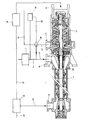
- Fluid composed of a liquid phase and a gaseous phase comes from a source 1 through a conduit 2.
- a conduit 3 coming from the outlet 4 of a turbine 5 of a turbomachine.
- This machine essentially comprises the turbine having the outlet 4 and an inlet 6 and a pump 7 having an inlet 8 and an outlet 9 and wedged on the same shaft 10 as the turbine 5.
- a detailed description of this turbomachine can be found in French patent 7823250 .
- a device 18 making it possible to adjust the quantities of liquid which go respectively to the conduit 11 and to a rejection conduit 17.
- the device 18 is controlled via a line 20 by a detector 19 which detects the gas contents of the fluid passing through the conduit 2.
- the mixture of fluid and liquid is sent under a pressure of between 10 and 100 bar, via a conduit 11, to the inlet 8 of the pump 7.
- the latter discharges it through the outlet 9 and through a conduit 12 into a separation apparatus 13, where the mixture, optionally after settling or centrifugation of the solid materials, is separated into a first stream going through the conduit 14, with compression in a pump 16 at a pressure between 20 and 250 bar, at the inlet 6 of the turbine 5 and in a second stream discharged through a conduit 15.
- the gas content of the first stream is less than 5% by volume.
- 60 m 3 / h of gas-free oil are sent to the turbine under a pressure of 100 bar.
- the turbomachine rotates at 6000 rpm.
- the pressure relief height in the turbine is 800 m.
- the expanded oil is mixed at 60 m 3 / h of crude oil having a GLR of 10.
- GLR represents the ratio of the volume of gas to the volume of liquid.
- the head of the pump is 150 m. Despite its high GLR, the crude can thus be pumped without difficulty.
Landscapes
- Engineering & Computer Science (AREA)
- Mechanical Engineering (AREA)
- General Engineering & Computer Science (AREA)
- Structures Of Non-Positive Displacement Pumps (AREA)
- Separation Using Semi-Permeable Membranes (AREA)
- Jet Pumps And Other Pumps (AREA)
Abstract
Installation comprenant une source (1), la sortie de la turbine débouchant dans un conduit mettant la source (1) en communication avec la pompe (7).Installation comprising a source (1), the outlet of the turbine opening into a conduit putting the source (1) in communication with the pump (7).
Description
La présente invention se rapporte aux procédés et aux installations pour faire circuler des fluides par pompage. Plus particulièrement l'invention vise des procédés et installations pour pomper des fluides composés d'au moins une phase liquide et d'au moins une phase gazeuse, cette dernière rendant le pompage très difficile.The present invention relates to methods and installations for circulating fluids by pumping. More particularly, the invention relates to methods and installations for pumping fluids composed of at least one liquid phase and at least one gaseous phase, the latter making pumping very difficult.
Au brevet français 2 470 878, on décrit déjà un procédé pour pomper du fluide composé d'une phase liquide et d'une phase gazeuse/qui consiste à envoyer du liquide sous pression à l'entrée de la turbine d'une turbomachine comprenant une pompe, ayant une entrée et une sortie, et une turbine,qui a une entrée et une sortie distinctes de celles de la pompe et qui est calée sur le même arbre que la pompe. Tout le liquide issu de la turbine est mélangé au fluide à faire passer dans la pompe, afin d'obtenir un effet d'éjection. Il est donc impératif, pour obtenir cet effet d'éjection, que l'énergie du liquide à la sortie de la turbine soit encore importante et notamment que l'énergie cinétique du liquide sortant de la turbine soit suffisante pour aspirer les fluides du puits vers la pompe. L'éjecteur ainsi constitué applique une élévation initiale de pression au fluide du puits. Il convient donc que le liquide sorte de la turbine en ayant également une certaine pression. Il en résulte que l'énergie du liquide n'est pas utilisée au mieux dans la turbine/puisqu'une partie de cette énergie est nécessaire pour une opération en aval. En outre, si mélanger tout le liquide au fluide est avantageux en vue de conférer au fluide la vitesse nécessaire pour le faire passer dans la pompe, cela a l'inconvénient que la pompe doit être prévue pour un grand débit et nécessite donc une puissance importante.In French Patent 2,470,878, there is already disclosed a method for pumping fluid composed of a liquid phase and a gas phase / of sending pressurized liquid to the inlet of the turbine of a turbomachine comprising a pump, having an inlet and an outlet, and a turbine, which has an inlet and an outlet separate from those of the pump and which is wedged on the same shaft as the pump. All the liquid from the turbine is mixed with the fluid to be passed through the pump, in order to obtain an ejection effect. It is therefore imperative, in order to obtain this ejection effect, that the energy of the liquid leaving the turbine is still large and in particular that the kinetic energy of the liquid leaving the turbine is sufficient to suck the fluids from the well towards the pump. The ejector thus formed applies an initial pressure increase to the fluid in the well. The liquid should therefore leave the turbine while also having a certain pressure. As a result, the energy of the liquid is not optimally used in the turbine / since part of this energy is necessary for a downstream operation. In addition, if mixing all the liquid with the fluid is advantageous in order to give the fluid the speed necessary to pass it through the pump, this has the disadvantage that the pump must be designed for a large flow rate and therefore requires a large power .
L'invention pallie ces inconvénients par un procédé pour pomper du fluide composé d'une phase liquide et d'une phase gazeuse qui permet de faire fonctionner la turbine dans les meilleures conditions et qui ne nécessite qu'une puissance aussi faible que possible pour le fonctionnement de la pompe.The invention overcomes these drawbacks by a method for pumping fluid composed of a liquid phase and a gaseous phase which makes it possible to operate the turbine under the best conditions and which requires only as little power as possible for the pump operation.
Le procédé suivant l'invention, consiste à ne mélanger au fluide qu'une partie du liquide représentant la proportion qui est nécessaire pour abaisser la teneur en gaz du mélange à une valeur inférieure à celle à partir de laquelle le mélange peut être pompé dans la pompe et à rejeter ou retourner le reste du liquide à l'entrée de la turbine.The method according to the invention consists in mixing with the fluid only a part of the liquid representing the proportion which is necessary to reduce the gas content of the mixture to a value lower than that from which the mixture can be pumped into the pump and reject or return the rest of the liquid to the turbine inlet.
Suivant l'invention, on ne cherche plus à faire jouer au liquide un rôle quelconque d'éjection. Le liquide sert de fluide d'alimentation de la turbine de la turbomachine, fournissant l'énergie nécessaire au fonctionnement de la pompe.Une partie du liquide sert aussi à diminuer la teneur en gaz du fluide et à la rendre ainsi acceptable pour que le mélange de fluide et de liquide puisse être pompé. Comme il passe aussi peu de liquide turbiné détendu que possible dans la pompe, celle-ci nécessite aussi peu de puissance que possible.According to the invention, there is no longer any attempt to make the liquid play any role of ejection. The liquid serves as the supply fluid for the turbine of the turbomachine, supplying the energy necessary for the operation of the pump. Part of the liquid also serves to reduce the gas content of the fluid and thus make it acceptable so that the mixture fluid and liquid can be pumped. Since as little expanded turbid liquid is passed through the pump as possible requires as little power as possible.
Avantageusement on détend complètement le liquide dans la turbine et on ne lui laisse pas non plus d'énergie cinétique. La turbine fonctionne ainsi dans les meilleures conditions.Advantageously, the liquid is completely expanded in the turbine and neither is it allowed kinetic energy. The turbine thus operates under the best conditions.
De préférence, on détecte la teneur en gaz du fluide et on modifie la proportion du liquide mélangé au fluide en fonction de la teneur en gaz détecte.Preferably, the gas content of the fluid is detected and the proportion of the liquid mixed with the fluid is modified as a function of the gas content detected.
En général, le rapport entre la quantité du liquide turbiné entrant dans le mélange et celle qui est rejetée peut varier entre 0 et 0,5 . In general, the ratio between the quantity of turbinated liquid entering the mixture and that which is discharged can vary between 0 and 0.5 .
Avantageusement, le débit de liquide turbiné mélangé au fluide, qui représente de 0 à 2 parties en volume pour 1 partie du fluide, est égal au débit de liquide, séparé sous forme d'un premier courant et représentant de 25 % à 65 % du volume du mélange, qui sort de la pompe.Advantageously, the flow rate of turbinated liquid mixed with the fluid, which represents from 0 to 2 parts by volume per 1 part of the fluid, is equal to the flow rate of liquid, separated in the form of a first stream and representing from 25% to 65% of the volume of the mixture, which leaves the pump.
L'invention vise aussi une installation de pompage comprenant une source de fluide et une turbomachine comprenant une pompe, ayant une entrée et une sortie, et une turbine qui est calée sur le même arbre que la pompe et qui a une entrée et une sortie, la sortie de la turbine débouchant dans un conduit mettant la source en communication avec la pompe. L'installation se caractérise par un conduit de rejet ou de retour communiquant avec la sortie de la turbine et par un dispositif permettant de régler les quantités de liquide provenant de la sortie de la turbine qui vont dans le conduit de rejet ou de retour et dans le conduit mettant la source en communication avec la pompe.The invention also relates to a pumping installation comprising a fluid source and a turbomachine comprising a pump, having an inlet and an outlet, and a turbine which is set on the same shaft as the pump and which has an inlet and an outlet, the outlet of the turbine opening into a conduit putting the source in communication with the pump. The installation is characterized by a rejection or return duct communicating with the outlet of the turbine and by a device making it possible to regulate the quantities of liquid coming from the outlet of the turbine which go into the rejection or return duct and into the conduit putting the source in communication with the pump.
Suivant une variante avantageuse, l'installation comprend un détecteur de la teneur en gaz du fluide et le dispositif permettant de régler les quantités de liquide est commandé par le détecteur par l'intermédiaire d'une ligne de commande en fonction des teneurs détectées.According to an advantageous variant, the installation comprises a detector of the gas content of the fluid and the device making it possible to adjust the quantities of liquid is controlled by the detector via a command line in function levels detected.
Avantageusement, l'installation comprend un appareillage de séparation d'un fluide constitué d'une phase gazeuse et d'une phase liquide en un premier courant plus riche en la phase liquide que le fluide et en un second courant, l'appareillage étant muni d'une entrée qui communique avec la sortie de la pompe et de deux sorties, dont l'une pour le premier courant communique avec l'entrée de la turbine.Advantageously, the installation comprises an apparatus for separating a fluid consisting of a gas phase and a liquid phase into a first stream richer in the liquid phase than the fluid and into a second stream, the apparatus being provided an input which communicates with the output of the pump and two outputs, one of which for the first current communicates with the input of the turbine.
De préférence, la pompe est telle que la courbe représentant la valeur de la courbure le long du squelette du profil d'une pale en fonction de l'absence curviligne le long de ce squelette, ait une pente dont la valeur croit progressivement depuis le bord d'attaque vers le bord de fuite de la pale, comme décrit au brevet français 7 536 774; la pompe a avantageusement les autres caractéristiques définies à ce brevet, mais la pompe pouvant avoir toute autre hydraulique adaptée spécialement aux écoulements diphasiques.Preferably, the pump is such that the curve representing the value of the curvature along the skeleton of the profile of a blade as a function of the curvilinear absence along this skeleton, has a slope whose value gradually increases from the edge of attack towards the trailing edge of the blade, as described in French patent 7,536,774; the pump advantageously has the other characteristics defined in this patent, but the pump can have any other hydraulics specially adapted to two-phase flows.
La figure unique du dessin annexé illustre l'invention.The single figure of the accompanying drawing illustrates the invention.
Du fluide composé d'une phase liquide et d'une phase gazeuse est issu d'une source 1 par un conduit 2. Dans le conduit 2 débouche un conduit 3 provenant de la sortie 4 d'une turbine 5 d'une turbomachine. Cette machine comporte essentiellement la turbine ayant la sortie 4 et une entrée 6 et une pompe 7 ayant une entrée 8 et une sortie 9 et calée sur le même arbre 10 que la turbine 5. On trouvera une description détaillée de cette turbomachine au brevet français 7823250.Fluid composed of a liquid phase and a gaseous phase comes from a
Sur la conduit 3 est monté un dispositif 18 permettant de régler les quantités de liquide qui vont respectivement vers le conduit 11 et vers un conduit de rejet 17. Le dispositif 18 est commandé par l'intermédiaire d'une ligne 20 par un détecteur 19 qui détecte les teneurs en gaz du fluide passant dans le conduit 2.On the pipe 3 is mounted a
Le mélange de fluide et de liquide est envoyé sous une pression comprise entre 10 et 100 bar, par un conduit 11, à l'entrée 8 de la pompe 7. Celle-ci le refoule par la sortie 9 et par un conduit 12 dans un appareillage de séparation 13, où le mélange, éventuellement après décantation ou centrifugation des matières solides, est séparé en un premier courant allant par le conduit 14, avec compression dans une pompe 16 sous une pression comprise entre 20 et 250 bar, à l'entrée 6 de la turbine 5 et en un second courant évacué par un conduit 15.The mixture of fluid and liquid is sent under a pressure of between 10 and 100 bar, via a
La teneur en gaz du premier courant est inférieure à 5 % en volume.The gas content of the first stream is less than 5% by volume.
L'exemple suivant illustre l'invention.The following example illustrates the invention.
On envoie dans la turbine 60 m3/h d'huile exempte de gaz sous une pression de 100 bar. La turbomachine tourne à 6000 t/min. La hauteur manométrique de détente dans la turbine est de 800 m. On mélange l'huile détendu à 60m 3/h d'un brut ayant un GLR de 10. GLR représente le rapport du volume de gaz au volume de liquide. La hauteur manométrique de la pompe est de 150 m. En dépit de son GLR élevé, le brut peut être ainsi pompé sans difficulté.60 m 3 / h of gas-free oil are sent to the turbine under a pressure of 100 bar. The turbomachine rotates at 6000 rpm. The pressure relief height in the turbine is 800 m. The expanded oil is mixed at 60 m 3 / h of crude oil having a GLR of 10. GLR represents the ratio of the volume of gas to the volume of liquid. The head of the pump is 150 m. Despite its high GLR, the crude can thus be pumped without difficulty.
Claims (11)
Applications Claiming Priority (2)
| Application Number | Priority Date | Filing Date | Title |
|---|---|---|---|
| FR8601763A FR2594183A1 (en) | 1986-02-10 | 1986-02-10 | METHOD AND INSTALLATION FOR CIRCULATING FLUIDS BY PUMPING |
| FR8601763 | 1986-02-10 |
Publications (2)
| Publication Number | Publication Date |
|---|---|
| EP0236166A1 true EP0236166A1 (en) | 1987-09-09 |
| EP0236166B1 EP0236166B1 (en) | 1990-10-03 |
Family
ID=9331956
Family Applications (1)
| Application Number | Title | Priority Date | Filing Date |
|---|---|---|---|
| EP87400158A Expired - Lifetime EP0236166B1 (en) | 1986-02-10 | 1987-01-23 | Process and installation for circulating fluids by pumping |
Country Status (7)
| Country | Link |
|---|---|
| US (1) | US4712984A (en) |
| EP (1) | EP0236166B1 (en) |
| JP (1) | JPS62191671A (en) |
| DE (1) | DE3765271D1 (en) |
| ES (1) | ES2018026B3 (en) |
| FR (1) | FR2594183A1 (en) |
| NO (1) | NO168965C (en) |
Cited By (3)
| Publication number | Priority date | Publication date | Assignee | Title |
|---|---|---|---|---|
| US4979880A (en) * | 1988-02-29 | 1990-12-25 | Shell Oil Company | Apparatus for pumping well effluents |
| EP0671563A1 (en) * | 1994-03-10 | 1995-09-13 | Weir Pumps Limited | Axial-flow pumps |
| US5755554A (en) * | 1995-12-22 | 1998-05-26 | Weir Pumps Limited | Multistage pumps and compressors |
Families Citing this family (11)
| Publication number | Priority date | Publication date | Assignee | Title |
|---|---|---|---|---|
| FR2680983B1 (en) * | 1991-09-10 | 1993-10-29 | Institut Francais Petrole | CONTINUOUS MIXER DEVICE, METHOD AND USE IN A PUMP INSTALLATION OF A HIGH VISCOSITY FLUID. |
| US5323823A (en) * | 1992-12-11 | 1994-06-28 | Roto Zip Tool Corporation | Wood router bit |
| FR2748532B1 (en) * | 1996-05-07 | 1999-07-16 | Inst Francais Du Petrole | POLYPHASIC AND CENTRIFUGAL PUMPING SYSTEM |
| FR2748533B1 (en) * | 1996-05-07 | 1999-07-23 | Inst Francais Du Petrole | POLYPHASIC AND CENTRIFUGAL PUMPING SYSTEM |
| US5863188A (en) * | 1996-07-12 | 1999-01-26 | Dosman; James A. | Fluid flow reducer |
| BR0103443A (en) * | 2001-08-21 | 2004-03-09 | Petroleo Brasileiro Sa | Multiphase Pumping System and Method |
| US20110223039A1 (en) * | 2010-03-15 | 2011-09-15 | General Electric Company | Pump assembly and method |
| NO337108B1 (en) * | 2012-08-14 | 2016-01-25 | Aker Subsea As | Multiphase pressure amplification pump |
| US9512700B2 (en) | 2014-11-13 | 2016-12-06 | General Electric Company | Subsea fluid processing system and an associated method thereof |
| CN107532470B (en) * | 2015-04-01 | 2019-10-18 | 沙特阿拉伯石油公司 | Fluid for oil gas application drives hybrid system |
| US10463990B2 (en) | 2015-12-14 | 2019-11-05 | General Electric Company | Multiphase pumping system with recuperative cooling |
Citations (6)
| Publication number | Priority date | Publication date | Assignee | Title |
|---|---|---|---|---|
| DE2554608A1 (en) * | 1975-02-06 | 1976-08-19 | Sundstrand Corp | BOREHOLE PUMP AND METHOD OF PUMPING FROM DEEP WELLS |
| US4035023A (en) * | 1975-07-15 | 1977-07-12 | Freeport Minerals Company | Apparatus and process for hydraulic mining |
| GB2014862A (en) * | 1978-02-24 | 1979-09-05 | Inst Francais Du Petrole | Methods of and apparatus for conveying diphasic fluids through pipes |
| FR2417057A1 (en) * | 1978-02-14 | 1979-09-07 | Inst Francais Du Petrole | METHOD AND DEVICE FOR TRANSPORTING BY PIPELINE A FLUID CONSISTING OF ESSENTIAL GAS MASS |
| US4233154A (en) * | 1978-12-29 | 1980-11-11 | Kobe, Inc. | Method for treating petroleum well pumping power fluid |
| FR2557643A1 (en) * | 1983-12-30 | 1985-07-05 | Inst Francais Du Petrole | DEVICE FOR SUPPLYING A DIPHASIC FLUID PUMP AND HYDROCARBON PRODUCTION PLANT COMPRISING SUCH A DEVICE |
Family Cites Families (8)
| Publication number | Priority date | Publication date | Assignee | Title |
|---|---|---|---|---|
| US975526A (en) * | 1910-09-15 | 1910-11-15 | Ernest K Hood | Propeller turbine-pump. |
| US1842961A (en) * | 1925-11-16 | 1932-01-26 | Anna M C Wechsberg | Locomotive feed water heater |
| DE1103687B (en) * | 1959-06-30 | 1961-03-30 | Siemens Ag | Gas turbine plant |
| US3194026A (en) * | 1963-10-24 | 1965-07-13 | Fleur Corp | Power-refrigeration system |
| US3420434A (en) * | 1966-12-30 | 1969-01-07 | Judson S Swearingen | Rotary compressors and systems employing same using compressor gas as seal gas |
| US4271664A (en) * | 1977-07-21 | 1981-06-09 | Hydragon Corporation | Turbine engine with exhaust gas recirculation |
| US4292011A (en) * | 1979-08-20 | 1981-09-29 | Kobe, Inc. | Turbo pump gas compressor |
| NL8001472A (en) * | 1980-03-12 | 1981-10-01 | Tno | INSTALLATION FOR HEAT RECOVERY ON COMBUSTION MACHINE. |
-
1986
- 1986-02-10 FR FR8601763A patent/FR2594183A1/en active Pending
-
1987
- 1987-01-23 ES ES87400158T patent/ES2018026B3/en not_active Expired - Lifetime
- 1987-01-23 EP EP87400158A patent/EP0236166B1/en not_active Expired - Lifetime
- 1987-01-23 DE DE8787400158T patent/DE3765271D1/en not_active Expired - Fee Related
- 1987-02-04 US US07/010,686 patent/US4712984A/en not_active Expired - Lifetime
- 1987-02-09 NO NO870493A patent/NO168965C/en unknown
- 1987-02-10 JP JP62027426A patent/JPS62191671A/en active Pending
Patent Citations (6)
| Publication number | Priority date | Publication date | Assignee | Title |
|---|---|---|---|---|
| DE2554608A1 (en) * | 1975-02-06 | 1976-08-19 | Sundstrand Corp | BOREHOLE PUMP AND METHOD OF PUMPING FROM DEEP WELLS |
| US4035023A (en) * | 1975-07-15 | 1977-07-12 | Freeport Minerals Company | Apparatus and process for hydraulic mining |
| FR2417057A1 (en) * | 1978-02-14 | 1979-09-07 | Inst Francais Du Petrole | METHOD AND DEVICE FOR TRANSPORTING BY PIPELINE A FLUID CONSISTING OF ESSENTIAL GAS MASS |
| GB2014862A (en) * | 1978-02-24 | 1979-09-05 | Inst Francais Du Petrole | Methods of and apparatus for conveying diphasic fluids through pipes |
| US4233154A (en) * | 1978-12-29 | 1980-11-11 | Kobe, Inc. | Method for treating petroleum well pumping power fluid |
| FR2557643A1 (en) * | 1983-12-30 | 1985-07-05 | Inst Francais Du Petrole | DEVICE FOR SUPPLYING A DIPHASIC FLUID PUMP AND HYDROCARBON PRODUCTION PLANT COMPRISING SUCH A DEVICE |
Non-Patent Citations (1)
| Title |
|---|
| SOVIET INVENTIONS ILLUSTRATED, Derwent Publications Ltd, Section Mechanical, Week D48, résumé no. 88902 D/48, Q56, 13 janvier 1982; & SU-A-808 699 (IVANO-FRANK OIL GAS) 28 février 1981 * |
Cited By (4)
| Publication number | Priority date | Publication date | Assignee | Title |
|---|---|---|---|---|
| US4979880A (en) * | 1988-02-29 | 1990-12-25 | Shell Oil Company | Apparatus for pumping well effluents |
| EP0671563A1 (en) * | 1994-03-10 | 1995-09-13 | Weir Pumps Limited | Axial-flow pumps |
| US5562405A (en) * | 1994-03-10 | 1996-10-08 | Weir Pumps Limited | Multistage axial flow pumps and compressors |
| US5755554A (en) * | 1995-12-22 | 1998-05-26 | Weir Pumps Limited | Multistage pumps and compressors |
Also Published As
| Publication number | Publication date |
|---|---|
| DE3765271D1 (en) | 1990-11-08 |
| NO168965C (en) | 1992-04-22 |
| NO870493L (en) | 1987-08-11 |
| ES2018026B3 (en) | 1991-03-16 |
| US4712984A (en) | 1987-12-15 |
| FR2594183A1 (en) | 1987-08-14 |
| JPS62191671A (en) | 1987-08-22 |
| NO870493D0 (en) | 1987-02-09 |
| NO168965B (en) | 1992-01-13 |
| EP0236166B1 (en) | 1990-10-03 |
Similar Documents
| Publication | Publication Date | Title |
|---|---|---|
| EP0236166B1 (en) | Process and installation for circulating fluids by pumping | |
| EP1861580B1 (en) | Pipe separator inlet | |
| US8092692B2 (en) | Apparatus and method for separating immiscible fluid components | |
| EP0107572B1 (en) | Device and method for the detection of the cavitation protection of a displacement pump | |
| EP2683458B1 (en) | Cyclonic flow separator | |
| EP1947385B1 (en) | Fuel injection device in a turbomachine | |
| WO2010116076A1 (en) | Ejector device for forming a pressurized mixture of liquid and gas, and use thereof | |
| FR2857650A1 (en) | NACELLE OR LAMINAR FLOW SURFACE FOR AN AIRCRAFT ENGINE | |
| EP0246943B1 (en) | Process and installation to cause circulation of fluids by pumping | |
| FR2478018A1 (en) | WATER JET PROPULSION DEVICE FOR OPERATING A BOAT | |
| FR2489705A1 (en) | SEPARATING DEVICE FOR DEGAZING FLUIDS | |
| CH705213B1 (en) | Pump comprising an axial balancing system. | |
| FR2518649A1 (en) | TWO-DIMENSIONAL, UNILATERAL IMPACT DIFFUSER AS AIR INLET FOR HIGH-PERFORMANCE AIRCRAFT PROPULSION TURBOJUSTER | |
| CA2158247C (en) | Polyphase pumping device with feedback loop | |
| US5128033A (en) | Oil separator | |
| EP0040129B1 (en) | High capacity oil recovery device for cleaning the surface of rough waters | |
| EP0058610B1 (en) | Method and installation for producing a high vacuum using a single-stage liquid-ring pump | |
| EP0098674B1 (en) | Method for the homogenization of liquid mixtures | |
| EP0140732A1 (en) | Device for picking up a polluting layer from the water surface | |
| EP1007838A1 (en) | Injector based induction device for motor vehicle fuel tank | |
| De Salis et al. | Exit oil production platforms | |
| LU83568A1 (en) | CONTINUOUS PROCESS FOR PRODUCING ENERGY WITHOUT CONSUMING FUEL | |
| FR2518488A2 (en) | Vessel for skimming oil from waste surface - uses integral hull extensions to scoop top layer of liquid into eye of separator pumps | |
| BE335514A (en) | ||
| OA17216A (en) | Cyclonic flow separator. |
Legal Events
| Date | Code | Title | Description |
|---|---|---|---|
| PUAI | Public reference made under article 153(3) epc to a published international application that has entered the european phase |
Free format text: ORIGINAL CODE: 0009012 |
|
| AK | Designated contracting states |
Kind code of ref document: A1 Designated state(s): DE ES FR GB IT NL |
|
| 17P | Request for examination filed |
Effective date: 19870916 |
|
| 17Q | First examination report despatched |
Effective date: 19880906 |
|
| ITF | It: translation for a ep patent filed | ||
| GRAA | (expected) grant |
Free format text: ORIGINAL CODE: 0009210 |
|
| AK | Designated contracting states |
Kind code of ref document: B1 Designated state(s): DE ES FR GB IT NL |
|
| GBT | Gb: translation of ep patent filed (gb section 77(6)(a)/1977) | ||
| REF | Corresponds to: |
Ref document number: 3765271 Country of ref document: DE Date of ref document: 19901108 |
|
| PLBE | No opposition filed within time limit |
Free format text: ORIGINAL CODE: 0009261 |
|
| STAA | Information on the status of an ep patent application or granted ep patent |
Free format text: STATUS: NO OPPOSITION FILED WITHIN TIME LIMIT |
|
| 26N | No opposition filed | ||
| ITTA | It: last paid annual fee | ||
| REG | Reference to a national code |
Ref country code: FR Ref legal event code: CD |
|
| REG | Reference to a national code |
Ref country code: FR Ref legal event code: CA |
|
| PGFP | Annual fee paid to national office [announced via postgrant information from national office to epo] |
Ref country code: DE Payment date: 19970205 Year of fee payment: 11 |
|
| PGFP | Annual fee paid to national office [announced via postgrant information from national office to epo] |
Ref country code: ES Payment date: 19980122 Year of fee payment: 12 |
|
| PGFP | Annual fee paid to national office [announced via postgrant information from national office to epo] |
Ref country code: NL Payment date: 19980127 Year of fee payment: 12 |
|
| PG25 | Lapsed in a contracting state [announced via postgrant information from national office to epo] |
Ref country code: DE Free format text: LAPSE BECAUSE OF NON-PAYMENT OF DUE FEES Effective date: 19981001 |
|
| PG25 | Lapsed in a contracting state [announced via postgrant information from national office to epo] |
Ref country code: ES Free format text: LAPSE BECAUSE OF EXPIRATION OF PROTECTION Effective date: 19990125 |
|
| PG25 | Lapsed in a contracting state [announced via postgrant information from national office to epo] |
Ref country code: NL Free format text: LAPSE BECAUSE OF NON-PAYMENT OF DUE FEES Effective date: 19990801 |
|
| REG | Reference to a national code |
Ref country code: FR Ref legal event code: TP |
|
| PGFP | Annual fee paid to national office [announced via postgrant information from national office to epo] |
Ref country code: GB Payment date: 20000331 Year of fee payment: 14 |
|
| REG | Reference to a national code |
Ref country code: FR Ref legal event code: CD |
|
| PG25 | Lapsed in a contracting state [announced via postgrant information from national office to epo] |
Ref country code: GB Free format text: LAPSE BECAUSE OF NON-PAYMENT OF DUE FEES Effective date: 20010123 |
|
| REG | Reference to a national code |
Ref country code: ES Ref legal event code: FD2A Effective date: 20010601 |
|
| GBPC | Gb: european patent ceased through non-payment of renewal fee |
Effective date: 20010123 |
|
| PG25 | Lapsed in a contracting state [announced via postgrant information from national office to epo] |
Ref country code: IT Free format text: LAPSE BECAUSE OF NON-PAYMENT OF DUE FEES;WARNING: LAPSES OF ITALIAN PATENTS WITH EFFECTIVE DATE BEFORE 2007 MAY HAVE OCCURRED AT ANY TIME BEFORE 2007. THE CORRECT EFFECTIVE DATE MAY BE DIFFERENT FROM THE ONE RECORDED. Effective date: 20050123 |
|
| PGFP | Annual fee paid to national office [announced via postgrant information from national office to epo] |
Ref country code: FR Payment date: 20060126 Year of fee payment: 20 |