EP0235938A2 - Solid fuel combustion apparatus - Google Patents
Solid fuel combustion apparatus Download PDFInfo
- Publication number
- EP0235938A2 EP0235938A2 EP87300831A EP87300831A EP0235938A2 EP 0235938 A2 EP0235938 A2 EP 0235938A2 EP 87300831 A EP87300831 A EP 87300831A EP 87300831 A EP87300831 A EP 87300831A EP 0235938 A2 EP0235938 A2 EP 0235938A2
- Authority
- EP
- European Patent Office
- Prior art keywords
- boiler
- conveyor
- air
- nozzles
- gas
- Prior art date
- Legal status (The legal status is an assumption and is not a legal conclusion. Google has not performed a legal analysis and makes no representation as to the accuracy of the status listed.)
- Withdrawn
Links
Images

Classifications
-
- F—MECHANICAL ENGINEERING; LIGHTING; HEATING; WEAPONS; BLASTING
- F23—COMBUSTION APPARATUS; COMBUSTION PROCESSES
- F23B—METHODS OR APPARATUS FOR COMBUSTION USING ONLY SOLID FUEL
- F23B1/00—Combustion apparatus using only lump fuel
- F23B1/16—Combustion apparatus using only lump fuel the combustion apparatus being modified according to the form of grate or other fuel support
- F23B1/22—Combustion apparatus using only lump fuel the combustion apparatus being modified according to the form of grate or other fuel support using travelling grate
-
- F—MECHANICAL ENGINEERING; LIGHTING; HEATING; WEAPONS; BLASTING
- F23—COMBUSTION APPARATUS; COMBUSTION PROCESSES
- F23C—METHODS OR APPARATUS FOR COMBUSTION USING FLUID FUEL OR SOLID FUEL SUSPENDED IN A CARRIER GAS OR AIR
- F23C1/00—Combustion apparatus specially adapted for combustion of two or more kinds of fuel simultaneously or alternately, at least one kind of fuel being either a fluid fuel or a solid fuel suspended in a carrier gas or air
-
- F—MECHANICAL ENGINEERING; LIGHTING; HEATING; WEAPONS; BLASTING
- F23—COMBUSTION APPARATUS; COMBUSTION PROCESSES
- F23J—REMOVAL OR TREATMENT OF COMBUSTION PRODUCTS OR COMBUSTION RESIDUES; FLUES
- F23J15/00—Arrangements of devices for treating smoke or fumes
- F23J15/06—Arrangements of devices for treating smoke or fumes of coolers
-
- F—MECHANICAL ENGINEERING; LIGHTING; HEATING; WEAPONS; BLASTING
- F23—COMBUSTION APPARATUS; COMBUSTION PROCESSES
- F23J—REMOVAL OR TREATMENT OF COMBUSTION PRODUCTS OR COMBUSTION RESIDUES; FLUES
- F23J7/00—Arrangement of devices for supplying chemicals to fire
-
- F—MECHANICAL ENGINEERING; LIGHTING; HEATING; WEAPONS; BLASTING
- F23—COMBUSTION APPARATUS; COMBUSTION PROCESSES
- F23L—SUPPLYING AIR OR NON-COMBUSTIBLE LIQUIDS OR GASES TO COMBUSTION APPARATUS IN GENERAL ; VALVES OR DAMPERS SPECIALLY ADAPTED FOR CONTROLLING AIR SUPPLY OR DRAUGHT IN COMBUSTION APPARATUS; INDUCING DRAUGHT IN COMBUSTION APPARATUS; TOPS FOR CHIMNEYS OR VENTILATING SHAFTS; TERMINALS FOR FLUES
- F23L15/00—Heating of air supplied for combustion
-
- F—MECHANICAL ENGINEERING; LIGHTING; HEATING; WEAPONS; BLASTING
- F23—COMBUSTION APPARATUS; COMBUSTION PROCESSES
- F23L—SUPPLYING AIR OR NON-COMBUSTIBLE LIQUIDS OR GASES TO COMBUSTION APPARATUS IN GENERAL ; VALVES OR DAMPERS SPECIALLY ADAPTED FOR CONTROLLING AIR SUPPLY OR DRAUGHT IN COMBUSTION APPARATUS; INDUCING DRAUGHT IN COMBUSTION APPARATUS; TOPS FOR CHIMNEYS OR VENTILATING SHAFTS; TERMINALS FOR FLUES
- F23L9/00—Passages or apertures for delivering secondary air for completing combustion of fuel
- F23L9/02—Passages or apertures for delivering secondary air for completing combustion of fuel by discharging the air above the fire
-
- F—MECHANICAL ENGINEERING; LIGHTING; HEATING; WEAPONS; BLASTING
- F23—COMBUSTION APPARATUS; COMBUSTION PROCESSES
- F23L—SUPPLYING AIR OR NON-COMBUSTIBLE LIQUIDS OR GASES TO COMBUSTION APPARATUS IN GENERAL ; VALVES OR DAMPERS SPECIALLY ADAPTED FOR CONTROLLING AIR SUPPLY OR DRAUGHT IN COMBUSTION APPARATUS; INDUCING DRAUGHT IN COMBUSTION APPARATUS; TOPS FOR CHIMNEYS OR VENTILATING SHAFTS; TERMINALS FOR FLUES
- F23L9/00—Passages or apertures for delivering secondary air for completing combustion of fuel
- F23L9/04—Passages or apertures for delivering secondary air for completing combustion of fuel by discharging the air beyond the fire, i.e. nearer the smoke outlet
-
- Y—GENERAL TAGGING OF NEW TECHNOLOGICAL DEVELOPMENTS; GENERAL TAGGING OF CROSS-SECTIONAL TECHNOLOGIES SPANNING OVER SEVERAL SECTIONS OF THE IPC; TECHNICAL SUBJECTS COVERED BY FORMER USPC CROSS-REFERENCE ART COLLECTIONS [XRACs] AND DIGESTS
- Y02—TECHNOLOGIES OR APPLICATIONS FOR MITIGATION OR ADAPTATION AGAINST CLIMATE CHANGE
- Y02E—REDUCTION OF GREENHOUSE GAS [GHG] EMISSIONS, RELATED TO ENERGY GENERATION, TRANSMISSION OR DISTRIBUTION
- Y02E20/00—Combustion technologies with mitigation potential
- Y02E20/34—Indirect CO2mitigation, i.e. by acting on non CO2directly related matters of the process, e.g. pre-heating or heat recovery
Definitions
- THIS INVENTION concerns a boiler in which a bed of solid fuel is carried continuously or intermittently on a moving conveyor in one direction through a combustion chamber, the fuel being hopper-fed at a controlled rate to the inlet or upstream end of the conveyor.
- the conveyor In a boiler of this kind the conveyor consists of an endless line of fire bars motor driven through the combustion chamber by a pair of chains. Usually, a supply of combustion air is provided between the upper and lower strands of the conveyor, and combustion takes place above the fuel bed so that the fuel is fully combusted by the time it reaches the downstream end of the upper strand. A flow control gate determines the rate of introduction of fuel at the upstream end of the conveyor.
- Boilers of this kind are capable of achieving high efficiency combustion of coal but it is likely to be less efficient when burning certain alternative kinds of solid fuel such as refuse derived fuel and waste derived fuel, in pelleted form.
- the inherent calorific value of such alternative fuels is usually less than that of coal.
- An object of the present invention is to provide a boiler adapted to achieve high efficiency combustion when supplied with alternative kinds of solid fuel.
- a boiler in which a bed of solid fuel is carried on a moving conveyor in one direction through a combustion chamber, characterised by an air or other gas injection nozzle disposed above the conveyor adjacent the downstream or output end thereof and connected to a supply of air or other gas to direct a stream thereof towards the upstream or inlet end thereof such that the air stream passes over the fuel in counter-current with the gaseous products of combustion to enhance combustion of the bed of fuel on the conveyor.
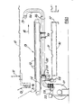
- a boiler casing l0 encloses a combustion chamber a part of whose wall is indicated at ll, in a generally horizontal cylindrical form.
- a chain grate conveyor consists of a continuous series of fire bars l2 carried along an upper conveying strand l3 by chains l4 which are motor driven to carry a bed of solid fuel supplied from a feed hopper l5, through the combustion chamber ll in one direction from left to right in Fig. l.
- a control gate l6 is adjustable to determine the rate of input of fuel into the boiler. Air for combustion is introduced between the upper and lower strands of the conveyor.
- the system is designed such that substantially complete combustion will have taken place by the time the bed of fuel has travelled throughout the length of the boiler so that only ash remains to be deposited from the upper strand l3 into an outlet chute l7. Gaseous combustion products pass in the direction of arrow l8 to the atmosphere via a stack (not shown).
- An air injection nozzle l9 is located above the upper strand l3 of the conveyor adjacent the downstream or output end thereof.
- the nozzle is fed via pipe 20 made of alloy steel or similar material, with a supply of air from a fan 2l situated outside the boiler casing l0.
- a pair of dampers 22 and 23 control the flow of air into pipe 20.
- the section of pipe 20 between nozzle l9 and an airtight rotary connector 24 is supported in bearings 25 to be rotatable as indicated by arrow 26 so that the nozzle l9 may be moved from its operative position as illustrated, through approximately 90° to an inoperative position below the upper and lower strands of the conveyor.
- Lever 27 and counter-weight 28 are used to select the rotational position of pipe 20.
- damper 23 which may be operated manually or automatically in accordance with the conditions prevailing within the combustion chamber.
- the air supply from fan 2l may be discontinued by closing damper 22, and the pipe 20 may be rotated to bring nozzle l9 to its inoperative position below the conveyor. In this condition the boiler will operate in the conventional manner without the counterflow air stream, since complete combustion of coal or certain other fuels may not require this additional air.
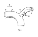
- the pipe 20 is vented off upstream of nozzle l9 into a tube 30 extending generally in the opposite direction to that of nozzle l9 and terminating in a nozzle 3l directing air longitudinally along the boiler chamber in the direction of arrow l8 and a pair of additional nozzles 32 directing air tangentially.
- the fan 2l is designed to provide sufficient volume of air to permit the necessary air flow from nozzle l9 to be maintained whilst providing an approximately equivalent volume of air flowing in tube 30 and distributed substantially evenly through nozzles 3l and 32.
- the effect is to distribute the air flow evenly across the boiler chamber at the downstream end thereof.
- the hot gases in this downstream part of the boiler during operation are evenly distributed across the so-called "wet back" of the boiler, which in turn increases the heat transfer to the latter, and there is also a substantial cooling of the exhaust gases thus solidifying silicates and other molten in suspension solids before they enter the usual second pass gas exit tubes of the boiler. Solidifying of these suspended gas constituents substantially reduces their deposition and thus build-up on the boiler walls and gas exit tube walls during passage therethrough.
- the additional nozzles 3l and 32 provide a balanced cooling effect whilst producing a vectored turbulence for the gases leaving the boiler chamber.
- Fig. 3 where like parts are afforded like reference numerals, there is shown a further alternative arrangement in which two parallel tubes 40 and 4l pass one above the other or side by side beneath the conveyor throughout the length of the boiler from fan 2l.
- reverse air injection nozzle 42 is fed from pipe 40 whilst forward air injection nozzle 43 is fed from pipe 4l.
- an inner smaller bore pipe 44 having its outlet nozzle concentric with nozzle 42 may be used to deliver combustible liquids or gases to flow through the boiler in the reverse direction along with the reverse air.
- an inner smaller bore pipe 45 within pipe 4l may carry coolant liquor or gas to the point of exit of nozzle 43.
- dampers for pipes 40 and 4l are shown schematically at 46 and 47 respectively.
- a hopper 48 is provided to deliver to pipe 40 additional materials such as magnesia dust.
- the pipe assembly 40, 4l may be pivoted into an inoperative position by way of rotary connection 49, if required, or alternatively maintained in a fixed position whilst supplies of liquid or gaseous materials are simply discontinued by means of dampers 46 and 47.
- the incoming air in its passage to nozzles l9, 3l and 32 may be otherwise preheated by indirect heat exchange with the exhaust gases from the boiler or by some other means.
- the entry positions for all pipes may be other than at the upstream end of the boiler, any convenient entry positions being selected for convenience provided that nozzles l9, 3l and 32 or nozzles 42 and 43 can be located correctly.
Abstract
Description
- THIS INVENTION concerns a boiler in which a bed of solid fuel is carried continuously or intermittently on a moving conveyor in one direction through a combustion chamber, the fuel being hopper-fed at a controlled rate to the inlet or upstream end of the conveyor.
- In a boiler of this kind the conveyor consists of an endless line of fire bars motor driven through the combustion chamber by a pair of chains. Usually, a supply of combustion air is provided between the upper and lower strands of the conveyor, and combustion takes place above the fuel bed so that the fuel is fully combusted by the time it reaches the downstream end of the upper strand. A flow control gate determines the rate of introduction of fuel at the upstream end of the conveyor.
- Boilers of this kind are capable of achieving high efficiency combustion of coal but it is likely to be less efficient when burning certain alternative kinds of solid fuel such as refuse derived fuel and waste derived fuel, in pelleted form. The inherent calorific value of such alternative fuels is usually less than that of coal.
- An object of the present invention is to provide a boiler adapted to achieve high efficiency combustion when supplied with alternative kinds of solid fuel.
- According to the present invention there is provided a boiler in which a bed of solid fuel is carried on a moving conveyor in one direction through a combustion chamber, characterised by an air or other gas injection nozzle disposed above the conveyor adjacent the downstream or output end thereof and connected to a supply of air or other gas to direct a stream thereof towards the upstream or inlet end thereof such that the air stream passes over the fuel in counter-current with the gaseous products of combustion to enhance combustion of the bed of fuel on the conveyor.
- An embodiment of the invention will now be described, by way of example only, with reference to the accompanying drawings in which:-
- Fig. l is a schematic illustration of the principal parts of a boiler made in accordance with the invention;
- Fig. 2 is an enlarged elevation of a modified form of one of said parts.
- and Fig. 3 is a schematic perspective view of the further modified form of the invention.
- A boiler casing l0 encloses a combustion chamber a part of whose wall is indicated at ll, in a generally horizontal cylindrical form. A chain grate conveyor consists of a continuous series of fire bars l2 carried along an upper conveying strand l3 by chains l4 which are motor driven to carry a bed of solid fuel supplied from a feed hopper l5, through the combustion chamber ll in one direction from left to right in Fig. l. A control gate l6 is adjustable to determine the rate of input of fuel into the boiler. Air for combustion is introduced between the upper and lower strands of the conveyor.
- The system is designed such that substantially complete combustion will have taken place by the time the bed of fuel has travelled throughout the length of the boiler so that only ash remains to be deposited from the upper strand l3 into an outlet chute l7. Gaseous combustion products pass in the direction of arrow l8 to the atmosphere via a stack (not shown).
- An air injection nozzle l9 is located above the upper strand l3 of the conveyor adjacent the downstream or output end thereof. The nozzle is fed via
pipe 20 made of alloy steel or similar material, with a supply of air from a fan 2l situated outside the boiler casing l0. A pair ofdampers pipe 20. The section ofpipe 20 between nozzle l9 and an airtight rotary connector 24 is supported inbearings 25 to be rotatable as indicated by arrow 26 so that the nozzle l9 may be moved from its operative position as illustrated, through approximately 90° to an inoperative position below the upper and lower strands of the conveyor. Lever 27 andcounter-weight 28 are used to select the rotational position ofpipe 20. - In use, with the boiler operating on a solid fuel such as refuse derived fuel or waste derived fuel, with or without a proportion of coal dust to enhance its calorific value or even with coal, and in order to ensure complete combustion of the fuel, further air is introduced above the upper strand of the conveyor, via nozzle l9. Thus a stream of air is directed along the combustion chamber towards the upstream end thereof, that is in counter-current with the gaseous products of combustion travelling in the direction of arrow l8. This air stream creates turbulence within the boiler and thus thorough mixing of liberated combustion gases to achieve high efficiency combustion of the fuel. In its passage to the nozzle l9 the air from fan 2l flows along
pipe 20 in the base of the combustion chamber so that the pipe acts as a heat exchanger to pre-heat the air before introduction. - In addition to the air supplied by fan 2l, additional constituents may be aspirated into the heated air flow to control the emission of noxious gases such as dioxins which may not be completely destroyed during the thermal process within the boiler. The flow of air and other constituents is controlled by
damper 23 which may be operated manually or automatically in accordance with the conditions prevailing within the combustion chamber. - If the boiler alternatively is supplied with coal, the air supply from fan 2l may be discontinued by closing
damper 22, and thepipe 20 may be rotated to bring nozzle l9 to its inoperative position below the conveyor. In this condition the boiler will operate in the conventional manner without the counterflow air stream, since complete combustion of coal or certain other fuels may not require this additional air. - In addition to improving the combustion and thus energy efficiency of the boiler, it is known that some alternative fuels when combusted create gases with a high dioxin content so that, conventionally, the combustion gases must be disposed of in a controlled and contained manner. With the present invention, the dioxin content in the exhausted gases is considerably reduced as a result of the enhanced combustion above the fuel bed.
- In a further embodiment as depicted in Fig. 2, the
pipe 20 is vented off upstream of nozzle l9 into atube 30 extending generally in the opposite direction to that of nozzle l9 and terminating in a nozzle 3l directing air longitudinally along the boiler chamber in the direction of arrow l8 and a pair ofadditional nozzles 32 directing air tangentially. - The fan 2l is designed to provide sufficient volume of air to permit the necessary air flow from nozzle l9 to be maintained whilst providing an approximately equivalent volume of air flowing in
tube 30 and distributed substantially evenly throughnozzles 3l and 32. The effect is to distribute the air flow evenly across the boiler chamber at the downstream end thereof. As a result of the air distribution the hot gases in this downstream part of the boiler during operation are evenly distributed across the so-called "wet back" of the boiler, which in turn increases the heat transfer to the latter, and there is also a substantial cooling of the exhaust gases thus solidifying silicates and other molten in suspension solids before they enter the usual second pass gas exit tubes of the boiler. Solidifying of these suspended gas constituents substantially reduces their deposition and thus build-up on the boiler walls and gas exit tube walls during passage therethrough. - Therefore the
additional nozzles 3l and 32 provide a balanced cooling effect whilst producing a vectored turbulence for the gases leaving the boiler chamber. - Referring now to Fig. 3 where like parts are afforded like reference numerals, there is shown a further alternative arrangement in which two
parallel tubes 40 and 4l pass one above the other or side by side beneath the conveyor throughout the length of the boiler from fan 2l. In this case reverseair injection nozzle 42 is fed frompipe 40 whilst forwardair injection nozzle 43 is fed from pipe 4l. Withinpipe 40 an innersmaller bore pipe 44 having its outlet nozzle concentric withnozzle 42 may be used to deliver combustible liquids or gases to flow through the boiler in the reverse direction along with the reverse air. Similarly, an innersmaller bore pipe 45 within pipe 4l may carry coolant liquor or gas to the point of exit ofnozzle 43. - In this embodiment, dampers for
pipes 40 and 4l are shown schematically at 46 and 47 respectively. - A
hopper 48 is provided to deliver to pipe 40 additional materials such as magnesia dust. - In the embodiment of Fig. 3 the
pipe assembly 40, 4l may be pivoted into an inoperative position by way ofrotary connection 49, if required, or alternatively maintained in a fixed position whilst supplies of liquid or gaseous materials are simply discontinued by means ofdampers 46 and 47. - It is not intended to limit the invention to the above examples only, many variations, such as might readily occur to one skilled in the art, being possible without departing from the scope of the invention as defined herein. For example, the incoming air in its passage to nozzles l9, 3l and 32 may be otherwise preheated by indirect heat exchange with the exhaust gases from the boiler or by some other means.
- In all embodiments the entry positions for all pipes may be other than at the upstream end of the boiler, any convenient entry positions being selected for convenience provided that nozzles l9, 3l and 32 or
nozzles
Claims (10)
Applications Claiming Priority (4)
| Application Number | Priority Date | Filing Date | Title |
|---|---|---|---|
| GB8602435 | 1986-01-31 | ||
| GB868602435A GB8602435D0 (en) | 1986-01-31 | 1986-01-31 | Boiler |
| GB8618621 | 1986-07-30 | ||
| GB868618621A GB8618621D0 (en) | 1986-01-31 | 1986-07-30 | Boiler |
Publications (2)
| Publication Number | Publication Date |
|---|---|
| EP0235938A2 true EP0235938A2 (en) | 1987-09-09 |
| EP0235938A3 EP0235938A3 (en) | 1988-09-14 |
Family
ID=26290304
Family Applications (1)
| Application Number | Title | Priority Date | Filing Date |
|---|---|---|---|
| EP87300831A Withdrawn EP0235938A3 (en) | 1986-01-31 | 1987-01-30 | Solid fuel combustion apparatus |
Country Status (2)
| Country | Link |
|---|---|
| EP (1) | EP0235938A3 (en) |
| GB (1) | GB2186065A (en) |
Families Citing this family (1)
| Publication number | Priority date | Publication date | Assignee | Title |
|---|---|---|---|---|
| TW221462B (en) * | 1991-06-28 | 1994-03-01 | Stein Atkinson Strody Ltd |
Citations (9)
| Publication number | Priority date | Publication date | Assignee | Title |
|---|---|---|---|---|
| BE422028A (en) * | ||||
| DE262374C (en) * | ||||
| GB134244A (en) * | 1918-06-05 | 1919-11-06 | Frank Ernest Plumb | Improvements in or relating to Positive Forced Draught Travelling Chain Grate Furnaces. |
| GB539559A (en) * | 1940-04-25 | 1941-09-16 | Brighton Hove & Worthing Gas C | Improvements in or relating to boiler furnaces |
| GB1190932A (en) * | 1966-05-24 | 1970-05-06 | Edwin Danks And Company Oldbur | Improvements in Shell-Type Boiler Firing Equipment |
| US4162686A (en) * | 1977-10-17 | 1979-07-31 | North American Manufacturing Company | Industrial boiler utilizing multiple fuels and having reduced particulate emission and method of combustion |
| DE2930301A1 (en) * | 1979-07-26 | 1981-03-12 | Wim Ing.(grad.) 7900 Ulm Johnen | Liq. and solid fuel combustion system - uses liq. fuel flame to ignite solid, with solid only burned when plant is up to temp. |
| JPS59185908A (en) * | 1983-04-05 | 1984-10-22 | Hitachi Zosen Corp | Desulfurization and denitrification device of flue tube and smoke tube boiler |
| US4624192A (en) * | 1986-03-20 | 1986-11-25 | Mansfield Carbon Products | Fluidized bed combuster process |
Family Cites Families (2)
| Publication number | Priority date | Publication date | Assignee | Title |
|---|---|---|---|---|
| GB436708A (en) * | 1935-02-27 | 1935-10-16 | Int Comb Ltd | Improvements in boiler furnaces |
| GB644241A (en) * | 1948-07-13 | 1950-10-04 | Babcock & Wilcox Dampfkesselwe | Improvements in or relating to combustion apparatus |
-
1987
- 1987-01-29 GB GB08702013A patent/GB2186065A/en not_active Withdrawn
- 1987-01-30 EP EP87300831A patent/EP0235938A3/en not_active Withdrawn
Patent Citations (9)
| Publication number | Priority date | Publication date | Assignee | Title |
|---|---|---|---|---|
| BE422028A (en) * | ||||
| DE262374C (en) * | ||||
| GB134244A (en) * | 1918-06-05 | 1919-11-06 | Frank Ernest Plumb | Improvements in or relating to Positive Forced Draught Travelling Chain Grate Furnaces. |
| GB539559A (en) * | 1940-04-25 | 1941-09-16 | Brighton Hove & Worthing Gas C | Improvements in or relating to boiler furnaces |
| GB1190932A (en) * | 1966-05-24 | 1970-05-06 | Edwin Danks And Company Oldbur | Improvements in Shell-Type Boiler Firing Equipment |
| US4162686A (en) * | 1977-10-17 | 1979-07-31 | North American Manufacturing Company | Industrial boiler utilizing multiple fuels and having reduced particulate emission and method of combustion |
| DE2930301A1 (en) * | 1979-07-26 | 1981-03-12 | Wim Ing.(grad.) 7900 Ulm Johnen | Liq. and solid fuel combustion system - uses liq. fuel flame to ignite solid, with solid only burned when plant is up to temp. |
| JPS59185908A (en) * | 1983-04-05 | 1984-10-22 | Hitachi Zosen Corp | Desulfurization and denitrification device of flue tube and smoke tube boiler |
| US4624192A (en) * | 1986-03-20 | 1986-11-25 | Mansfield Carbon Products | Fluidized bed combuster process |
Non-Patent Citations (1)
| Title |
|---|
| PATENT ABSTRACTS OF JAPAN, vol. 9, no. 46 (M-360)[1769], 27th February 1985; & JP-A-59 185 908 (HITACHI ZOSEN K.K.) 22-10-1984 * |
Also Published As
| Publication number | Publication date |
|---|---|
| EP0235938A3 (en) | 1988-09-14 |
| GB2186065A (en) | 1987-08-05 |
| GB8702013D0 (en) | 1987-03-04 |
Similar Documents
| Publication | Publication Date | Title |
|---|---|---|
| US4311103A (en) | Incineration system for sewage sludge | |
| US6532880B2 (en) | Method and apparatus for drying and incineration of sewage sludge | |
| SE519605C2 (en) | Solid fuel device and method | |
| JPS5971917A (en) | Thermal oxidizer and its operating method | |
| CZ20023557A3 (en) | Process and apparatus for burning solid fuels and waste | |
| CN105276574A (en) | Furnace system with internal flue gas recirculation | |
| US4616572A (en) | Biomass incinerator | |
| US4934931A (en) | Cyclonic combustion device with sorbent injection | |
| CN207514894U (en) | the gasification combustion system of complex mixed fuel | |
| US4840130A (en) | Waste disposal system | |
| JPS63204004A (en) | Furnace | |
| GB2139331A (en) | Pulverising drying and transporting apparatus for pulverised fuel | |
| CA1314766C (en) | Acid gas control process and apparatus for waste fired incinerators | |
| HU209806B (en) | Method and apparatus for introducing additives into cupola furnace | |
| EP0235938A2 (en) | Solid fuel combustion apparatus | |
| US4635568A (en) | Furnace afterburner | |
| US5127345A (en) | Combustion apparatus and combustion control method therefor | |
| JPS63172808A (en) | Melting furnace of swirl air type | |
| JPS60159511A (en) | Method and device for burning ash forming solid | |
| CZ283961B6 (en) | Flue boiler | |
| JPH054565B2 (en) | ||
| EP0443850A2 (en) | Fluidized bed combustion apparatus for burning wastes | |
| JP2000111025A (en) | Secondary combustion furnace | |
| US3888632A (en) | Combustion chamber | |
| KR19980070746A (en) | Temperature control method and waste treatment device among waste treatment devices by heat |
Legal Events
| Date | Code | Title | Description |
|---|---|---|---|
| PUAI | Public reference made under article 153(3) epc to a published international application that has entered the european phase |
Free format text: ORIGINAL CODE: 0009012 |
|
| AK | Designated contracting states |
Kind code of ref document: A2 Designated state(s): AT BE CH DE ES FR GB GR IT LI LU NL SE |
|
| PUAL | Search report despatched |
Free format text: ORIGINAL CODE: 0009013 |
|
| AK | Designated contracting states |
Kind code of ref document: A3 Designated state(s): AT BE CH DE ES FR GB GR IT LI LU NL SE |
|
| 17P | Request for examination filed |
Effective date: 19890302 |
|
| 17Q | First examination report despatched |
Effective date: 19900108 |
|
| STAA | Information on the status of an ep patent application or granted ep patent |
Free format text: STATUS: THE APPLICATION IS DEEMED TO BE WITHDRAWN |
|
| 18D | Application deemed to be withdrawn |
Effective date: 19900519 |
|
| RIN1 | Information on inventor provided before grant (corrected) |
Inventor name: PORTER, DAVID |