EP0235844B1 - Schutzgitter für den Lufteinlauf einer Turbomaschine - Google Patents
Schutzgitter für den Lufteinlauf einer Turbomaschine Download PDFInfo
- Publication number
- EP0235844B1 EP0235844B1 EP87200206A EP87200206A EP0235844B1 EP 0235844 B1 EP0235844 B1 EP 0235844B1 EP 87200206 A EP87200206 A EP 87200206A EP 87200206 A EP87200206 A EP 87200206A EP 0235844 B1 EP0235844 B1 EP 0235844B1
- Authority
- EP
- European Patent Office
- Prior art keywords
- turbo
- guard
- engine
- elements
- parts
- Prior art date
- Legal status (The legal status is an assumption and is not a legal conclusion. Google has not performed a legal analysis and makes no representation as to the accuracy of the status listed.)
- Expired - Lifetime
Links
- 238000004904 shortening Methods 0.000 claims abstract description 6
- 239000004033 plastic Substances 0.000 claims description 12
- 229920003023 plastic Polymers 0.000 claims description 12
- 241001465754 Metazoa Species 0.000 claims description 11
- 239000011230 binding agent Substances 0.000 claims description 6
- 229910052799 carbon Inorganic materials 0.000 claims description 6
- OKTJSMMVPCPJKN-UHFFFAOYSA-N Carbon Chemical compound [C] OKTJSMMVPCPJKN-UHFFFAOYSA-N 0.000 claims description 5
- 239000002184 metal Substances 0.000 claims description 5
- 239000000463 material Substances 0.000 claims description 4
- 238000004804 winding Methods 0.000 claims description 2
- 230000000717 retained effect Effects 0.000 claims 4
- 238000010276 construction Methods 0.000 abstract description 8
- 241000531908 Aramides Species 0.000 description 2
- 241000271566 Aves Species 0.000 description 2
- 229920003235 aromatic polyamide Polymers 0.000 description 2
- 239000000835 fiber Substances 0.000 description 2
- PQHRHABVSWOYPG-UHFFFAOYSA-N 2,9-dioxatricyclo[8.2.2.24,7]hexadeca-1(13),4,6,10(14),11,15-hexaene-3,8-dione Chemical compound O1C(=O)C(C=C2)=CC=C2C(=O)OC2=CC=C1C=C2 PQHRHABVSWOYPG-UHFFFAOYSA-N 0.000 description 1
- WRDNCFQZLUCIRH-UHFFFAOYSA-N 4-(7-azabicyclo[2.2.1]hepta-1,3,5-triene-7-carbonyl)benzamide Chemical compound C1=CC(C(=O)N)=CC=C1C(=O)N1C2=CC=C1C=C2 WRDNCFQZLUCIRH-UHFFFAOYSA-N 0.000 description 1
- 229920000271 Kevlar® Polymers 0.000 description 1
- 239000004952 Polyamide Substances 0.000 description 1
- 230000001419 dependent effect Effects 0.000 description 1
- 230000002349 favourable effect Effects 0.000 description 1
- 239000004761 kevlar Substances 0.000 description 1
- 238000004519 manufacturing process Methods 0.000 description 1
- 229920002647 polyamide Polymers 0.000 description 1
- 229920000642 polymer Polymers 0.000 description 1
- 230000003014 reinforcing effect Effects 0.000 description 1
Images


Classifications
-
- F—MECHANICAL ENGINEERING; LIGHTING; HEATING; WEAPONS; BLASTING
- F02—COMBUSTION ENGINES; HOT-GAS OR COMBUSTION-PRODUCT ENGINE PLANTS
- F02C—GAS-TURBINE PLANTS; AIR INTAKES FOR JET-PROPULSION PLANTS; CONTROLLING FUEL SUPPLY IN AIR-BREATHING JET-PROPULSION PLANTS
- F02C7/00—Features, components parts, details or accessories, not provided for in, or of interest apart form groups F02C1/00 - F02C6/00; Air intakes for jet-propulsion plants
- F02C7/04—Air intakes for gas-turbine plants or jet-propulsion plants
- F02C7/05—Air intakes for gas-turbine plants or jet-propulsion plants having provisions for obviating the penetration of damaging objects or particles
- F02C7/055—Air intakes for gas-turbine plants or jet-propulsion plants having provisions for obviating the penetration of damaging objects or particles with intake grids, screens or guards
-
- B—PERFORMING OPERATIONS; TRANSPORTING
- B64—AIRCRAFT; AVIATION; COSMONAUTICS
- B64D—EQUIPMENT FOR FITTING IN OR TO AIRCRAFT; FLIGHT SUITS; PARACHUTES; ARRANGEMENT OR MOUNTING OF POWER PLANTS OR PROPULSION TRANSMISSIONS IN AIRCRAFT
- B64D33/00—Arrangement in aircraft of power plant parts or auxiliaries not otherwise provided for
- B64D33/02—Arrangement in aircraft of power plant parts or auxiliaries not otherwise provided for of combustion air intakes
- B64D2033/022—Arrangement in aircraft of power plant parts or auxiliaries not otherwise provided for of combustion air intakes comprising bird or foreign object protections
Definitions
- the invention relates to a turbo-engine guard for mounting on the air inlet side of a turbo-engine, particularly for aeroplanes, said turbo-engine guard comprising guard elements having an aerodynamic shape being chosen such that elements or element parts do not exert disturbing influence on the air stream flowing along said elements to the turbo-engine to be protected.
- Such a turbo-engine guard preventing damage to a turbo-engine by animals, in particular birds, entering the engine parts via the air inlet of turbo-engines at a high velocity with the air stream is known from US-A-2.717.685 or GB-A-1.137.470.
- guard elements of the abovementioned type animals in particular large birds, can be entirely prevented from coming into contact with the turbo-engine without the guard elements uacceptably influencing the air supply as a result. It is obvious that the animal's body may be torn to pieces by the guard element, but said parts show no noticeable, or only limited damage.
- the guard elements can very expediently be situated in more than one plane.
- the guard can be kept under a tension so that these elements after collision with an animal can substantially return to their original shape and state. This will, for example, be possible to take place by providing the elements or parts of elements with a specified spring force in the interior of the elements or outside thereof.
- guard elements are made up, partially or completely, of fibrous and/or foam-like and/or wire-like elements with a stretch and thickness as well as elasticity such that after collision with a live animal, these elements can substantially return to their original shape and state.
- This construction can be made, partially or completely, particularly of a plastic, preferably a plastic having properties of plastics of the poly-p-phenyleneterephthalamide type or stronger materials which are also sufficiently stretchable and elastic.
- Suitable fibrous, film-like or wire-like components for guard elements of a poly-p-phenyleneterephthalate polyamide type are those of aramide plastics such as “kevlar R” or “Twaran R ". Guard elements constructed of these plastics have the advantage that they are very lightweight and at the same time strong and sufficiently elastic and stretchable.
- Guards constructed completely or partially of the abovementioned plastics or corresponding materials at the same time have the advantage that, should one element nevertheless break as a result of a collision, the broken parts will remain firmly in place on a fastening point, and the end which came loose need not cause any serious damage, in spite of possible drag along the compressor blades, in view of the fact that the plastics of which the elements are constructed are nevertheless subject to wear despite the high tensile strength, so that only small parts of such an element can come loose and can pass the remainder of the turbo-engine virtually without causing any damage.
- the guard elements can also be constructed of metal, carbon fibres or other strong materials.
- a broken element may cause damage when a part of this element comes into contact with the rotating part of the turbo-engine, so that it is advisable in this case that in the event of breakage, the parts can be pulled away from the area of action of the air stream flowing in by means of a member or construction, mounted inside or outside the air inlet and/or inside or outside the element in question, or alternatively these parts are pulled in.
- the aerodynamically shaped elements which will preferably possess a slightly elongate or drop-shaped or arched drop-shaped cross-section, are twistable to a greater or lesser degree about their longitudinal axis; as a result the position of the element, or parts thereof can adjust to the direction of the air stream in a manner such that the air stream is disturbed as little as possible.
- a turbo-engine guard according to the invention is preferably mounted so as to be detachable and replaceable.
- Figure 1 shows a turbo-engine with an air inlet 1 through which the air required for this power source can flow in.
- the air inlet (see figures 1 and 2) is provided with a set 2 of guard elements 3.
- the elements 3 are arranged, with respect to each other, in the direction of flow of the entering air, in a helical pattern which may or may not be variable; in which each element is always positioned uniformly staggered behind the preceding element, in which case the side from which the air flows in can be considered the front side.
- These elements 3 are or may be entirely or partially constructed of aramide and possess, as a whole or in part, a section according to figure 3, although a section according to figure 4 can also be used expediently.
- the elements are or may also be constructed of filaments of fibres 4 which are held together by a binder possibly based on a polymer.
- a binder possibly based on a polymer.
- films can also be assembled in this way.
- the binder can be a plastic binder 5 or some other type of binder, provided that these are resistant to temperatures of at least +150°C and at least to temperatures of -50°C and sufficiently elastic.
- the fibres or filaments can consist of carbon or metal or plastics.
- Figure 3 shows a specified favourable aerodynamic section and figure 4 shows another section of the elements 3.
- Figure 5 shows a view of a guard element being twistable about its longitudinal axis with the fastening points 7 and 7'. It is obvious that the parts 3a, 3b and 3c of element 3 are aerodynamically shaped. In this context and in the other sections of the description aerodynamic means that the guard elements possess a design such that these elements do not exert any unacceptable disturbing influence on the air stream which flows along said elements to the engine to be protected during the operation of the engine.
- an element is constructed such that in the event of breakage, seen in longitudinal direction, it breaks at an essentially predetermined position 8.
- the two ends 7, 7' can be rounded because they are taken up in the casing construction of the air inlet, outside the air stream.
- the parts 3a and 3b of the element shown in figure 5 can rotate independently of each other, due to the middle part 3c which, can be made thinner if required, and possibly more or less round, along with and adapting to the angle of incidence of the air stream which enters the turbo power source and passes the elements 3.
- each imaganery section of the element which folds within the air stream should preferably be chosen such that each imaganery section of the element which folds within the air stream, can adapt as well as possible to the local angle of incidence of this air stream.
- the most expedient dimension of the aerodynamically shaped elements is dependent upon various factors such as the type of the turbo-engine and the requirements set.
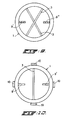
- Figure 9 shows a view of parts 9' and 9" which have resulted through breakage of an element 3, the part 9' after the breakage having been shortened by assuming, for example, a spiral shape.
- figure 10 shows a wind-up member 10 under spring tension which can pull a part 9' out of the air stream after breakage.
- wind-up member 10 can also hold an unbroken element 3 under a specified pretension.
- This embodiment is particularly suitable for elements 3 made of metal.
- the guard elements 3 as a whole or in part, can possess a cross-section as shown in figures 3 and 4 or a combination thereof.
Landscapes
- Engineering & Computer Science (AREA)
- Chemical & Material Sciences (AREA)
- Combustion & Propulsion (AREA)
- Mechanical Engineering (AREA)
- General Engineering & Computer Science (AREA)
- Aviation & Aerospace Engineering (AREA)
- Structures Of Non-Positive Displacement Pumps (AREA)
- Supercharger (AREA)
- Other Air-Conditioning Systems (AREA)
- Air Filters, Heat-Exchange Apparatuses, And Housings Of Air-Conditioning Units (AREA)
Claims (11)
- Turbomotorschutz (2) zum Montieren an der Lufteinlaß-(1)-Seite eines Turbomotors, insbesondere für Flugzeuge, wobei der Turbomotorschutz Schutzelemente (3) mit einer aerodynamischen Form aufweist, die derart gewählt ist, daß Elemente oder Elementteile keinen störenden Einfluß auf den Luftstrom ausüben, der entlang der Elemente zu dem zu schützenden Turbomotor fließt,
dadurch gekennzeichnet
daß die Schutzelemente (3) in einem spiralförmigen Muster montiert sind. - Turbomotorschutz nach Anspruch 1, dadurch gekennzeichnet, daß die Schutzelemente (3) entlang spindelförmiger Linien montiert sind.
- Turbomotorschutz nach Anspruch 1 oder 2, dadurch gekennzeichnet, daß die Elemente (3) mit einem schwächeren Teil versehen sind, der zulaßt, daß sie im wesentlichen bei einer vorbestimmten Position brechen.
- Turbomotorschutz nach irgendeinem der Ansprüche 1 bis 3, dadurch gekennzeichnet, daß der Schutz ein Zurückziehelement (10) aufweist zum Zurückziehen eines an einem Ende noch zurückgehaltenen Teils eines gebrochenen Schutzelements (3) im Fall eines Bruchs des gleichen, weg von dem einfließenden Luftstrombereich einer Wirkung zu einem derartigen Ausmaß, daß die vorstehende Länge des gebrochenen Teils geringer ist als der Abstand zwischen den drehenden Teilen des Turbomotors, wenn er im Betrieb ist, und dem Teil, an dem der gebrochene Teil zurückgehalten ist, wobei das Zurückziehelement innerhalb oder außerhalb des Lufteinlasses und/oder innerhalb oder außerhalb des betreffenden Elements montiert ist.
- Turbomotorschutz nach irgendeinem der Ansprüche 1 bis 4, dadurch gekennzeichnet, daß das Schutzelement (3) mit inneren Zugspannungen versehen ist, die ein Zurückziehen eines an einem Ende noch gehaltenen gebrochenen Teils eines Schutzelements im Falle eines Brechens des gleichen veranlaßt, so daß ein resultierender gebrochener Teil einer zweckmäßigen Verkürzung ausgesetzt ist, und zwar auf eine Länge, die geringer ist als der Abstand zwischen den rotierenden Teilen des Turbomotors, wenn er im Betrieb ist, und dem Ort, an dem dieser gebrochene resultierende Teil zurückgehalten ist.
- Turbomotorschutz nach Anspruch 5, dadurch gekennzeichnet, daß die zweckmäßige Verkürzung durch eine Federkraft erhalten wird, die in diese Teile eingeführt ist.
- Turbomotorschutz nach Anspruch 5 oder 6, dadurch gekennzeichnet, daß die zweckmäßig Verkürzung zu einer spiralförmigen Windung eines freien Endes des gebrochenen Teils führt.
- Turbomotorschutz nach irgendeinem der Ansprüche 1 bis 7, dadurch gekennzeichnet, daß die Schutzelemente (3) vollständig oder teilweise aus Elementen aufgebaut sind, die aus faserigen, filmähnlichen und drahtähnlichen Elementen ausgewählt sind, und zwar mit einer Dehnbarkeit und einer Dicke und auch einer Elastizität derart, daß dieses Elemente nach einer Kollision mit einem lebende Tier im wesentlichen in ihre Ursprungsform und ihren Ursprungszustand zurückkehren.
- Turbomotorschutz nach irgendeinem der Ansprüche 1 bis 8, dadurch gekennzeichnet, daß das Material eines Schutzelements (3) mindestens teilweise aus einem Plastikmaterial ausgewählt ist, das Eigenschaften des Poly-p-phenylenterepthalamid-Typs besitzt, aus Karbonfasern, Metall und Teilen, die durch einen Kleber zusammengehalten werden, der eine Temperatur zwischen -50 °C und + 150 °C aushält.
- Turbomotorschutz nach irgendeinem der Ansprüche 1 bis 9, dadurch gekennzeichnet, daß die Schutzelemente (3) oder Teile davon um ihre Längsachse verdrehbar sind.
- Turbomotorschutz nach irgendeinem der Ansprüche 1 bis 10, dadurch gekennzeichnet, daß die Schutzelemente einen Querschnitt haben, der aus einer Tropfenform, einer gewölbten Tropfenform und verlängerten abgerundeten Querschnitten (Fig. 3, 4, 6, 7, 8) ausgewählt ist.
Priority Applications (1)
| Application Number | Priority Date | Filing Date | Title |
|---|---|---|---|
| AT87200206T ATE67277T1 (de) | 1986-02-12 | 1987-02-11 | Schutzgitter fuer den lufteinlauf einer turbomaschine. |
Applications Claiming Priority (2)
| Application Number | Priority Date | Filing Date | Title |
|---|---|---|---|
| NL8600351 | 1986-02-12 | ||
| NL8600351A NL8600351A (nl) | 1986-02-12 | 1986-02-12 | Turbinemotorbescherming. |
Publications (2)
| Publication Number | Publication Date |
|---|---|
| EP0235844A1 EP0235844A1 (de) | 1987-09-09 |
| EP0235844B1 true EP0235844B1 (de) | 1991-09-11 |
Family
ID=19847567
Family Applications (1)
| Application Number | Title | Priority Date | Filing Date |
|---|---|---|---|
| EP87200206A Expired - Lifetime EP0235844B1 (de) | 1986-02-12 | 1987-02-11 | Schutzgitter für den Lufteinlauf einer Turbomaschine |
Country Status (8)
| Country | Link |
|---|---|
| US (1) | US4833879A (de) |
| EP (1) | EP0235844B1 (de) |
| JP (1) | JPS62247133A (de) |
| AT (1) | ATE67277T1 (de) |
| CA (1) | CA1307672C (de) |
| DE (1) | DE3772796D1 (de) |
| NL (1) | NL8600351A (de) |
| SU (1) | SU1658825A3 (de) |
Cited By (1)
| Publication number | Priority date | Publication date | Assignee | Title |
|---|---|---|---|---|
| DE102009029540A1 (de) | 2009-09-17 | 2011-03-24 | Matthias Wiegand | Vorrichtung zum Schützen von Turbotriebwerken gegen Einschlag von Fremdkörpern |
Families Citing this family (23)
| Publication number | Priority date | Publication date | Assignee | Title |
|---|---|---|---|---|
| US5143321A (en) * | 1991-09-09 | 1992-09-01 | Thomas H. Jackson | Folding protective cover for turbo-engines |
| USD433029S (en) * | 1999-06-10 | 2000-10-31 | Ross Eidson | Jet engine intake deflection guard |
| EP1237641B1 (de) * | 1999-11-23 | 2015-09-09 | Marina Ellen Marinella Pavlatos | Motor mit rotierend befestigtem schutz |
| US8876930B2 (en) * | 1999-11-23 | 2014-11-04 | Marina Ellen Marinella Pavlatos | Single/multiple guard(s)/cap(s) and/or screen(s) with engine attached chamber/manifold particle collector |
| DE10122305A1 (de) * | 2001-05-08 | 2002-11-14 | Joachim Henkler | Ansauggitter |
| FR2840029B1 (fr) * | 2002-05-27 | 2004-08-13 | Mbdam | Systeme d'obturation pour un orifice d'un conduit, en particulier pour un orifice d'une voie d'introduction d'air dans la chambre de combustion d'un statoreacteur |
| RU2362029C1 (ru) * | 2008-03-04 | 2009-07-20 | Государственное образовательное учреждение высшего профессионального образования "Ульяновский государственный технический университет" | Устройство для защиты турбореактивного двигателя от попадания посторонних предметов |
| RU2366822C1 (ru) * | 2008-03-25 | 2009-09-10 | Государственное образовательное учреждение высшего профессионального образования "Ульяновский государственный технический университет" | Устройство для защиты турбореактивного двигателя от попадания посторонних предметов |
| US7988088B2 (en) * | 2008-06-05 | 2011-08-02 | Konstantinovskiy Alexandr | Tubular air transport vehicle |
| RU2375262C1 (ru) * | 2008-06-24 | 2009-12-10 | Государственное образовательное учреждение высшего профессионального образования "Ульяновский государственный технический университет" | Устройство для защиты турбореактивного двигателя от попадания посторонних предметов |
| US7971827B2 (en) * | 2009-04-27 | 2011-07-05 | Barrientos Ernesto D | Bird collision prevention device for an aircraft |
| US8117820B1 (en) | 2009-05-26 | 2012-02-21 | Briscoe Edward V | Jet engine intake deflector system |
| US8756909B2 (en) * | 2009-07-22 | 2014-06-24 | The CtFoT Group LLC | Aircraft engine protection device |
| USD631420S1 (en) | 2009-08-12 | 2011-01-25 | Joseph Locklear | Airplane turbine engine shield |
| US8052083B1 (en) * | 2009-09-17 | 2011-11-08 | John Patrick Moran | Bird deflector and air replacement system technical field |
| US7803204B1 (en) | 2009-10-19 | 2010-09-28 | Mladinich Julius C | Foreign object deflector for jet engine |
| US20110146294A1 (en) * | 2009-12-22 | 2011-06-23 | Rubin Townsend | Airplane engine deflector systems |
| US7963094B1 (en) * | 2010-01-19 | 2011-06-21 | Cupolo Francis J | Fragmentor for bird ingestible gas turbine engine |
| USD621852S1 (en) | 2010-01-26 | 2010-08-17 | John Zunik | Aircraft engine safety shield |
| ES2648229T3 (es) * | 2012-09-27 | 2017-12-29 | Shield Aerodynamics Llc | Escudo de defensa ambiental |
| WO2014135942A1 (en) * | 2013-03-06 | 2014-09-12 | Bombardier Inc. | Apparatus for protecting aircraft components against foreign object damage |
| US9550581B2 (en) * | 2015-02-26 | 2017-01-24 | Pratt & Whitney Canada Corp. | Gas turbine engine cover |
| CN117326074B (zh) * | 2023-11-13 | 2026-01-16 | 中国直升机设计研究所 | 一种内嵌折叠式发动机进气道防护装置及其控制方法 |
Family Cites Families (8)
| Publication number | Priority date | Publication date | Assignee | Title |
|---|---|---|---|---|
| GB626571A (en) * | 1945-08-17 | 1949-07-18 | Westinghouse Electric Int Co | Improvements in or relating to gas turbine power plants |
| GB663194A (en) * | 1948-12-09 | 1951-12-19 | Power Jets Res & Dev Ltd | Improvements relating to compressors and engines embodying the same |
| US2747685A (en) * | 1954-01-12 | 1956-05-29 | United Aircraft Corp | Inlet screen segment |
| US2931460A (en) * | 1957-12-12 | 1960-04-05 | Orenda Engines Ltd | Debris guard |
| US3121545A (en) * | 1962-01-10 | 1964-02-18 | John J Moss | Rotary deflector for aircraft engine intakes |
| GB1137479A (en) * | 1966-02-28 | 1968-12-18 | Mini Of Technology | Foreign body guards for aircraft |
| DE1296021B (de) * | 1966-09-19 | 1969-05-22 | Secretary Technology Brit | Vorrichtung zum Schutz eines Lufteinlasses gegen Fremdkoerper, insbesondere bei Flugzeugstrahltriebwerken |
| US4149689A (en) * | 1976-08-18 | 1979-04-17 | Mcdonald John | Protective screen for jet-engine intake |
-
1986
- 1986-02-12 NL NL8600351A patent/NL8600351A/nl not_active Application Discontinuation
-
1987
- 1987-02-11 DE DE8787200206T patent/DE3772796D1/de not_active Expired - Fee Related
- 1987-02-11 EP EP87200206A patent/EP0235844B1/de not_active Expired - Lifetime
- 1987-02-11 AT AT87200206T patent/ATE67277T1/de active
- 1987-02-12 US US07/014,019 patent/US4833879A/en not_active Expired - Fee Related
- 1987-02-12 SU SU874202019A patent/SU1658825A3/ru active
- 1987-02-12 JP JP62030632A patent/JPS62247133A/ja active Pending
- 1987-02-12 CA CA000529553A patent/CA1307672C/en not_active Expired - Lifetime
Cited By (2)
| Publication number | Priority date | Publication date | Assignee | Title |
|---|---|---|---|---|
| DE102009029540A1 (de) | 2009-09-17 | 2011-03-24 | Matthias Wiegand | Vorrichtung zum Schützen von Turbotriebwerken gegen Einschlag von Fremdkörpern |
| DE102009029540B4 (de) * | 2009-09-17 | 2020-02-13 | Matthias Wiegand | Vorrichtung zum Schützen von Turbotriebwerken gegen Einschlag von Fremdkörpern |
Also Published As
| Publication number | Publication date |
|---|---|
| EP0235844A1 (de) | 1987-09-09 |
| NL8600351A (nl) | 1987-09-01 |
| ATE67277T1 (de) | 1991-09-15 |
| JPS62247133A (ja) | 1987-10-28 |
| SU1658825A3 (ru) | 1991-06-23 |
| US4833879A (en) | 1989-05-30 |
| DE3772796D1 (de) | 1991-10-17 |
| CA1307672C (en) | 1992-09-22 |
Similar Documents
| Publication | Publication Date | Title |
|---|---|---|
| EP0235844B1 (de) | Schutzgitter für den Lufteinlauf einer Turbomaschine | |
| DE69901600T2 (de) | Autonomes flexibles aerodynamisches schhneidelement mit angepasstem kopf | |
| US2465936A (en) | Emergency arresting device for moving objects | |
| EP0935805A1 (de) | Geflochtener elektrozaun | |
| US4377370A (en) | Safety device for a rotating element of a turbine engine | |
| US5411224A (en) | Guard for jet engine | |
| US4138157A (en) | Energy absorbing seat belt webbing | |
| US4957094A (en) | Compound archery bow with non-stretch bowstring and eccentrics for securing same | |
| US3456917A (en) | Bladed rotor,particularly for a compressor | |
| US3426981A (en) | Foreign body guards | |
| DE3722420C2 (de) | ||
| US4552121A (en) | Archery sights | |
| WO2010126734A1 (en) | Bird collision prevention device for an aircraft | |
| CN102089473A (zh) | 固定装置 | |
| GB1576171A (en) | Rotary cutting assembly | |
| US5143380A (en) | Broadhead for an arrow | |
| GB2503997A (en) | A cutter, cutter head assembly and rotary cutting machine | |
| AU562140B2 (en) | Fishing hook protector | |
| US3343354A (en) | Flexible lawn mower blade | |
| DE60120842T2 (de) | Zerstörbares verschlussstück für die montageöffnung von bläserschaufeln bei einem bläsertriebwerk | |
| US5405102A (en) | Foldaway aircraft air vane | |
| DE3711764C2 (de) | ||
| JP6105203B2 (ja) | 芳香族ポリアミドからフィラメント糸を製造する方法 | |
| KR102183880B1 (ko) | 항공기 엔진 보호 기구 | |
| DE1296021B (de) | Vorrichtung zum Schutz eines Lufteinlasses gegen Fremdkoerper, insbesondere bei Flugzeugstrahltriebwerken |
Legal Events
| Date | Code | Title | Description |
|---|---|---|---|
| PUAI | Public reference made under article 153(3) epc to a published international application that has entered the european phase |
Free format text: ORIGINAL CODE: 0009012 |
|
| AK | Designated contracting states |
Kind code of ref document: A1 Designated state(s): AT BE CH DE ES FR GB GR IT LI LU NL SE |
|
| 17P | Request for examination filed |
Effective date: 19870803 |
|
| 17Q | First examination report despatched |
Effective date: 19881202 |
|
| GRAA | (expected) grant |
Free format text: ORIGINAL CODE: 0009210 |
|
| AK | Designated contracting states |
Kind code of ref document: B1 Designated state(s): AT BE CH DE ES FR GB GR IT LI LU NL SE |
|
| PG25 | Lapsed in a contracting state [announced via postgrant information from national office to epo] |
Ref country code: BE Effective date: 19910911 Ref country code: IT Free format text: LAPSE BECAUSE OF FAILURE TO SUBMIT A TRANSLATION OF THE DESCRIPTION OR TO PAY THE FEE WITHIN THE PRE;WARNING: LAPSES OF ITALIAN PATENTS WITH EFFECTIVE DATE BEFORE 2007 MAY HAVE OCCURRED AT ANY TIME BEFORE 2007. THE CORRECT EFFECTIVE DATE MAY BE DIFFERENT FROM THE ONE RECORDED.SCRIBED TIME-LIMIT Effective date: 19910911 Ref country code: AT Effective date: 19910911 Ref country code: LI Effective date: 19910911 Ref country code: SE Effective date: 19910911 Ref country code: GR Free format text: LAPSE BECAUSE OF FAILURE TO SUBMIT A TRANSLATION OF THE DESCRIPTION OR TO PAY THE FEE WITHIN THE PRESCRIBED TIME-LIMIT Effective date: 19910911 Ref country code: CH Effective date: 19910911 |
|
| REF | Corresponds to: |
Ref document number: 67277 Country of ref document: AT Date of ref document: 19910915 Kind code of ref document: T |
|
| REF | Corresponds to: |
Ref document number: 3772796 Country of ref document: DE Date of ref document: 19911017 |
|
| PG25 | Lapsed in a contracting state [announced via postgrant information from national office to epo] |
Ref country code: ES Free format text: LAPSE BECAUSE OF FAILURE TO SUBMIT A TRANSLATION OF THE DESCRIPTION OR TO PAY THE FEE WITHIN THE PRESCRIBED TIME-LIMIT Effective date: 19911222 |
|
| REG | Reference to a national code |
Ref country code: CH Ref legal event code: PL |
|
| ET | Fr: translation filed | ||
| PG25 | Lapsed in a contracting state [announced via postgrant information from national office to epo] |
Ref country code: LU Free format text: LAPSE BECAUSE OF NON-PAYMENT OF DUE FEES Effective date: 19920229 |
|
| PLBE | No opposition filed within time limit |
Free format text: ORIGINAL CODE: 0009261 |
|
| STAA | Information on the status of an ep patent application or granted ep patent |
Free format text: STATUS: NO OPPOSITION FILED WITHIN TIME LIMIT |
|
| 26N | No opposition filed | ||
| PGFP | Annual fee paid to national office [announced via postgrant information from national office to epo] |
Ref country code: GB Payment date: 19930104 Year of fee payment: 7 |
|
| PGFP | Annual fee paid to national office [announced via postgrant information from national office to epo] |
Ref country code: FR Payment date: 19930108 Year of fee payment: 7 |
|
| PGFP | Annual fee paid to national office [announced via postgrant information from national office to epo] |
Ref country code: NL Payment date: 19930228 Year of fee payment: 7 |
|
| PGFP | Annual fee paid to national office [announced via postgrant information from national office to epo] |
Ref country code: DE Payment date: 19930323 Year of fee payment: 7 |
|
| PG25 | Lapsed in a contracting state [announced via postgrant information from national office to epo] |
Ref country code: GB Effective date: 19940211 |
|
| PG25 | Lapsed in a contracting state [announced via postgrant information from national office to epo] |
Ref country code: NL Effective date: 19940901 |
|
| GBPC | Gb: european patent ceased through non-payment of renewal fee |
Effective date: 19940211 |
|
| NLV4 | Nl: lapsed or anulled due to non-payment of the annual fee | ||
| PG25 | Lapsed in a contracting state [announced via postgrant information from national office to epo] |
Ref country code: FR Effective date: 19941031 |
|
| PG25 | Lapsed in a contracting state [announced via postgrant information from national office to epo] |
Ref country code: DE Effective date: 19941101 |
|
| REG | Reference to a national code |
Ref country code: FR Ref legal event code: ST |