EP0235631A2 - Method of forming halftone screen - Google Patents
Method of forming halftone screen Download PDFInfo
- Publication number
- EP0235631A2 EP0235631A2 EP87101934A EP87101934A EP0235631A2 EP 0235631 A2 EP0235631 A2 EP 0235631A2 EP 87101934 A EP87101934 A EP 87101934A EP 87101934 A EP87101934 A EP 87101934A EP 0235631 A2 EP0235631 A2 EP 0235631A2
- Authority
- EP
- European Patent Office
- Prior art keywords
- halftone screen
- scanning lines
- halftone
- screen
- scanning
- Prior art date
- Legal status (The legal status is an assumption and is not a legal conclusion. Google has not performed a legal analysis and makes no representation as to the accuracy of the status listed.)
- Granted
Links
Images


Classifications
-
- H—ELECTRICITY
- H04—ELECTRIC COMMUNICATION TECHNIQUE
- H04N—PICTORIAL COMMUNICATION, e.g. TELEVISION
- H04N1/00—Scanning, transmission or reproduction of documents or the like, e.g. facsimile transmission; Details thereof
- H04N1/40—Picture signal circuits
- H04N1/405—Halftoning, i.e. converting the picture signal of a continuous-tone original into a corresponding signal showing only two levels
- H04N1/4055—Halftoning, i.e. converting the picture signal of a continuous-tone original into a corresponding signal showing only two levels producing a clustered dots or a size modulated halftone pattern
- H04N1/4058—Halftoning, i.e. converting the picture signal of a continuous-tone original into a corresponding signal showing only two levels producing a clustered dots or a size modulated halftone pattern with details for producing a halftone screen at an oblique angle
-
- Y—GENERAL TAGGING OF NEW TECHNOLOGICAL DEVELOPMENTS; GENERAL TAGGING OF CROSS-SECTIONAL TECHNOLOGIES SPANNING OVER SEVERAL SECTIONS OF THE IPC; TECHNICAL SUBJECTS COVERED BY FORMER USPC CROSS-REFERENCE ART COLLECTIONS [XRACs] AND DIGESTS
- Y10—TECHNICAL SUBJECTS COVERED BY FORMER USPC
- Y10S—TECHNICAL SUBJECTS COVERED BY FORMER USPC CROSS-REFERENCE ART COLLECTIONS [XRACs] AND DIGESTS
- Y10S359/00—Optical: systems and elements
- Y10S359/90—Methods
Definitions
- the present invention relates a method of forming a halftone screen, and more particularly to a halftone screen forming method which is capable, when producing a reproduceable halftone dot image by superposing an image signal generated by scanning an original bearing a continuous-tone image on an electrically generated halftone screen signal, of eliminating a periodic pattern in the halftone dot image by forming each of the dots of the halftone screen produced by the above halftone screen signal with an integral number of scanning lines commensurate with the screen angle of the halftone screen.
- image scanning reading and recording apparatus are widely used in the field of printing and graphic art for electrically processing image information of originals to produce original film plates with a view to simplifying the entire process and improving the quality of printed images.
- the image scanning reading and recording apparatus are basically constructed of an input unit, a control unit, and an output unit.
- an original delivered to an image reader is scanned by a laser beam or the like, and image information of the original is converted to an electric signal representative of different intensities of reflected laser light.
- the photoelectrically converted image information is then processed in the control unit for tone correction, outline emphasis, or the like according to platemaking conditions.
- the image information which is processed by the control unit is thereafter fed to the output unit in which it is converted again to a light signal such as a laser beam.
- the light signal is applied to a recording medium such as a photosensitive material to record the image thereon.
- the image on the recording medium is then developed by a developing device, after which the recording medium is used as an original film plate.
- an original to be printed or reproduced bears a continuous-tone image such as a photograph or a painting
- a continuous-tone image is converted to a halftone dot image which is composed of closely spaced dots of different sizes according to gradations of density of the image.
- One method of breaking up a continuous-tone image into halftone dots is to apply a light signal commensurate with the continuous-tone image to a film through a contact screen having a vignetted dot pattern.
- the aforesaid image scanning reading and recording apparatus employ a process for electrically forming a halftone screen corresponding to such a contact screen.
- FIG. l of the accompanying drawings shows a basic periodic portion 2 of a halftone screen which is electrically formed.
- the halftone screen is composed of repetitions of one pattern, and the minimum unit of the halftone screen is the basic periodic portion 2.
- the basic periodic portion 2 is constructed of eight scanning lines Sl through S8 arranged side by side in the direction Y. Each of the scanning lines Sl through S8 forms an element of the basic periodic portion 2 with an inherent voltage signal that varies in the recording direction X.
- the voltages of the scanning lines Sl, S2, S4, S5 passing through points A through D in a dot 4 are high, and the scanning line S3 passing through a point E is low.
- the voltages of the sanning lines Sl through S5 are selected to become gradually lower from the points A through D to the point E.
- the voltage signals or halftone screen signals of the scanning lines Sl through S8 may be produced by superposing a plurality of alternating voltage signals of triangular waveform which have different periods, and slightly shifting the phases of those voltage signals.
- the halftone screens When converting a multicolor image or the like to dots, it is necessary to generate a plurality of halftone screens and superpose halftone dot images produced respectively by those halftone screens. In order to prevent a moire pattern from being produced when the halftone screens are superposed, the halftone screens are formed while they are rotated a prescribed angle ⁇ with respect to the recording direction X.
- the basic periodic portion 2 is periodically produced frequently enough to cover a scanned region of the oridinal, for thereby producing a halftone screen.
- the halftone screen signals constituting the halftone screen are superposed on an image signal that has optically been read from the original by the input unit of the image scanning reading and recording apparatus, so that a halftone-dot image is formed on a film plate.
- the halftone screen signals can sufficiently accurately represent the gradations of the halftone screen in the case where the width of each of the scanning lines Sl through S8 of the basic periodic portion 2 is sufficiently smaller than the width of the basic periodic portion 2 in the direction Y and hence the voltages of the halftone screen signals continuously vary in the direction Y.
- the width of each of the scanning lines Sl through S8 is not negligible with respect to the width of the basic periodic portion 2 in the direction Y, the voltages of the halftone screen signals vary in a step-like discrete manner between the adjacent scnanning lines Sl through S8.
- the voltages at the points A through D may gradually vary in the scanning lines Sl, S2, S4, S5, and such a voltage variation may cause a periodic pattern to be produced in the basic periodic portion 2. Should such a periodic pattern be large enough to be visually conspicuous, an unsightly pattern, other than the gradations of the original, would be introduced into the halftone dot image as with a moire patteren.
- Another object of the present invention is to provide a method of forming a halftone screen in producing a halftone dot image by superposing image information produced by scanning an original on the halftone screen composed of a plurality of scanning lines constituted by electrically generated halftone screen signals and arranged side by side in a direction normal to a scanning direction in which the scanning lines extend, the method comprising the steps of forming each of dots of the halftone screen with an integral number of scanning lines commensurate with a screen angle of the halftone screen, and equalizing the halftone screen signals in level at mutually corresponding areas in the respective dots.
- Still another object of the present invention is to provide a method of forming a halftone screen, wherein the number of scanning lines is selected so as to pass through areas of the dots where the halftone screen signals are of a maximum level.
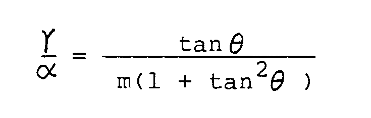
- a further object of the present invention is to provide a method of forming a halftone screen, wherein the halftone screen is composed of a repeated pattern of minimum basic periodic portions, the number ⁇ of scanning lines which constitute each of the basic periodic portions being selected on the following equation: where ⁇ is the screen angle, ⁇ is the number of scanning lines disposed between closest vertexes of a square dot with respect to the direction normal to the scanning direction, and m is an integer.
- a still further object of the present invention is to provide a method of forming a halftone screen, wherein the halftone screen is composed of a repeated pattern of minimum basic periodic portions, the number ⁇ of scanning lines which constitute each of the basic periodic portions being selected on the following equation: where ⁇ is the screen angle, ⁇ is the number of scanning lines constituting a dot, and m is an integer.
- FIG. 2 fragmentarily shows a basic periodic portion l0 of a halftone screen which is formed by electrically generating a halftone screen signal.
- the halftone screen is inclined at a screen angle ⁇ in order to minimize a moire pattern that would be produced in a halftone dot image.
- ll a cos2 ⁇ ⁇ tan ⁇ ...(4) Therefore, the following equation can be derived from the equations (2), (3), and (4):
- tan ⁇ is selected to be l/2, i.e., the screen angle ⁇ of the halftone screen is selected to be about 27°, for example, the number of scanning lines need to be selected such that ⁇ is a multiple of 5 from the equation (5). In this case, therefore, no periodic pattern appears in the halftone dot image by forming the basic periodic portion l0 of ten scanning lines S1 through Sl0 as shown in FIG. 3.
- ⁇ is required to be set to a multiple of 26 from the equation (5). In such a case, the number of scanning lines is a multiple of 26.
- each dot constituted by the hafltone dot screen is constructed of an integral number of scanning lines commensurate with the size and angle of the halftone screen. Therefore, there is produced no portion with periodically varying dot size in a halftone dot image formed by the above halftone screen signal. As a consequence, there is no danger of a periodic pattern produced in the halftone dot image. According to the present invention, therefore, it is possible to form a clearer film plate.
Landscapes
- Engineering & Computer Science (AREA)
- Multimedia (AREA)
- Signal Processing (AREA)
- Facsimile Image Signal Circuits (AREA)
- Color Image Communication Systems (AREA)
Abstract
Description
- The present invention relates a method of forming a halftone screen, and more particularly to a halftone screen forming method which is capable, when producing a reproduceable halftone dot image by superposing an image signal generated by scanning an original bearing a continuous-tone image on an electrically generated halftone screen signal, of eliminating a periodic pattern in the halftone dot image by forming each of the dots of the halftone screen produced by the above halftone screen signal with an integral number of scanning lines commensurate with the screen angle of the halftone screen.
- Recently, image scanning reading and recording apparatus are widely used in the field of printing and graphic art for electrically processing image information of originals to produce original film plates with a view to simplifying the entire process and improving the quality of printed images.
- The image scanning reading and recording apparatus are basically constructed of an input unit, a control unit, and an output unit. In the input unit, an original delivered to an image reader is scanned by a laser beam or the like, and image information of the original is converted to an electric signal representative of different intensities of reflected laser light. The photoelectrically converted image information is then processed in the control unit for tone correction, outline emphasis, or the like according to platemaking conditions. The image information which is processed by the control unit is thereafter fed to the output unit in which it is converted again to a light signal such as a laser beam. The light signal is applied to a recording medium such as a photosensitive material to record the image thereon. The image on the recording medium is then developed by a developing device, after which the recording medium is used as an original film plate.
- Where an original to be printed or reproduced bears a continuous-tone image such as a photograph or a painting, it is necessary to break up the original image into halftone dots in order to reproduce tone gradations clearly. More specifically, a continuous-tone image is converted to a halftone dot image which is composed of closely spaced dots of different sizes according to gradations of density of the image. One method of breaking up a continuous-tone image into halftone dots is to apply a light signal commensurate with the continuous-tone image to a film through a contact screen having a vignetted dot pattern. The aforesaid image scanning reading and recording apparatus employ a process for electrically forming a halftone screen corresponding to such a contact screen.
- One preferred example of a conventional method of forming a halftone screen will briefly be described below based on the invention disclosed in Japanese Patent Publication No. 52-4936l claiming Convention Priority based on West German Patent Application No. l90ll0l.9.
- FIG. l of the accompanying drawings shows a basic
periodic portion 2 of a halftone screen which is electrically formed. The halftone screen is composed of repetitions of one pattern, and the minimum unit of the halftone screen is the basicperiodic portion 2. The basicperiodic portion 2 is constructed of eight scanning lines Sl through S8 arranged side by side in the direction Y. Each of the scanning lines Sl through S8 forms an element of the basicperiodic portion 2 with an inherent voltage signal that varies in the recording direction X. The voltages of the scanning lines Sl, S2, S4, S5 passing through points A through D in adot 4 are high, and the scanning line S3 passing through a point E is low. The voltages of the sanning lines Sl through S5 are selected to become gradually lower from the points A through D to the point E. The voltage signals or halftone screen signals of the scanning lines Sl through S8 may be produced by superposing a plurality of alternating voltage signals of triangular waveform which have different periods, and slightly shifting the phases of those voltage signals. - When converting a multicolor image or the like to dots, it is necessary to generate a plurality of halftone screens and superpose halftone dot images produced respectively by those halftone screens. In order to prevent a moire pattern from being produced when the halftone screens are superposed, the halftone screens are formed while they are rotated a prescribed angle ϑ with respect to the recording direction X.
- The basic
periodic portion 2 is periodically produced frequently enough to cover a scanned region of the oridinal, for thereby producing a halftone screen. The halftone screen signals constituting the halftone screen are superposed on an image signal that has optically been read from the original by the input unit of the image scanning reading and recording apparatus, so that a halftone-dot image is formed on a film plate. - The halftone screen signals can sufficiently accurately represent the gradations of the halftone screen in the case where the width of each of the scanning lines Sl through S8 of the basic
periodic portion 2 is sufficiently smaller than the width of the basicperiodic portion 2 in the direction Y and hence the voltages of the halftone screen signals continuously vary in the direction Y. However, if the width of each of the scanning lines Sl through S8 is not negligible with respect to the width of the basicperiodic portion 2 in the direction Y, the voltages of the halftone screen signals vary in a step-like discrete manner between the adjacent scnanning lines Sl through S8. In such a case, the voltages at the points A through D, which are to be of maximum values, may gradually vary in the scanning lines Sl, S2, S4, S5, and such a voltage variation may cause a periodic pattern to be produced in the basicperiodic portion 2. Should such a periodic pattern be large enough to be visually conspicuous, an unsightly pattern, other than the gradations of the original, would be introduced into the halftone dot image as with a moire patteren. - It is a primary object of the present invention to provide a method of forming a halftone screen to produce a better halftone dot image by eliminating a periodic pattern in the halftone dot image through the formation of dots that constitute the halftone screen with an integral number of scanning lines commensurate with the screen angle of the halftone screen.
- Another object of the present invention is to provide a method of forming a halftone screen in producing a halftone dot image by superposing image information produced by scanning an original on the halftone screen composed of a plurality of scanning lines constituted by electrically generated halftone screen signals and arranged side by side in a direction normal to a scanning direction in which the scanning lines extend, the method comprising the steps of forming each of dots of the halftone screen with an integral number of scanning lines commensurate with a screen angle of the halftone screen, and equalizing the halftone screen signals in level at mutually corresponding areas in the respective dots.
- Still another object of the present invention is to provide a method of forming a halftone screen, wherein the number of scanning lines is selected so as to pass through areas of the dots where the halftone screen signals are of a maximum level.
- A further object of the present invention is to provide a method of forming a halftone screen, wherein the halftone screen is composed of a repeated pattern of minimum basic periodic portions, the number α of scanning lines which constitute each of the basic periodic portions being selected on the following equation:
- A still further object of the present invention is to provide a method of forming a halftone screen, wherein the halftone screen is composed of a repeated pattern of minimum basic periodic portions, the number α of scanning lines which constitute each of the basic periodic portions being selected on the following equation:

- The above and other objects, features and advantages of the present invention will become more apparent from the following description when taken in conjunction with the accompanying drawings in which preferred embodiments of the present invention are shown by way of illustrative example.
-
- FIG. l is a view of a basic periodic portion of a halftone screen formed by a conventional method;
- FIG. 2 is a view explanating a method of forming a halftone screen according to the present invention;
- FIG. 3 is a view of a basic periodic portion of a halftone screen formed by the method of the present invention; and
- FIG. 4 is a view explanating a method of forming a halftone screen according to another embodiment of the present invention.
- FIG. 2 fragmentarily shows a basic periodic portion l0 of a halftone screen which is formed by electrically generating a halftone screen signal. The halftone screen is inclined at a screen angle ϑ in order to minimize a moire pattern that would be produced in a halftone dot image.
- So as to allow the basic periodic portion l0 to be a minimum basic unit of a halftone screen constituting a halftone dot image, the screen angle ϑ is required to be selected as follows:
tanϑ =...(l)
where m and n are integers. Moreover, since the basic periodic portion l0 must be composed of an integral number of scanning lines arranged side by side in the direction Y, the following relationship should be met:
ma = α P ..(2)
where ma is the length of the basic periodic portion l0 in the direction Y with a being the pitch of a dot l2 surrounded by points A through D, P is the width of each of the scanning lines, and α is the number of the scanning lines which constitute the basic periodic portion l0. - In order that all of the adjacent dots l2 are composed of an integral number of scanning lines in the basic periodic portion l0, an integral number of scanning lines need to be disposed between the points A, D, for example. More specifically, the distance ℓ l between the points A, D in the direction Y must be given by:
ℓl = γP ...(3)
where γ is the number of scanning lines arranged between the points A, D. The distance ℓl l can be expressed by:
ℓl = a cos²ϑ · tan ϑ ...(4)
Therefore, the following equation can be derived from the equations (2), (3), and (4):
- Likewise, image information corresponding to the points B, C is reproduced by halftone screen signals of the same level. As a result, by selecting the number of scanning lines of the halftone screen so that the equation (5) will be established, the voltages of the halftone screen signals at the points A through D are rendered constant, and hence there is no danger of a periodic pattern produced in a halftone dot image constituted by a repeated pattern of the basic periodic portion l0 shown in FIG. 2.
- Where tan ϑ is selected to be l/2, i.e., the screen angle ϑ of the halftone screen is selected to be about 27°, for example, the number of scanning lines need to be selected such that α is a multiple of 5 from the equation (5). In this case, therefore, no periodic pattern appears in the halftone dot image by forming the basic periodic portion l0 of ten scanning lines S1 through Sl0 as shown in FIG. 3.
- In order to eliminate a periodic pattern in the basic periodic portion l0 only in the direction Y, conditions need to be established such that an integral number of scanning lines will be provided between the points A, C in a dot l2 as illustrated in FIG. 4. More specifically, the distance ℓ2 in the direction Y between the points A, C of the dot l2 is required to be expressed by:
ℓ 2 = β P ...(6)
where β is the number of scanning lines between the points A, C, and P is the width of each of the scanning lines, as described above. Assuming that the screen angle of the halftone screen is expressed by ϑ , the distance ℓ2 can be given by:
ℓ2 = a cos²ϑ (l + tan ϑ ) ...(7)
Consequently, where the following equation can be derived from the equations (2), (6), and (7):
- Where tan ϑ is selected to h= l/5, i.e., the screen angle ϑ of the halftone screen is selected to be about ll°, for example, and when α is set to a multiple of l3 from the equation (8), e.g., when a basic periodic portion l0 is constructed of 39 scanning lines, no periodic pattern is produced in the halftone dot image. In order to eliminate a periodic pattern also in the direction X, α is required to be set to a multiple of 26 from the equation (5). In such a case, the number of scanning lines is a multiple of 26.
- With the present invention, as described above, when forming a halftone dot image by superposing an image signal produced by optically scanning an original on an electrically generated halftone screen signal, each dot constituted by the hafltone dot screen is constructed of an integral number of scanning lines commensurate with the size and angle of the halftone screen. Therefore, there is produced no portion with periodically varying dot size in a halftone dot image formed by the above halftone screen signal. As a consequence, there is no danger of a periodic pattern produced in the halftone dot image. According to the present invention, therefore, it is possible to form a clearer film plate.
- Although certain preferred embodiments have been shown and described, it should be understood that many changes and modifications may be made therein without departing from the scope of the appended claims.
Claims (4)
forming each of dots of said halftone screen with an integral number of scanning lines commensurate with a screen angle of the halftone screen; and equalizing the halftone screen signals in level at mutually corresponding areas in the respective dots.


Applications Claiming Priority (2)
| Application Number | Priority Date | Filing Date | Title |
|---|---|---|---|
| JP61030198A JPH0683374B2 (en) | 1986-02-14 | 1986-02-14 | Method of forming halftone image |
| JP30198/86 | 1986-02-14 |
Publications (3)
| Publication Number | Publication Date |
|---|---|
| EP0235631A2 true EP0235631A2 (en) | 1987-09-09 |
| EP0235631A3 EP0235631A3 (en) | 1990-02-07 |
| EP0235631B1 EP0235631B1 (en) | 1994-05-11 |
Family
ID=12297048
Family Applications (1)
| Application Number | Title | Priority Date | Filing Date |
|---|---|---|---|
| EP87101934A Expired - Lifetime EP0235631B1 (en) | 1986-02-14 | 1987-02-12 | Method of forming halftone screen |
Country Status (4)
| Country | Link |
|---|---|
| US (1) | US4773734A (en) |
| EP (1) | EP0235631B1 (en) |
| JP (1) | JPH0683374B2 (en) |
| DE (1) | DE3789774T2 (en) |
Cited By (2)
| Publication number | Priority date | Publication date | Assignee | Title |
|---|---|---|---|---|
| US5019896A (en) * | 1988-10-13 | 1991-05-28 | Fuji Photo Film Co., Ltd | Method for forming halftone data |
| US5172248A (en) * | 1988-05-18 | 1992-12-15 | Fuji Photo Film Co., Ltd. | Method for forming halftone screen and apparatus therefor |
Families Citing this family (10)
| Publication number | Priority date | Publication date | Assignee | Title |
|---|---|---|---|---|
| JPH0691620B2 (en) * | 1988-11-15 | 1994-11-14 | 大日本スクリーン製造株式会社 | Method for recording halftone image of color image |
| US5264926A (en) * | 1990-09-14 | 1993-11-23 | Minnesota Mining And Manufacturing Company | Perpendicular, equal frequency non-conventional screen patterns for electronic halftone generation |
| US5583660A (en) * | 1990-09-14 | 1996-12-10 | Minnesota Mining And Manufacturing Company | Non-perpendicular, equal frequency non-conventional screen patterns for electronic halftone generation |
| US5253084A (en) * | 1990-09-14 | 1993-10-12 | Minnesota Mining And Manufacturing Company | General kernel function for electronic halftone generation |
| US5323245A (en) * | 1990-09-14 | 1994-06-21 | Minnesota Mining And Manufacturing Company | Perpendicular, unequal frequency non-conventional screen patterns for electronic halftone generation |
| US5258832A (en) * | 1990-09-14 | 1993-11-02 | Minnesota Mining And Manufacturing Company | Non-perpendicular, unequal frequency non-conventional screen patterns for electronic halftone generation |
| US5359424A (en) * | 1991-06-05 | 1994-10-25 | Seiko Epson Corporation | Thermal transfer image forming apparatus using different gamma functions for different density ranges |
| JP3917200B2 (en) * | 1995-05-23 | 2007-05-23 | 富士フイルム株式会社 | Halftone threshold setting method and binary data creation device |
| US6879734B2 (en) * | 2001-01-18 | 2005-04-12 | Seiko Epson Corporation | Memory efficient image artifact removal technique for LCP |
| US6879733B2 (en) * | 2001-01-18 | 2005-04-12 | Seiko Epson Corporation | Image artifact removal technique for LCP |
Family Cites Families (10)
| Publication number | Priority date | Publication date | Assignee | Title |
|---|---|---|---|---|
| DE1901101A1 (en) * | 1969-01-10 | 1970-10-29 | Hell Rudolf Dr Ing Fa | Method for point-by-point and line-by-line rasterized recording of the image signals obtained by scanning halftone images with raster rotated against the recording direction |
| US3675948A (en) * | 1969-09-10 | 1972-07-11 | American Bank Note Co | Printing method and article for hiding halftone images |
| DE2012728C3 (en) * | 1970-03-18 | 1974-09-19 | Dr.-Ing. Rudolf Hell Gmbh, 2300 Kiel | Process for the electro-optical recording of screened halftone images |
| GB1549714A (en) * | 1975-05-12 | 1979-08-08 | Ecrm | Making halftone reproductions |
| US4185304A (en) * | 1977-07-07 | 1980-01-22 | Xerox Corporation | Electronic halftone screening |
| JPS579061A (en) * | 1980-06-17 | 1982-01-18 | Matsushita Electric Ind Co Ltd | Manufacture of positive active material for nonaqueous battery |
| JPS57171337A (en) * | 1981-04-14 | 1982-10-21 | Dainippon Screen Mfg Co Ltd | Production of halftone plate picture |
| JPS5880639A (en) * | 1981-11-07 | 1983-05-14 | Dainippon Screen Mfg Co Ltd | Method for recording screen plate image |
| JPS5978353A (en) * | 1982-10-28 | 1984-05-07 | Dainippon Screen Mfg Co Ltd | Dot forming method of mesh plate picture recording device |
| GB8401933D0 (en) * | 1984-01-25 | 1984-02-29 | Crosfield Electronics Ltd | Half-tone imaging |
-
1986
- 1986-02-14 JP JP61030198A patent/JPH0683374B2/en not_active Expired - Lifetime
-
1987
- 1987-02-12 EP EP87101934A patent/EP0235631B1/en not_active Expired - Lifetime
- 1987-02-12 DE DE3789774T patent/DE3789774T2/en not_active Expired - Lifetime
- 1987-02-13 US US07/014,415 patent/US4773734A/en not_active Expired - Lifetime
Cited By (2)
| Publication number | Priority date | Publication date | Assignee | Title |
|---|---|---|---|---|
| US5172248A (en) * | 1988-05-18 | 1992-12-15 | Fuji Photo Film Co., Ltd. | Method for forming halftone screen and apparatus therefor |
| US5019896A (en) * | 1988-10-13 | 1991-05-28 | Fuji Photo Film Co., Ltd | Method for forming halftone data |
Also Published As
| Publication number | Publication date |
|---|---|
| JPS62188564A (en) | 1987-08-18 |
| EP0235631B1 (en) | 1994-05-11 |
| JPH0683374B2 (en) | 1994-10-19 |
| DE3789774D1 (en) | 1994-06-16 |
| EP0235631A3 (en) | 1990-02-07 |
| US4773734A (en) | 1988-09-27 |
| DE3789774T2 (en) | 1994-08-18 |
Similar Documents
| Publication | Publication Date | Title |
|---|---|---|
| US4987498A (en) | Method of forming halftone screen | |
| US4651287A (en) | Digital image processing algorithm for output devices with discrete halftone gray scale capability | |
| US6775032B2 (en) | Apparatus and method for halftone hybrid screen generation | |
| EP0264754B1 (en) | Process for recording semi-halftone images | |
| US4413286A (en) | Method and apparatus involving digital screen generation | |
| JP3479560B2 (en) | Screen processing method for rendering device with limited density resolution | |
| EP0409608B1 (en) | Method for offset and similar printing systems | |
| US5515456A (en) | Process for providing digital halftone image with random error diffusion, color correction and enlargement | |
| EP0481602B1 (en) | A general kernel function for electronic halftone generation | |
| JPH04213964A (en) | Photographic picture playback apparatus giving digital half-tone to screen picture facilitating adjustable roughness | |
| EP0235631A2 (en) | Method of forming halftone screen | |
| EP1267564A2 (en) | Method of determining threshold array for generating gradation image | |
| EP0701363A2 (en) | Method and apparatus for generating halftone dot screens for color imaging | |
| EP0493935B1 (en) | Digital electronic system for halftone printing | |
| US5051841A (en) | Process for providing digital halftone images with random error diffusion | |
| EP0363943B1 (en) | Method for forming halftone data | |
| EP0342845B1 (en) | Producing half-tone images | |
| US5303069A (en) | Method for producing a multitone image | |
| EP0642258A2 (en) | Frequency modulated halftone image and method for making same | |
| US6344870B1 (en) | Methods of providing lower resolution format data into higher resolution format | |
| US5264926A (en) | Perpendicular, equal frequency non-conventional screen patterns for electronic halftone generation | |
| US5740330A (en) | Exposure controlling method and an exposure controlling apparatus | |
| US5172248A (en) | Method for forming halftone screen and apparatus therefor | |
| EP0585962A1 (en) | Halftone gradation image signal generating apparatus | |
| EP0361538A1 (en) | Method and system for edge enhancement in reproducing multi-level digital images on a bi-level printer of fixed dot size |
Legal Events
| Date | Code | Title | Description |
|---|---|---|---|
| PUAI | Public reference made under article 153(3) epc to a published international application that has entered the european phase |
Free format text: ORIGINAL CODE: 0009012 |
|
| AK | Designated contracting states |
Kind code of ref document: A2 Designated state(s): DE FR GB |
|
| PUAL | Search report despatched |
Free format text: ORIGINAL CODE: 0009013 |
|
| AK | Designated contracting states |
Kind code of ref document: A3 Designated state(s): DE FR GB |
|
| 17P | Request for examination filed |
Effective date: 19900607 |
|
| 17Q | First examination report despatched |
Effective date: 19920409 |
|
| GRAA | (expected) grant |
Free format text: ORIGINAL CODE: 0009210 |
|
| AK | Designated contracting states |
Kind code of ref document: B1 Designated state(s): DE FR GB |
|
| REF | Corresponds to: |
Ref document number: 3789774 Country of ref document: DE Date of ref document: 19940616 |
|
| ET | Fr: translation filed | ||
| PLBE | No opposition filed within time limit |
Free format text: ORIGINAL CODE: 0009261 |
|
| STAA | Information on the status of an ep patent application or granted ep patent |
Free format text: STATUS: NO OPPOSITION FILED WITHIN TIME LIMIT |
|
| 26N | No opposition filed | ||
| REG | Reference to a national code |
Ref country code: GB Ref legal event code: IF02 |
|
| PGFP | Annual fee paid to national office [announced via postgrant information from national office to epo] |
Ref country code: FR Payment date: 20060215 Year of fee payment: 20 |
|
| PGFP | Annual fee paid to national office [announced via postgrant information from national office to epo] |
Ref country code: GB Payment date: 20060221 Year of fee payment: 20 |
|
| PGFP | Annual fee paid to national office [announced via postgrant information from national office to epo] |
Ref country code: DE Payment date: 20060424 Year of fee payment: 20 |
|
| PG25 | Lapsed in a contracting state [announced via postgrant information from national office to epo] |
Ref country code: GB Free format text: LAPSE BECAUSE OF EXPIRATION OF PROTECTION Effective date: 20070211 |
|
| REG | Reference to a national code |
Ref country code: GB Ref legal event code: PE20 |
|
| REG | Reference to a national code |
Ref country code: FR Ref legal event code: TP Ref country code: FR Ref legal event code: CD |