EP0342845B1 - Producing half-tone images - Google Patents
Producing half-tone images Download PDFInfo
- Publication number
- EP0342845B1 EP0342845B1 EP89304680A EP89304680A EP0342845B1 EP 0342845 B1 EP0342845 B1 EP 0342845B1 EP 89304680 A EP89304680 A EP 89304680A EP 89304680 A EP89304680 A EP 89304680A EP 0342845 B1 EP0342845 B1 EP 0342845B1
- Authority
- EP
- European Patent Office
- Prior art keywords
- resolution
- data
- image
- digital data
- control signal
- Prior art date
- Legal status (The legal status is an assumption and is not a legal conclusion. Google has not performed a legal analysis and makes no representation as to the accuracy of the status listed.)
- Expired - Lifetime
Links
Images

Classifications
-
- H—ELECTRICITY
- H04—ELECTRIC COMMUNICATION TECHNIQUE
- H04N—PICTORIAL COMMUNICATION, e.g. TELEVISION
- H04N1/00—Scanning, transmission or reproduction of documents or the like, e.g. facsimile transmission; Details thereof
- H04N1/40—Picture signal circuits
- H04N1/40068—Modification of image resolution, i.e. determining the values of picture elements at new relative positions
-
- G—PHYSICS
- G06—COMPUTING OR CALCULATING; COUNTING
- G06T—IMAGE DATA PROCESSING OR GENERATION, IN GENERAL
- G06T3/00—Geometric image transformations in the plane of the image
- G06T3/40—Scaling of whole images or parts thereof, e.g. expanding or contracting
- G06T3/4007—Scaling of whole images or parts thereof, e.g. expanding or contracting based on interpolation, e.g. bilinear interpolation
-
- H—ELECTRICITY
- H04—ELECTRIC COMMUNICATION TECHNIQUE
- H04N—PICTORIAL COMMUNICATION, e.g. TELEVISION
- H04N1/00—Scanning, transmission or reproduction of documents or the like, e.g. facsimile transmission; Details thereof
- H04N1/40—Picture signal circuits
- H04N1/405—Halftoning, i.e. converting the picture signal of a continuous-tone original into a corresponding signal showing only two levels
- H04N1/4055—Halftoning, i.e. converting the picture signal of a continuous-tone original into a corresponding signal showing only two levels producing a clustered dots or a size modulated halftone pattern
Definitions
- the invention relates to methods and apparatus for generating a half-tone version of an image.
- a bilevel image that is one that is either black or white with no intermediate shades of grey.
- the exposure is often done by exposing the film in elemental areas or textels.
- the image to be outputted is digitised in elemental areas or pixels.
- the textel size it is usual practice for the textel size to be considerably smaller than the pixel size or the repeat in the dot pattern. For example images digitised at a resolution of 12 pixels/mm are commonly output with a halftone screen pitch of 6 dots/mm and a resolution of 72 textels/mm.
- the textel frequency is six times the pixel frequency.
- the halftones may be generated as follows.
- the pixel data is replicated to achieve the textel resolution.
- the replicated pixel data is then added to a regular screen function - if the sum is greater than a threshold then the corresponding textel value is set to 1 (dark), otherwise it is set to 0 (light).
- the textel data is then used to expose the film.
- EP-A-0247830 A possible solution described in our co-pending European patent application EP-A-0247830 involves scanning the original image in a series of overlapped scan lines. In this way, the number of input pixels is increased, typically doubled which will automatically lead to an increase in spatial resolution. However, one problem with this process is that there is a significant increase in scanning time required.
- US-A-4258393 describes a picture element processing method in which a picture element is divided into four smaller picture elements whose densities are determined from the algebraic mean value of the densities of the picture element and surrounding picture elements. This approach leads to a general smoothing of the picture element values but is restricted in its use of an algebraic sum to obtain the values and the requirement that each value should be obtained in this manner. Where high resolution output is required, the process would be unduly slow.
- a method of generating a half-tone version of an image represented by a first set of digital data defining the colour content of abutting pixels of the image at a first resolution, in which a record medium is selectively exposed to an exposing beam which is scanned across the record medium and whose intensity is controlled by a control signal representing image pixels at a second, finer resolution, the control signal being generated by comparing a second set of digital data, derived from the first set of digital data and representing the colour content of the image at the second resolution, with half-tone information defining an array of half-tone dot elements at the second resolution, each element being associated with a respective threshold value, whereby each data value of the second set of data is compared with a respective threshold value chosen in accordance with the position of the exposing beam within the half-tone dot currently being exposed and the control signal (CS) value varying in accordance with whether or not the data value exceeds the threshold is characterised in that the second set of digital data is obtained from the first set
- control signal generator obtains the second set of digital data from the first set of digital data by interpolating a third set of digital data defining image pixels at a third resolution finer than the first resolution but no finer than the second resolution, and thereafter replicating the third set of image data to obtain the second set.
- a method of generating a half-tone version of an image represented by a first set of digital data defining the colour content of abutting pixels of the image at a first resolution, in which a record medium is selectively exposed to an exposing beam which is scanned across the record medium and whose intensity is controlled by a control signal representing image pixels at a second, finer resolution, the control signal being generated by comparing a second set of digital data, derived from the first set of digital data and representing the colour content of the image at the second resolution, with half-tone information defining an array of half-tone dot elements at the second resolution, each element being associated with a respective threshold value, whereby each data value of the second set of data is compared with a respective threshold value chosen in accordance with the position of the exposing beam within the half-tone dot currently being exposed and the control signal (CS) value varying in accordance with whether or not the data value exceeds the threshold is characterised in that the control signal generator obtains the second set of digital data defining the colour content of abutting pixels
- PV interpolated value
- each half-tone dot is defined at a second, textel resolution much higher than the original first, pixel resolution.
- the method and apparatus can be used to apply a variety of functions, for example an unsharp masking algorithm, or a function to improve the reproduction accuracy of an output scanner.
- the exposing beam may have any conventional form for example an ink jet or radiation beam.
- the invention is applicable to the modulation of a single radiation beam but may also be used where the radiation beam comprises a plurality of subsidiary beams each of which is modulated by the same control signal in a single pass across the record medium.
- each subsidiary radiation beam may be individually further modulated, if desired, to achieve additional accuracy as described, for example, in EP-A-0151353.
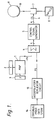
- the apparatus shown in Figure 1 comprises a half-tone dot generator including a store 1 defining half-tone dot information.
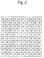
- a simple example of the half-tone dot information where the dot lattice axes are aligned with the scan direction is shown in Figure 2.
- This map shows the 10 x 10 textel dot unit cell value ranging from 0 to 99 dot %. In a real device the unit cell is approximately 12 units square skewed at some angle to the scan direction, with values ranged to be in the same units as the source data.
- the map is addressed by X and Y address generators 2, 3 which track the position of the exposing laser beams, to be described below, on a record medium.
- the store 1 is connected to an adder circuit 4 such that the inverse of the addressed value from the store 1 (-PV) is applied to the adder 4.
- a picture signal PS
- the generation of this picture signal PS will be explained in more detail below.
- the picture signal defines colour density values for each pixel of a colour component corresponding to the separation being generated.
- the output signal from the adder circuit 4 is fed to a control signal generator 5 which generates a control signal which is fed to a laser beam modulator 7 which controls the intensity of a laser beam from a laser 8, while the beam impinges on a record medium 10 mounted on a rotatable cylinder 11. Relative movement is caused, in a conventional manner, between the beam and the cylinder 11 such that the radiation beam scans along a series of abutting scan lines across the record medium 10.
- Each control signal usually constitutes a binary value of one or zero such that if the control signal (CS) is binary zero then modulator 7 reduces the intensity of the outgoing laser beam whereas if the control signal CS has a value one then the full intensity beam will pass to the record medium 10.
- the laser beam may have an intermediate value, particularly at the edge of a half-tone dot.
- the laser beam may be split up into many beams e.g. six, each of which is modulated in the same manner as a single beam.
- each beam on the record medium 10 is continuously monitored in a conventional manner and the location of impingement of each beam is represented by respective X and Y values which are used to address the map 1.
- the apparatus is used to generate a half-tone reproduction of an original image which will have been generated in a conventional manner so as to be represented by a series of digital data values corresponding to pixels of that original image at a first resolution.
- Figure 3 illustrates a small portion of the original image in terms of pixel positions, the original pixels being labelled "X". These pixel values may be fed directly to an interpolator/replicator circuit 13 or may be stored in a data store 14 (as shown in Figure 1).
- the interpolator/replicator circuit 13 is omitted and the store 14 is addressed directly so as to pass each pixel value in turn to the adder circuit 4.
- the pixel values will represent colour density percentages for the colour component concerned although other representations of colour density could also be used.
- the same representation should be used to represent the original pixels and the data values in this store 1.
- each pixel may be represented by a value ranging between zero and one hundred. In other words a percentage value.
- the store 1 need only contain the 100 values of a 10 x 10 unit cell. More commonly the screen is at some angle to the scan direction so as to give a repeat in the scan direction after passing through several unit cells. Store 1 would then contain the new giant unit cell containing many dot unit cells. In some cases it is possible to reduce the amount of data in store where the data in one row or column is repeated in another.
- store 1 For each element, store 1 is accessed to provide a digital value which is compared with the picture signal PS to determine whether the laser beam concerned should expose or not expose the corresponding part of the record medium depending on whether or not PS is greater than the digital value.
- the third resolution is three times the first resolution in each direction, other multiples are possible up to the finest, second resolution.
- the same algorithm is then used in the other dimension to generate sub-pixel 29. This type of interpolation can inherently cause an unsharp mask to be applied. Following this, the sub-pixels are replicated up to the second resolution.
- the invention is primarily for use in generating a number of colour separations corresponding to a coloured image, it is also suitable for generating reproductions of monochrome images.
Landscapes
- Engineering & Computer Science (AREA)
- Multimedia (AREA)
- Signal Processing (AREA)
- Physics & Mathematics (AREA)
- General Physics & Mathematics (AREA)
- Theoretical Computer Science (AREA)
- Facsimile Image Signal Circuits (AREA)
- Editing Of Facsimile Originals (AREA)
- Image Processing (AREA)
- Facsimile Scanning Arrangements (AREA)
Description
- The invention relates to methods and apparatus for generating a half-tone version of an image.
- To an approximation most halftone output scanners may be considered to be producing a bilevel image: that is one that is either black or white with no intermediate shades of grey. The exposure is often done by exposing the film in elemental areas or textels. Consider the hard dot output case where the exposure can have only two binary states - 0 (light) or 1 (dark). The image to be outputted is digitised in elemental areas or pixels. It is usual practice for the textel size to be considerably smaller than the pixel size or the repeat in the dot pattern. For example images digitised at a resolution of 12 pixels/mm are commonly output with a halftone screen pitch of 6 dots/mm and a resolution of 72 textels/mm. In this example the textel frequency is six times the pixel frequency.
- In a conventional hard dot output scanner the halftones may be generated as follows. The pixel data is replicated to achieve the textel resolution. The replicated pixel data is then added to a regular screen function - if the sum is greater than a threshold then the corresponding textel value is set to 1 (dark), otherwise it is set to 0 (light). The textel data is then used to expose the film.
- Examples of such conventional techniques are described in the document "A survey of Techniques for the Display of Continuous Tone Pictures on Bilevel Displays" by Jarvis et al. published in the Journal of Computer Graphics and Image Processing 5, 13-40 , Academic Press 1976
Replicating the pixel data to get to textel resolution has some disadvantages. Where the pixel values are varying considerably from one to the next then the resulting dot shapes may have sharp corners and edges. These are often hard to print and can lead to differences between the proofing process performance and the printing process it is supposed to simulate. This can also give aliasing problems when the original data has had its sharpness digitally enhanced too much. - A possible solution described in our co-pending European patent application EP-A-0247830 involves scanning the original image in a series of overlapped scan lines. In this way, the number of input pixels is increased, typically doubled which will automatically lead to an increase in spatial resolution. However, one problem with this process is that there is a significant increase in scanning time required.
- US-A-4258393 describes a picture element processing method in which a picture element is divided into four smaller picture elements whose densities are determined from the algebraic mean value of the densities of the picture element and surrounding picture elements. This approach leads to a general smoothing of the picture element values but is restricted in its use of an algebraic sum to obtain the values and the requirement that each value should be obtained in this manner. Where high resolution output is required, the process would be unduly slow.
- In accordance with one aspect of the present invention, a method of generating a half-tone version of an image, represented by a first set of digital data defining the colour content of abutting pixels of the image at a first resolution, in which a record medium is selectively exposed to an exposing beam which is scanned across the record medium and whose intensity is controlled by a control signal representing image pixels at a second, finer resolution, the control signal being generated by comparing a second set of digital data, derived from the first set of digital data and representing the colour content of the image at the second resolution, with half-tone information defining an array of half-tone dot elements at the second resolution, each element being associated with a respective threshold value, whereby each data value of the second set of data is compared with a respective threshold value chosen in accordance with the position of the exposing beam within the half-tone dot currently being exposed and the control signal (CS) value varying in accordance with whether or not the data value exceeds the threshold is characterised in that the second set of digital data is obtained from the first set by interpolating a third set of digital data defining image pixels at a third resolution finer than the first resolution but coarser than the second resolution, and thereafter replicating the third set of image data to obtain the second set.
Preferably, the control signal generator obtains the second set of digital data from the first set of digital data by interpolating a third set of digital data defining image pixels at a third resolution finer than the first resolution but no finer than the second resolution, and thereafter replicating the third set of image data to obtain the second set. - In accordance with a second aspect of the invention, we provide a method of generating a half-tone version of an image, represented by a first set of digital data defining the colour content of abutting pixels of the image at a first resolution, in which a record medium is selectively exposed to an exposing beam which is scanned across the record medium and whose intensity is controlled by a control signal representing image pixels at a second, finer resolution, the control signal being generated by comparing a second set of digital data, derived from the first set of digital data and representing the colour content of the image at the second resolution, with half-tone information defining an array of half-tone dot elements at the second resolution, each element being associated with a respective threshold value, whereby each data value of the second set of data is compared with a respective threshold value chosen in accordance with the position of the exposing beam within the half-tone dot currently being exposed and the control signal (CS) value varying in accordance with whether or not the data value exceeds the threshold is characterised in that the control signal generator obtains the second set of digital data from the first set of digital data by interpolating a third set of digital data defining image pixels at a third resolution finer than the first resolution but coarser than the second resolution, and thereafter replicating the third set of image data to obtain the second set.
Preferably, the control signal generator at least interpolates the third set of data from the first set of data by a method in which an interpolated value (PV) is interpolated from values selected from the first set of digital data P₁-P₄ corresponding to the four neighbouring pixels in accordance with the formula:

where A-D are weighting coefficients and
- We have devised a new process and apparatus in which processes such as feature enhancement or tone smoothing can be performed within the half-tone dot generator rather than upstream of the dot generator as has previously been the case. This allows the apparent sharpness of the half-tone output to be matched to the continuous tone original image.
- It will be appreciated, that this invention makes use of the fact that in conventional half-tone reproduction processes, each half-tone dot is defined at a second, textel resolution much higher than the original first, pixel resolution.
- The method and apparatus can be used to apply a variety of functions, for example an unsharp masking algorithm, or a function to improve the reproduction accuracy of an output scanner.
- The exposing beam may have any conventional form for example an ink jet or radiation beam.
- The invention is applicable to the modulation of a single radiation beam but may also be used where the radiation beam comprises a plurality of subsidiary beams each of which is modulated by the same control signal in a single pass across the record medium. In addition to this, however, each subsidiary radiation beam may be individually further modulated, if desired, to achieve additional accuracy as described, for example, in EP-A-0151353.
- An example of a method and apparatus in accordance with the present invention will now be described with reference to the accompanying drawings, in which:-
- Figure 1 is a block diagram of the apparatus;
- Figure 2 illustrates the half-tone dot information corresponding to a single dot cell; and,
- Figure 3 illustrates schematically the arrangement of original image pixels at a first resolution and subsequently generated third resolution pixels.
- The apparatus shown in Figure 1 comprises a half-tone dot generator including a store 1 defining half-tone dot information. A simple example of the half-tone dot information where the dot lattice axes are aligned with the scan direction is shown in Figure 2. This map shows the 10 x 10 textel dot unit cell value ranging from 0 to 99 dot %. In a real device the unit cell is approximately 12 units square skewed at some angle to the scan direction, with values ranged to be in the same units as the source data. The map is addressed by X and
Y address generators adder circuit 4 such that the inverse of the addressed value from the store 1 (-PV) is applied to theadder 4. In addition, a picture signal (PS) is applied to the other input of theadder 4. The generation of this picture signal PS will be explained in more detail below. However, the picture signal defines colour density values for each pixel of a colour component corresponding to the separation being generated. - The output signal from the
adder circuit 4 is fed to acontrol signal generator 5 which generates a control signal which is fed to a laser beam modulator 7 which controls the intensity of a laser beam from alaser 8, while the beam impinges on arecord medium 10 mounted on arotatable cylinder 11. Relative movement is caused, in a conventional manner, between the beam and thecylinder 11 such that the radiation beam scans along a series of abutting scan lines across therecord medium 10. - Each control signal usually constitutes a binary value of one or zero such that if the control signal (CS) is binary zero then modulator 7 reduces the intensity of the outgoing laser beam whereas if the control signal CS has a value one then the full intensity beam will pass to the
record medium 10. In a modification, the laser beam may have an intermediate value, particularly at the edge of a half-tone dot. - In a further modification, the laser beam may be split up into many beams e.g. six, each of which is modulated in the same manner as a single beam.
- The position of each beam on the
record medium 10 is continuously monitored in a conventional manner and the location of impingement of each beam is represented by respective X and Y values which are used to address the map 1. - The apparatus is used to generate a half-tone reproduction of an original image which will have been generated in a conventional manner so as to be represented by a series of digital data values corresponding to pixels of that original image at a first resolution. Figure 3 illustrates a small portion of the original image in terms of pixel positions, the original pixels being labelled "X". These pixel values may be fed directly to an interpolator/
replicator circuit 13 or may be stored in a data store 14 (as shown in Figure 1). - Conventionally, the interpolator/
replicator circuit 13 is omitted and thestore 14 is addressed directly so as to pass each pixel value in turn to theadder circuit 4. Typically, the pixel values will represent colour density percentages for the colour component concerned although other representations of colour density could also be used. In any event, the same representation should be used to represent the original pixels and the data values in this store 1. In the present case, it will be assumed that each pixel may be represented by a value ranging between zero and one hundred. In other words a percentage value. - In a simple example the store 1 need only contain the 100 values of a 10 x 10 unit cell. More commonly the screen is at some angle to the scan direction so as to give a repeat in the scan direction after passing through several unit cells. Store 1 would then contain the new giant unit cell containing many dot unit cells. In some cases it is possible to reduce the amount of data in store where the data in one row or column is repeated in another.
- For each element, store 1 is accessed to provide a digital value which is compared with the picture signal PS to determine whether the laser beam concerned should expose or not expose the corresponding part of the record medium depending on whether or not PS is greater than the digital value.
- For example consider a region of flat tint of 25 dot % and store 1 contains the simple unit cell data of Fig. 2. In this case PS = 25 throughout, so the film would be exposed for the diamond shaped region of Fig. 2 with values 0 - 24, and unexposed otherwise. This is achieved simply in the
adder 4 by comparing the picture signal with each elemental value and causing the beam to be exposed if the picture signal is greater than the elemental value. Conventionally the second (textel) resolution signal PS is taken to be equal to the nearest first resolution pixel value. In Fig. 3 where the original pixel values are represented with an "x", the signal PS would be equal to thepixel value 20 within the square 21 but discontinuous at the boundary. This discontinuity can lead to the anomalous high frequency effects previously described. - With an intermediate resolution interpolation, represented by "." in Fig. 3, the
value 22 is only held to be constant over thesmaller square 23, the effects of the discontinuity are reduced, and the half-tone image is improved. - It will be noted that the number of scanned pixel values remains the same and that there is no increase in the scanning time required over the conventional process.
- Although the example has been described in which the third resolution is three times the first resolution in each direction, other multiples are possible up to the finest, second resolution.
- Various methods may be used to generate the sub-pixel values within the interpolator/
replicator circuit 13. In one method, a new sub-pixel, for example the sub-pixel 28 in Figure 3 is generated from the 4 adjacent original pixel values P₁₋P₄ using the one dimensional formula:

where A - D are weighting coefficients chosen so as to define a cubic interpolation algorithm and where
sub-pixel 29. This type of interpolation can inherently cause an unsharp mask to be applied. Following this, the sub-pixels are replicated up to the second resolution. - If it is desired to smooth the image then a cubic spline interpolation could be used.
- Although the invention is primarily for use in generating a number of colour separations corresponding to a coloured image, it is also suitable for generating reproductions of monochrome images.
Claims (6)
- A method of generating a half-tone version of an image, represented by a first set of digital data defining the colour content of abutting pixels of the image at a first resolution, in which a record medium is selectively exposed to an exposing beam which is scanned across the record medium and whose intensity is controlled by a control signal representing image pixels at a second, finer resolution, the control signal being generated by comparing a second set of digital data, derived from the first set of digital data and representing the colour content of the image at the second resolution, with half-tone information defining an array of half-tone dot elements at the second resolution, each element being associated with a respective threshold value, whereby each data value of the second set of data is compared with a respective threshold value chosen in accordance with the position of the exposing beam within the half-tone dot currently being exposed and the control signal (CS) value varying in accordance with whether or not the data value exceeds the threshold characterised in that the second set of digital data is obtained from the first set by interpolating a third set of digital data defining image pixels at a third resolution finer than the first resolution but coarser than the second resolution, and thereafter replicating the third set of image data to obtain the second set.
- A method according to claim 1 wherein the third set of data is at least partly interpolated from the first set of data by a method in which an interpolated value (PV) is interpolated from values selected from the first set of digital data P₁-P₄ corresponding to the four neighbouring pixels in accordance with the formula:

where A-D are weighting coefficients and
- A method according to claim 1 or claim 2, wherein each half-tone dot section comprises a square array of dot elements at the second resolution.
- A method according to any of the preceding claims, wherein the interpolation is such as to enhance features in the reproduced image by applying an unsharp masking algorithm.
- Apparatus for generating a half-tone version of an image, represented by a first set of digital data defining the colour content of abutting pixels of the image at a first resolution, the apparatus comprising recording means (8) for generating an exposing beam; a record medium support (11), wherein the recording means and the support are relatively moveable such that an image can be recorded on a record medium (10) mounted on the support by scanning the exposing beam across the recording medium in a series of abutting scan lines; and a control signal generator (5) for generating a control signal (CS) representing image pixels at a second, finer resolution by controlling the intensity of the exposing beam, which is fed to the recording means (8) such that a record medium on the support (11) is selectively exposed at the second, finer resolution, the control signal generator (5) being adapted to generate the control signal by comparing a second set of digital data derived from the first set of digital data and representing the colour content of the image at the second resolution, with half-tone information defining an array of half-tone dot elements at the second resolution, each element being associated with a respective threshold value, whereby each data value of the second set of data is compared with a respective threshold value chosen in accordance with the position of the exposing beam within the half-tone dot currently being exposed and the control signal (CS) value varying in accordance with whether or not the data value exceeds the threshold characterised in that the control signal generator obtains the second set of digital data from the first set of digital data by interpolating a third set of digital data defining image pixels at a third resolution finer than the first resolution but coarser than the second resolution, and thereafter replicating the third set of image data to obtain the second set.
- Apparatus according to claim 5, wherein the control signal generator at least interpolates the third set of data from the first set of data by a method in which an interpolated value (PV) is interpolated from values selected from the first set of digital data P₁-P₄ corresponding to the four neighbouring pixels in accordance with the formula:

where A-D are weighting coefficients and
Applications Claiming Priority (2)
| Application Number | Priority Date | Filing Date | Title |
|---|---|---|---|
| GB8811568 | 1988-05-16 | ||
| GB888811568A GB8811568D0 (en) | 1988-05-16 | 1988-05-16 | Producing half-tone images |
Publications (2)
| Publication Number | Publication Date |
|---|---|
| EP0342845A1 EP0342845A1 (en) | 1989-11-23 |
| EP0342845B1 true EP0342845B1 (en) | 1993-12-22 |
Family
ID=10636978
Family Applications (1)
| Application Number | Title | Priority Date | Filing Date |
|---|---|---|---|
| EP89304680A Expired - Lifetime EP0342845B1 (en) | 1988-05-16 | 1989-05-09 | Producing half-tone images |
Country Status (5)
| Country | Link |
|---|---|
| US (1) | US4989096A (en) |
| EP (1) | EP0342845B1 (en) |
| JP (1) | JPH0271669A (en) |
| DE (1) | DE68911588T2 (en) |
| GB (1) | GB8811568D0 (en) |
Families Citing this family (13)
| Publication number | Priority date | Publication date | Assignee | Title |
|---|---|---|---|---|
| US5229868A (en) * | 1989-08-25 | 1993-07-20 | Matsushita Electric Industrial Co., Ltd. | Method and apparatus for converting a line density of a bi-level image signal |
| DE69027723T2 (en) * | 1989-09-07 | 1997-01-09 | Canon Kk | Image display device |
| JP3096910B2 (en) * | 1989-12-19 | 2000-10-10 | 株式会社リコー | Image recording device |
| US5204760A (en) * | 1990-08-27 | 1993-04-20 | Kabushiki Kaisha Toshiba | System and method for converting continuous half tone image into pseudo half tone image |
| ES2103829T3 (en) * | 1990-11-21 | 1997-10-01 | Polaroid Corp | A PRINTING PROCEDURE. |
| US5341228A (en) * | 1990-12-04 | 1994-08-23 | Research Corporation Technologies | Method and apparatus for halftone rendering of a gray scale image using a blue noise mask |
| WO1992012495A1 (en) * | 1990-12-31 | 1992-07-23 | E.I. Du Pont De Nemours And Company | Method of resizing an image, designing a filter therefor, and mapping the output image to the input image |
| US5239625A (en) * | 1991-03-05 | 1993-08-24 | Rampage Systems, Inc. | Apparatus and method to merge images rasterized at different resolutions |
| US5515182A (en) * | 1992-08-31 | 1996-05-07 | Howtek, Inc. | Rotary scanner |
| IL105343A (en) * | 1993-04-08 | 1997-02-18 | Scitex Corp Ltd | Apparatus and technique for generating a screen reproduction of an image |
| FR2743241B1 (en) * | 1995-12-28 | 1998-02-13 | Sagem | METHOD FOR MODIFYING THE RESOLUTION OF A DIGITAL IMAGE |
| US5914725A (en) * | 1996-03-07 | 1999-06-22 | Powertv, Inc. | Interpolation of pixel values and alpha values in a computer graphics display device |
| CN113689334B (en) * | 2021-08-24 | 2024-12-03 | 深圳市先地图像科技有限公司 | Laser imaging device and laser imaging control method |
Family Cites Families (11)
| Publication number | Priority date | Publication date | Assignee | Title |
|---|---|---|---|---|
| US4068266A (en) * | 1976-06-03 | 1978-01-10 | Xerox Corporation | Statistical resolution conversion technique |
| JPS54126415A (en) * | 1978-03-24 | 1979-10-01 | Ricoh Co Ltd | High-density picture element forecasting-restoring method |
| JPS5563173A (en) * | 1978-11-06 | 1980-05-13 | Ricoh Co Ltd | Picture signal processing system |
| US4280144A (en) * | 1979-12-03 | 1981-07-21 | International Business Machines Corporation | Coarse scan/fine print algorithm |
| US4419690A (en) * | 1980-09-01 | 1983-12-06 | Crosfield Electronics Limited | Method and apparatus for producing a half-tone reproduction |
| EP0070677B1 (en) * | 1981-07-14 | 1991-01-09 | Dai Nippon Printing Co., Ltd. | Video printing apparatus |
| JPS6191772A (en) * | 1984-10-11 | 1986-05-09 | Canon Inc | Image processing device |
| US4736254A (en) * | 1984-11-22 | 1988-04-05 | Matsushita Electric Industrial Co., Ltd. | Method and apparatus for generating pseudo-halftone dots by comparing gray scale values of an original with dither threshold values stored in cells of a matrix array divided into imaginary matrices of elemental areas each containing one cell |
| US4644409A (en) * | 1985-02-26 | 1987-02-17 | Advanced Micro Devices, Inc. | Document resolution-adaption method and apparatus |
| US4841375A (en) * | 1986-05-29 | 1989-06-20 | Kabushiki Kaisha Toshiba | Image-resolution conversion apparatus for converting a pixel-density of image data |
| GB8628238D0 (en) * | 1986-11-26 | 1986-12-31 | Crosfield Electronics Ltd | Generating half-tone representations |
-
1988
- 1988-05-16 GB GB888811568A patent/GB8811568D0/en active Pending
-
1989
- 1989-05-09 DE DE89304680T patent/DE68911588T2/en not_active Expired - Fee Related
- 1989-05-09 EP EP89304680A patent/EP0342845B1/en not_active Expired - Lifetime
- 1989-05-15 JP JP1118826A patent/JPH0271669A/en active Pending
- 1989-05-16 US US07/352,521 patent/US4989096A/en not_active Expired - Fee Related
Non-Patent Citations (1)
| Title |
|---|
| "A survey of Techniques for the Display of Continuous Tone Pictures on Bilevel Displays". Computer Graphics and Image Processing 5, 13-40 (1976) by JARVIS, JUDICE AND NINKE. Academic Press 1976 * |
Also Published As
| Publication number | Publication date |
|---|---|
| US4989096A (en) | 1991-01-29 |
| GB8811568D0 (en) | 1988-06-22 |
| DE68911588T2 (en) | 1994-04-14 |
| DE68911588D1 (en) | 1994-02-03 |
| EP0342845A1 (en) | 1989-11-23 |
| JPH0271669A (en) | 1990-03-12 |
Similar Documents
| Publication | Publication Date | Title |
|---|---|---|
| US4339774A (en) | Apparatus and method for generating a dispersed dot half tone picture from a continuous tone picture | |
| US5583660A (en) | Non-perpendicular, equal frequency non-conventional screen patterns for electronic halftone generation | |
| US5323245A (en) | Perpendicular, unequal frequency non-conventional screen patterns for electronic halftone generation | |
| EP0814431B1 (en) | Subpixel character positioning with antialiasing with grey masking techniques | |
| CA1114747A (en) | Electronic halftone screening with halftone cells approximating a parallelogram | |
| EP0201674B1 (en) | A method for reproducing multi-level digital images on a bi-level printer of fixed dot size | |
| EP0749232A1 (en) | Method and apparatus for halftone rendering of a gray scale image using a blue noise mask | |
| EP0481602B1 (en) | A general kernel function for electronic halftone generation | |
| US4413286A (en) | Method and apparatus involving digital screen generation | |
| EP0342845B1 (en) | Producing half-tone images | |
| US5515456A (en) | Process for providing digital halftone image with random error diffusion, color correction and enlargement | |
| JPH04213964A (en) | Photographic picture playback apparatus giving digital half-tone to screen picture facilitating adjustable roughness | |
| US5140431A (en) | Digital electronic system for halftone printing | |
| US5805724A (en) | Method and system for hybrid error diffusion processing of image information using dynamic screens based on brightness/darkness settings | |
| EP0642258B1 (en) | Method for generating a frequency modulated halftone image | |
| EP0235631B1 (en) | Method of forming halftone screen | |
| JPH06105129A (en) | Apparatus and method for electronic hi-fi screenless conversion using separable filter | |
| US5264926A (en) | Perpendicular, equal frequency non-conventional screen patterns for electronic halftone generation | |
| US6344870B1 (en) | Methods of providing lower resolution format data into higher resolution format | |
| US6097502A (en) | Multilevel screening for color laser printer | |
| US5258832A (en) | Non-perpendicular, unequal frequency non-conventional screen patterns for electronic halftone generation | |
| US6411745B1 (en) | Method and apparatus to reduce cross-interference in reproduction of scanned halftone images | |
| EP0696131B1 (en) | A method and system for processing image information using screening and error diffusion | |
| EP0361538A1 (en) | Method and system for edge enhancement in reproducing multi-level digital images on a bi-level printer of fixed dot size | |
| EP0451995B1 (en) | Methods and apparatus for half-tone imaging |
Legal Events
| Date | Code | Title | Description |
|---|---|---|---|
| PUAI | Public reference made under article 153(3) epc to a published international application that has entered the european phase |
Free format text: ORIGINAL CODE: 0009012 |
|
| AK | Designated contracting states |
Kind code of ref document: A1 Designated state(s): DE GB |
|
| 17P | Request for examination filed |
Effective date: 19900315 |
|
| RAP1 | Party data changed (applicant data changed or rights of an application transferred) |
Owner name: CROSFIELD ELECTRONICS LIMITED |
|
| 17Q | First examination report despatched |
Effective date: 19920319 |
|
| RAP1 | Party data changed (applicant data changed or rights of an application transferred) |
Owner name: CROSFIELD ELECTRONICS LIMITED |
|
| GRAA | (expected) grant |
Free format text: ORIGINAL CODE: 0009210 |
|
| AK | Designated contracting states |
Kind code of ref document: B1 Designated state(s): DE GB |
|
| REF | Corresponds to: |
Ref document number: 68911588 Country of ref document: DE Date of ref document: 19940203 |
|
| PLBE | No opposition filed within time limit |
Free format text: ORIGINAL CODE: 0009261 |
|
| STAA | Information on the status of an ep patent application or granted ep patent |
Free format text: STATUS: NO OPPOSITION FILED WITHIN TIME LIMIT |
|
| 26N | No opposition filed | ||
| PGFP | Annual fee paid to national office [announced via postgrant information from national office to epo] |
Ref country code: GB Payment date: 19980430 Year of fee payment: 10 |
|
| PGFP | Annual fee paid to national office [announced via postgrant information from national office to epo] |
Ref country code: DE Payment date: 19980515 Year of fee payment: 10 |
|
| REG | Reference to a national code |
Ref country code: GB Ref legal event code: 732E |
|
| PG25 | Lapsed in a contracting state [announced via postgrant information from national office to epo] |
Ref country code: GB Free format text: LAPSE BECAUSE OF NON-PAYMENT OF DUE FEES Effective date: 19990509 |
|
| GBPC | Gb: european patent ceased through non-payment of renewal fee |
Effective date: 19990509 |
|
| PG25 | Lapsed in a contracting state [announced via postgrant information from national office to epo] |
Ref country code: DE Free format text: LAPSE BECAUSE OF NON-PAYMENT OF DUE FEES Effective date: 20000301 |