EP0235478A2 - Prüfvorrichtung für Bohrlochverrohrungen - Google Patents
Prüfvorrichtung für Bohrlochverrohrungen Download PDFInfo
- Publication number
- EP0235478A2 EP0235478A2 EP86402878A EP86402878A EP0235478A2 EP 0235478 A2 EP0235478 A2 EP 0235478A2 EP 86402878 A EP86402878 A EP 86402878A EP 86402878 A EP86402878 A EP 86402878A EP 0235478 A2 EP0235478 A2 EP 0235478A2
- Authority
- EP
- European Patent Office
- Prior art keywords
- electrodes
- casing
- housing
- amplifier
- cable
- Prior art date
- Legal status (The legal status is an assumption and is not a legal conclusion. Google has not performed a legal analysis and makes no representation as to the accuracy of the status listed.)
- Granted
Links
Images




Classifications
-
- E—FIXED CONSTRUCTIONS
- E21—EARTH OR ROCK DRILLING; MINING
- E21B—EARTH OR ROCK DRILLING; OBTAINING OIL, GAS, WATER, SOLUBLE OR MELTABLE MATERIALS OR A SLURRY OF MINERALS FROM WELLS
- E21B47/00—Survey of boreholes or wells
- E21B47/09—Locating or determining the position of objects in boreholes or wells, e.g. the position of an extending arm; Identifying the free or blocked portions of pipes
-
- E—FIXED CONSTRUCTIONS
- E21—EARTH OR ROCK DRILLING; MINING
- E21B—EARTH OR ROCK DRILLING; OBTAINING OIL, GAS, WATER, SOLUBLE OR MELTABLE MATERIALS OR A SLURRY OF MINERALS FROM WELLS
- E21B17/00—Drilling rods or pipes; Flexible drill strings; Kellies; Drill collars; Sucker rods; Cables; Casings; Tubings
- E21B17/10—Wear protectors; Centralising devices, e.g. stabilisers
- E21B17/1014—Flexible or expansible centering means, e.g. with pistons pressing against the wall of the well
- E21B17/1021—Flexible or expansible centering means, e.g. with pistons pressing against the wall of the well with articulated arms or arcuate springs
-
- G—PHYSICS
- G01—MEASURING; TESTING
- G01N—INVESTIGATING OR ANALYSING MATERIALS BY DETERMINING THEIR CHEMICAL OR PHYSICAL PROPERTIES
- G01N17/00—Investigating resistance of materials to the weather, to corrosion, or to light
- G01N17/02—Electrochemical measuring systems for weathering, corrosion or corrosion-protection measurement
Definitions
- the present invention generally relates to an apparatus for diagnosing the condition of an elongated casing, and, in particular, to a diagnostic apparatus for diagnosing and examining the electrical condition of an elongated casing, such as a metal pipe. More specifically, the present invention relates to a borehole casing diagnostic apparatus which may be fitted into a long borehole casing fitted into a borehole extending in the earth so as to evaluate cathodic protection and to give a corrosion rate measurement of the casing.
- cathodic protection is often used.
- Cathodic protection is well known in the art, and this is the technique to protect a metal from electrochemical corrosion by making the cathode of an electrochemical cell. Cathodic protection has been and is being used for metal casings fitted into boreholes extending in the earth.
- the casing potential profile along the longitudinal direction of the casing is measured.
- a downhole apparatus provided with a plurality of electrodes is fitted into the casing as suspended by a long cable, which is connected to a measurement unit located at the ground surface, and measurements are taken by the measurement unit at the ground surface by traversing the downhole apparatus along the casing.
- the proposed technique allows to significantly improve the quality of data collected, but it still necessitates to carry out measurement through the long cable since the measurement unit is located at the ground surface. As long as measurements are to be carried out at the ground surface, measurement times will be long due to the need to average or integrate data because of crosstalk and noise problems which occur with remote measurements through the long cable.
- the downhole apparatus in order to carry out potential difference measurements along the longitudinal axis of a casing, the downhole apparatus is typically provided with a plurality of electrodes arranged along the longitudinal axis of the downhole apparatus as spaced apart from each other. Accordingly, it is typically assumed that there is no appreciable potential difference or current in the circumferential direction or it is simply neglected. It is true that U.S.P. 3,207,981 issued to Marsh et al. on September 21, 1965 discloses a downhole apparatus including a plurality of electrodes which are disposed circumferentially. However, this patent only teaches to dispose the plurality of electrodes at the same and single circumference, it neglects the potential difference or current components in the longitudinal direction.
- this patent is concerned with pipe thickness and identifying regions of metal loss, and it only measures potential differences when currents are injected from other electrodes to give a circumferential resistance measurement or comparison of two resistance measurements. It does not measure potential difference as a property in its own right, or for the purposes of measuring natural or externally impressed current.
- Another object of the present invention is to provide an improved casing diagnostic apparatus which may be fitted into a casing, such as a borehole casing, and which includes a measurement unit as disposed therein thereby allowing to carry out downhole measurements locally and directly.
- a further object of the present invention is to provide an improved casing diagnostic apparatus capable of carrying out measurements of predetermined electrical property of the casing, in which the apparatus is fitted, not only in the longitudinal direction of the casing but also in the circumferential direction thereof.
- a still further object of the present invention is to provide an improved casing diagnostic downhole apparatus capable of determining the local corrosion rate at high accuracy as well as at high speed.
- a still further object of the present invention is to provide an improved casing diagnostic downhole apparatus capable of carrying out measurements as submerged in well liquids which are relatively high in electrical conductivity, such as brine.
- a casing diagnostic downhole apparatus generally in the shape of a torpedo, which may be fitted into a long casing and which directly measures a predetermined local electrical property of the casing, such as an electrical impedance, potential difference or casing resistance between two points on the casing.
- the casing diagnostic downhole apparatus includes a measurement unit as incorporated therein, which typically includes an amplifier circuit and an analog-to-digital converter.
- the downhole apparatus also includes a plurality of electrodes which are mounted on a housing so as to be movable with respect thereto between a retracted position where the electrodes are received in a predefined space in the housing and an advanced position where the electrodes are forced into contact with the casing.
- the measurement unit inside of the downhole apparatus is connected to the electrodes by means of switches to take measurements of at least one predetermined electrical property between any two selected electrodes in contact with the casing, and, after converting the measured values into digital data, the measurement unit transmits the digital data to a surface processing system including a computer through a cable.
- data transmission between the downhole apparatus and the surface processing unit may be carried out digitally, and noise immunity is enhanced significantly.
- crosstalk is no longer a problem in the present invention, measurements can be taken in parallel in the case when two or more pairs of electrodes are provided.
- individual measurements can be taken in shorter time with less averaging or integration steps. This is particularly true for the casing resistance measurement step where crosstalk problems are severe.
- the amplifier circuit of the measurement unit provided in the downhole apparatus has a two-stage structure, each stage including a reset stabilized operational amplifier which includes a main d.c. amplifier and a negative feedback loop for cancelling large amplifier offset voltages of the main d.c. amplifier automatically.
- the feedback loop includes sampling means for sampling an offset voltage of the main d.c. amplifier and holding means for temporarily holding the offset voltage thus sampled, which is then supplied as an input to the main d.c. amplifier for subtraction.
- the holding means includes a capacitor connected between the feedback loop and a reference potential, normally ground, and the sampling means includes a switch and an a.c. offset amplifier connected in series in the feedback loop between the output of the main d.c.
- the a.c. offset amplifier includes two capacitors connected in series with a d.c. amplifier.
- the measurement unit also includes at least one current source for supplying a predetermined current between selected electrodes thereby allowing contact resistance between the electrodes and the casing to be measured.
- the information of contact resistance may be advantageously used as quality control for data taken.
- a casing diagnostic downhole apparatus which includes a plurality of arm assemblies which are provided in the housing as spaced apart from each other in the longitudinal direction of the downhole apparatus.
- Each of the arm assemblies includes a plurality of arms which are pivotal radially and each of which carries an electrode thereon.
- the plurality of electrodes are thus arranged at different axial levels and different circumferential positions in one axial level.
- Such an axially and circumferentially arranged multi-electrode system allows data of high reliability and high accuracy to be recorded.
- the electrodes of the present invention are also arranged at different axial multi-spacings. Having various axial spacings affords different resolutions. For example, if currents in the casing are large, small spacing measurements will give high resultion. If currents in the casing are low, a large spacing measurement will give acceptable accuracy when the signal level for the short spacing is too low.
- the electrodes arranged at different locations axially as well as circumferentially the potential difference between any two points on the casing and the current flowing in any direction in the casing can be measured, if a sufficient number of electrodes are provided.
- two or more data can be taken at the same time with the multi-electrode arrangement.
- parallel measurements taken for two or more pairs of electrodes with the same axial spacing can be used as quality control.
- difference between different axial measurements with the same spacing at the same axial position but different circumferential position can be used as an indicator of localised corrosion.
- Another advantage of multi-electrode measurements is the increased probability of recording valid data if contact conditions of the electrodes are poor.
- the probability of recording a valid measurement is P4 if the probability of a single electrode making good contact is P.
- the probability of one of the three measurements being valid is (1-(1-P)3)2(1-(1-P2)3).
- the probability of the single measurement being valid would be even higher, i.e., (1-(1-P)3)4.
- a casing diagnostic downhole apparatus including a plurality of electrodes each of which is enclosed in an electrically insulating material excepting a predetermined section which comes into contact with the casing when the electrodes are moved to its advanced position.
- an enclosed structure allows to use the present apparatus when it is submerged in any kind of fluid, electrically conductive or non-conductive.
- the casing is often filled with a relatively electrically conductive fluid, such as brine.
- the electrically insulating material may be provided in the form of a coating or molding on each of the electrodes. Alternatively or additionally, the insulating material may be formed in the form of a separate packer having a slit, which covers the corresponding electrode.
- each electrode is preferably construced as a single piece element. This single piece feature provides an advantage of creating no contact potential within the electrode. It is also preferable to make each electrode from a single metal because this also eliminates the possibility of setting up galvanic cells within the electrode should any conductive fluid come into contact with the electrode. In addition, it is also preferable that each electrode is comprised of a material which is similar or identical to that of the casing to which the electrode is brough into contact to prevent formation of a galvanic cell between the casing and the electrode if any conductive fluid contacts the electrode.
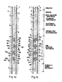
- Fig. 1a is a schematic illustration showing a casing diagnostic downhole apparatus 1 constructed in accordance with one embodiment of the present invention when applied to diagnosis of borehole casing wherein the arm assemblies 12 of the downhole apparatus 1 are set in the retracted position;
- Fig. 1b is a schematic illustration showing the downhole apparatus 1 with the arm assemblies 12 in the advanced position so as to keep the electrodes A through D in contact with the casing 3;
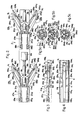
- Fig. 2 is a schematic illustration, on an enlarged scale and generally taken along the line V-V indicated in Fig. 5a, showing the detailed structure of the arm actuator section 10 of the downhole apparatus 1 with the arm assemblies in the advanced position;
- Fig. 1a is a schematic illustration showing a casing diagnostic downhole apparatus 1 constructed in accordance with one embodiment of the present invention when applied to diagnosis of borehole casing wherein the arm assemblies 12 of the downhole apparatus 1 are set in the retracted position
- Fig. 1b is a schematic illustration showing the downhole apparatus 1 with the arm assemblies 12 in the advanced position
- FIG. 3 is a schematic illustration showing part of the arm actuator section 10 of the downhole apparatus 1 with the arm assembly 12 in the retracted position;
- Fig. 4 is a schematic illustration showing the arm assembly 12 in plan view;
- Figs. 5a through 5c are schematic, cross sectional views taken along lines I, II and III indicated in Fig. 3;
- Figs. 6a through 6d are schematic illustrations showing an electrode assembly which may be advantageously applied to the present downhole apparatus 1;
- Fig. 7 is a block diagram showing the hydraulic connection between various elements in the arm actuator and hydraulic power sections 10 and 11 of the downhole apparatus 1;
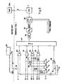
- Fig. 8 is a block diagram showing the overall electrical structure of the present downhole apparatus 1;
- FIG. 9 is a circuit diagram partly in blocks showing the electrical structure of the present downhole apparatus 1 more in detail;
- Fig. 10 is a circuit diagram showing the reset stabilized offset operational amplifier which is advantageously applied to the electrical structure of the present downhole apparatus 1;
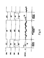
- Fig. 11 is a timing chart which is useful for explaining the operation of the reset stabilized operational amplifier shown in Fig. 10;
- Figs. 12, 13 and 14a through 14e are schematic illustrations which are useful for explaining the six step measurement cycle caried out by the present downhole apparatus 1;
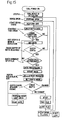
- Fig. 15 is a flow chart showing the overall sequence of operation which may be carried out by the present downhole apparatus 1; and
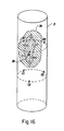
- Fig. 16 is a schematic illustration showing how the two dimensional survey for determination of the position of localized corrosion can be carried out by the multi-electrode scheme of the present downhole apparatus.
- a casing diagnostic downhole apparatus 1 constructed in accordance with one embodiment of the present invention.
- a borehole casing 3 extends into the earth 2, and the downhole apparatus 1 having a generally torpedo shape is fitted into the casing 3 as suspended by a cable 4.
- the cable 4 is a composite cable including a plurality of conductors, each of which is clad with an insulating material, and a high strength wire.
- the cable 4 extends upward and it is connected to a surface processing unit (not shown) located at the ground surface.
- the downhole apparatus 1 includes a plurality of sections along its longitudinal axis.
- the downhole apparatus 1 includes a head 5 at its top, to which the cable 4 is mechanically coupled, and a mass isolation adapter 6 which electrically isolates the downhole apparatus 1 from the cable 4 thereby preventing any possible galvanic coupling between the downhole apparatus 1 and the cable 4 or the downhole apparatus 1 and the casing 3 if the cable 4 touches the casing 3.
- the downhole apparatus 1 also includes a telemetry communication cartridge 7 next to the mass isolation adapter 6.
- the telemetry communication cartridge 7 is electrically connected to the surface unit (not shown) at the ground surface through the cable so as to carry out communication between the downhole apparatus 1 and the surface unit.
- the downhole apparatus 1 also includes an electronics cartridge 8 and a preamplifier electronics module 9, which include various electronics and electrical elements to define a measurement unit which directly measures desired electrical properties as will be described more in detail later. It will be sufficient to note in passing that measured analog data are processed and coverted into digital data which are then transmitted upward to the surface unit (not shown) from the telemetry communication cartridge 7 through the cable 4.
- an arm actuator section 10 which includes four identical arm assemblies 12a, 12b, 12c and 12d disposed at four different axial locations as equally spaced apart from each other over a distance L. Since these arm assemblies 12a, 12b, 12c and 12d are identical in structure, a description will be made only with respect to the top arm assembly 12a with assignment of identical numerals with different small English letters indicating different levels.
- the distance L is set approximately at 2 feet (0.6 meters), though the present invention should not be limited only to this particular distance.
- each arm assembly for example 12a, includes three arm sub-assemblies 12a1, 12a2 and 12a3 which are arranged in the circumferential direction at the same axial position and which may pivot radially between a retracted position where the arm sub-assemblies, e.g., 12a1, 12a2 and 12a3 are fit into respective recesses defined in the housing of the downhole apparatus 1 as shown in Fig.
- Fig. 1a shows a closed condition with all of the electrodes A through D located closer to the downhole apparatus 1 at the retracted position as contained in respective recesses defined therein thereby allowing the downhole apparatus 1 to be moved along the casing 3 vertically; on the other hand, Fig.
- each of the arm assemblies 12a, 12b, 12c and 12d includes spring means which normally biases the associated arm assembly so as to provide an inclination to take the advanced position as will be described later. It should further be noted that even if the downhole apparatus 1 is set in the open state as shown in Fig. 1b, the downhole apparatus 1 may be moved vertically along the casing 3 with the electrodes A through D sliding along the inner surface of the casing 3, if desired.
- the arm actuator section 10 also includes four driver shafts 14a, 14b, 14c and 14d which are operatively coupled to hydraulic jacks 13a, 13b, 13c and 13d, respectively.
- these hydraulic jacks 13a through 13d are hydraulically connected to a hydraulic control unit, including a motor, a pump, etc., disposed inside of a hydraulic power section 11 provided at the bottom of the downhole apparatus 1 through a hydraulic line which runs along the arm actuator section 10 from the hdyraulic power section 11.
- the hydraulic power section 11 is also operatively connected to the electronics cartridge 8 so that the activation and deactivation of the hydraulic power is controlled in accordance with a control signal supplied from the surface unit at the ground surface through the cable 4.
- the arm asembly 12a includes three identical arm sub-assemblies 12a1, 12a2 and 12a3 which are arranged in the circumferential direction at equal angular intervals, i.e., 120°, around the longitudinal centerline of the downhole apparatus 1. Since the arm sub-assemblies 12a1, 12a2 and 12a3 are identical in structure, only the arm sub-assembly 12a1 will be described in detail below.
- the arm sub-assembly 12a1 includes a pair of longer follower arms 20a1, 20a1, which are pivoted to a housing or body 1a of the downhole apparatus 1 at pivots 21a1, 21a1, respectively, a short follower arm 22a1 and a short driver arm 22a1 ⁇ , which are pivoted to the housing 1a at pivots 23a1, 23a1, respectively, and an electrode support plate 24a1 which is pivotally connected to the forward ends of the follower and driver arms 20a1, 22a1 and 22a1 ⁇ at pivots 25a1, 26a1 and 26a1, respectively.
- the electrode support plate 24a1 Since the pivots 21a1, 23a1, 25a1 and 26a1 together define a parallelogram, the electrode support plate 24a1 is so supported to be always in parallel with the longitudinal axis of the downhole apparatus 1 even if the follower and drive arms 20a1, 22a1 and 22a1 ⁇ pivot around the pivots 21a1 and 23a1 in unison. As will be described more in detail later, the electrode support plate 24a1 supports the corresponding electrode A1 so as to project radially outwardly, and, thus, the top surface of the electrode A1 supported by the support plate 24a1 comes into contact with the internal peripheral surface of the casing 3 when the arm assembly 12a is set in its advanced position.
- the follower arms 20a1 and 22a1 are simply elongated in shape, but the driver arm 22a1 ⁇ is generally L-shaped and it is pivoted to the body 1a of the downhole apparatus 1 its angled section.
- the forward end of the L-shaped driver arm 22a1 ⁇ is pivotally connected to the electrode support plate 24a1, but the other forward end is in engagement with a circular projection 15a which is integrally formed on the driver shaft 14a.
- the hydraulic jack 13a is fixedly mounted on the housing 1a which partly receives therein the driver shaft 14a whose forward end is slidably received in a guide hole 16a which is defined in the housing 1a.
- the driver shaft 14a projects outward so that the driver arm 22a1 ⁇ is forced to pivot clockwise around the pivots 23a1 in Fig. 2 thereby bringing the arm sub-assembly 12a1 and thus the electrode A1 into its retracted position shown in Fig. 3.
- the arm sub-assembly 12a1 also includes a composite leaf spring 27a1 whose base end is fixedly attached to the housing 1a by means of fixing means 28a1 and whose forward end is pivotally connected to the electrode support plate 24a1 through a connector 29a1, to which a roller 30a1 is rotatably mounted.
- Fig. 1b shows the condition in which all of the arm assemblies 12a through 12d are forced to move radially outward under spring force so that the electrodes A through D are all pressed against the internal peripheral surface of the casing 3.
- the housing 1a of the downhole apparatus 1 is provided with three recesses arranged in the circumferential direction at equal angular intervals corresponding in position to the associated arm sub-assemblies, e.g., 12a1, 12a2 and 12a3, so that these arm sub-assemblies may be received in the respective recesses when set in the retracted position as shown in Figs. 3 and 4.
- the arm sub-assemblies are all set in the retracted position, all of the electrodes A through D are located radially inward with respect to the outermost peripheral point of the housing 1a so that the electrodes A through D are prevented from coming into engagement with undesired objects unintentionally.
- the long arms 20a1 are located inward of the short arms 22a1 so that they are prevented from interfering pivotal motion from each other.
- the housing 1a is formed with a pair of holes 1b, 1b, in which the pivots 21a1, 21a1 are fitted, and a pair of holes 1c, 1c, in which the pivots 23a1, 23a1 are fitted.
- Fig. 7 shows in block diagram the hydraulic connection between the arm actuator section 10 and the hydraulic power section 11.
- the hydraulic power section 11 includes a reservoir 40 for storing there a quantity of working fluid, such as oil, and a safety valve 41 connected to the reservoir 40.
- a pump motor 42 Also provided in the hdyraulic power section 11 as being in fluidic communication with the reservoir 40 are a pump motor 42, a relief valve 44, a solenoid valve 45, a control valve 46 and a pressure switch 47.
- a check valve 43 is also provided as connected to the outlet of the pump motor 12.
- the pump motor 42 when the pump motor 42 is activated, the oil in the reservoir 40 is supplied under pressure to each of the jacks 13a through 13d in the arm actuator section 10, and, thus, the arm assemblies 12a through 12d are set in the closed condition as described before.
- the solenoid valve 45 when the solenoid valve 45 is opened, i.e., deactivating the hydraulic power section 11, the oil is returned to the reservoir 40 from the arm actuator section 10 under the recovery force of the springs 27.
- the operation of the arm assemblies 12a through 12d has been carried out hydraurically; however, it can also be done mechanically, electrically or magnetically as is obvious for one skilled in the art.
- Figs. 6a through 6d show an electrode assembly which can be advantageously applied to the above-described downhole apparatus 1.
- the electrode assembly has an enclosed structure and it includes a base 31, for example, of steel generally in the shape of a plate with its top central portion recessed.
- a bottom insulator 34 of, preferably, PEEK (Poly-Ether-Ether-Ketone) is placed on the top surface of the base 31, and then an ax-shaped electrode 32 having a triangular top surface 32a sits on the bottom insulator 34 so that the electrode 35 is electrically isolated from the steel base 31.
- PEEK Poly-Ether-Ether-Ketone
- the electrode 35 is coated with an electrically insulating material, preferably Viton.
- the electrode 32 is integrally provided with a socket connector on which a rubber boot 33 is fitted.
- the electrode 32 is electrically connected to the electrical circuit formed in the electronics cartridge and preamplifier electronics sections 8 and 9 through the socket connector and interconnection lines (not shown).
- a packer 35 of, preferably, Viton which encloses the ax-shaped electrode 32.
- the packer 35 has a truncated pyramid shape and it is formed with a slit 35a at its top flat surface, so that the apex surface 32a of the ax-shaped electrode 32 can come into contact with the internal peripheral surface of the casing 3 through the slit 35a when the electrode 32 is located at its advanced position to be pressed against the casing 3.
- a pair of covers 37 and 36 of, preferably, PEEK, are placed on the connector and electrode sections, respectively, as shown, and these covers 37 and 36 are fixedly attached to the base 31 by means of screws 38 which are screwed into threaded holes (not shown) formed in the base 31 through the holes 34a formed in the bottom insulator 34.
- the electrode 32 is enclosed by an electrically insulating material excepting a predetermined section, i.e., apex surface 32a in the illustrated embodiment, which may be exposed through the slit 35a when the electrode 32 is pressed against the casing 3.
- the electrode 32 is coated with an insulating material and enclosed in the packer 35.
- the packer 35 may be molded on the electrode 35 with or without coating. Alternatively, the electrode 35 may be simply placed in the packer 35 without coating, if desired.
- its apex surface 32a may also be coated because the coating on the apex surface 32a may be removed when the electrode 32 is first pressed against the casing 3. However, it is true that it is preferable to provide no coating on the apex surface 32a.
- FIG. 8 there are shown 8 electrodes A, B1-B3, C1-C3 and D.
- A refers to the topmost stage
- B to the second highest stage
- C to the third highest stage
- D to the bottom stage.
- the present embodiment includes three electrodes circumferentially arranged at each stage, i.e., A1-A3, B1-B3, C1-C3 and D1-D3.
- the three electrodes of each of the top and bottom stages, i.e., A1-A3 and D1-D3, are all shorted together.
- each of the identical amplifier circuits 51 through 54 has a two-stage structure comprised of a preamplifier and main amplifier which are basically the same in structure and include a reset stabilized operational amplifier, which will be described in detail later.
- the preamplifier section which is the first half of each of the amplifier circuits 51 through 54, is positioned in the preamplifier electronics section 9 and the other half is positiond in the electronics cartridge section 8. Since each of the amplifier circuits 51 through 54 is connected to a corresponding pair of electrodes, potential difference, present across the corresponding pair of electrodes when pressed against the casing 3 can be directly measured by the amplifier circuits 51 through 54.
- All of the four amplifier circuits 51 through 54 have their output terminals connected to a multiplexer 57.
- another amplifier circuit 55 which is of conventional design since high accuracy is not necessary for this amplifier.
- the amplifier circuit 55 has two input terminals, across which is provided a resistor R, and an output terminal which is connected to the multiplexer 57.
- a current source 56 is provided and is connected to one end of the resistor R and this supplies known currents to selected pairs of electrodes when contact resistance between the electrodes and the casing 3 or casing resistance is to be measured.
- the multiplexer 57 has its output terminal connected to an analog-to-digital (A/D) converter 59 through an auto-gain ranger 58, which allows signals of very different levels due to the different measuring modes in each of the steps of the measurement cycle to be digitized by the same circuitry for a given gain depending on the signal level.
- the A/D converter 59 is connected through a bus to a downhole tool bus interface (DTB I/F) 60 which is also connected to a control logic 61.
- DTB I/F 60 is connected to a telemetry communication cartridge 7 which is also connected to a power supply 62 in the electronics cartridge section 8 and to a surface processing unit 50, typically including a computer, at the ground surface through the cable 4.
- the computer in the surface unit 50 sends commands to the control logic 61 in the electronics cartridge section 8 through the cable 4 and telemetry system, which then supplies various control signals to various elements in the electronics cartridge section 8 to control the various steps in a measurement cycle.
- the power required to operate various electronics elements is also supplied from the surface unit 50 through the power supply 62.
- the potential difference present across two pairs of electrodes in contact with the casing 3 is directly measured in the form of an analog signal and amplified by the corresponding amplifier circuit 51, 52, 53 or 54, and this signal is converted into digital data, which is then transmitted to the surface unit 50 through the cable 4.
- a reset stabilized amplifier having a feedback loop enables the signal to be digitized with high accuracy as the signal then covers the dynamic range of the amplifier, thereby allowing the efficient use of the number of bits to be provided by the A/D converter 59.
- the offset of an amplifier due to temperature variation can be effectively eliminated by a reset stabilized amplifier structure as will be described below.
- Fig. 10 shows a reset stabilized operational amplifier when used as the first stage of each of the two-stage amplifier circuits 51 through 54, and it includes a main d.c. amplifier A1, which has a pair of first input terminals, a second input terminal and an output terminal.
- the pair of first input terminals of the amplifier A1 is connected to a corresponding pair of electrodes X and Y (in the illustrated example, X-Y corresponds to any pair of B1-C1, B2-C2, B3-C3 and A-D) through a pair of input switches SW1 which are turned on and off together as indicated by the dotted line.
- the pair of first input terminals of the amplifier A1 is also connected to reference, ususally ground, through another pair of reset switches SW2 which are also operated together.
- the amplifier A1 supplies its output from its output terminal which is connected to an input terminal (or non-inverting input terminal) of the main d.c. amplifier of the second stage and which is also connected to the second input terminal of the amplifier A1 via a negative feedback loop, as shown in Fig. 10.
- the feedback loop includes, as connected in series from the output terminal of the amplifier A1 to the second input terminal of the amplifier A1, a sampling switch SW3 for sampling an offset voltage produced by the main d.c. amplifier A1 at its output terminal, an amplifier A2 for detecting and amplifying the offset voltage sampled by the sampling switch SW3, a holding switch SW4, and a holding amplifier A3.
- Two capacitors C1 and C2 are also provided and are connected in series at the input and output terminals of the amplifier A2, respectively. These capacitors are required in order to eliminate the offset voltage of the amplifier A2.
- C1, C2 and A2 together constitute an a.c. offset amplifier.
- a holding capacitor C H is provided as connected between the input terminal of the holding amplifier A3 and ground.
- the holding capacitor C H temporarily holds the offset voltage from the main d.c. amplifier A1 after it has been amplified by the a.c. offset amplifier comprised of C1, C2 and A2 for a period between the on and off operation of the holding switch SW4.
- the offset voltage temporarily stored in the holding capacitor C H is applied to the second input terminal of the main d.c. amplifier A1 through the holding amplifier A3 which serves as a buffer for this voltage.
- an electrical property measured across the pair of electrodes X and Y along the casing 3 can be amplified by the main d.c. amplifier A1 and supplied as its output without including the amplifier offset voltage because it is effectively cancelled at the amplifier A1.
- Fig. 11 it will be described as to how the reset stabilized operational amplifier shown in Fig. 10 operates to measure a desired electrical property present across the pair of electrodes X and Y along the casing 3 without being adversely affected by the offset voltage of the main d.c. amplifier A1.
- the reference characters indicated in the left side column correspond to those elements having identical reference characters in the circuit of Fig. 10.
- the switches SW1, SW3 and SW4 are all off and the switches SW2 are on, so that the pair of first input terminals of the amplifier A1 is grounded.
- the main d.c. amplifier A1 supplies at its output terminal an offset voltage h1.
- this offset voltage h1 is sampled and amplified by the amplifier A2, and, shortly thereafter the holding switch SW4 is turned on and the holding capacitor C H is charged by the offset voltage thus amplified.
- this offset voltage is fed back to the second input terminal of the amplifier A1 through the amplifier A3. Since this fed back offset voltage is applied to the second input terminal of the amplifier A1 in a negative sense, the original offset voltage h1 is reduced.
- the holding switch SW4 is turned off, so that the amplifier A3 continues to apply the offset voltage stored in the holding capacitor C H for a time period until the holding switch SW4 is next turned on. In succession, the sampling switch SW3 is turned off.
- Fig. 9 shows the electrical structure of the present downhole apparatus 1, which is basically the same as Fig. 8 but is more detailed particularly with respect to the structure of the current source 56.
- the current source 56 of Fig. 8 in fact, includes four current sources I1 through I4.
- a digitization unit 63 at the ground surface is also shown in Fig. 9 as connected to the downhole apparatus 1 through the cable 4.
- the current sources I1 through I3 are identical and they supply a current equal to 1 mA; whereas, the current source I4 supplies a larger current equal to 0.5 A.
- the exact value of the currents is not important and could be changed without altering the functioning of the apparatus. What is important is that one is relatively small as compared with the other.
- the current source I1 is so connected that it supplies a small current of 1 mA across the pair of electrodes B1 and C1 along the casing 3 when a pair of switches S1, S1, which are operated together as indicated by the connecting dotted line, is closed and a switch S13 is closed.
- This corresponds to injection of a small axial current along the casing 3 between the two electrodes B1 and C1 which are arranged in the longitudinal direction.
- switches S12 and S13 are in operative association as they are connected by the dotted line so that when the switch S13 is closed, the switch S12 is open and when the switch S13 is open, the switch S12 is closed.
- the current source I1 supplies a current of 1 mA across the pair of electrodes B1 and B2 along the casing 3. This corresponds to injection of a small current in the circumferential direction on the casing 3 because the electrodes B1 and B2 are located at the same axial position.
- the current source I2 supplies a current of 1 mA across the pair of electrodes B2 and C2 along the casing 3.
- switches S14 and S15 are operated at the same time such that one of them is open and the other closed, and, thus, if the switch S14 is open and thus the switch S15 is closed when a pair of switches S3, S3 is closed, the current source I3 supplies its current of 1 mA across the electrodes B3 and C3 along the casing 3 in the longitudinal direction thereof; whereas, if the switch S14 is closed and thus the switch S15 is open when the switches S3, S3 are closed, the current supplied by the current source I3 flows across the two electrodes C2 and C3 along the casing 3 circumferentially.
- the amplifier circuit 51 which contains two stages of a reset stabilized operational amplifier as described above, has its inverting input terminal connected to the electrode B1 at the second highest axial position and its non-inverting input terminal connected to a switch S9.
- the switch S9 when the switch S9 is off, it causes the non-inverting input terminal of the amplifier 51 to be connected to the electrode C1 at the third highest axial position; on the other hand, when the switch S9 is on, the non-inverting input terminal of the amplifier 51 is connected to the electrode B2 at the second highest axial position.
- a switch S10 is operatively associated with the switch S9, and the inverting input terminal of the third amplifier circuit 53 is connected to the electrode B3 when the switch S10 is off and to the electrode C2 when the switch S10 is on while the non-inverting input terminal of the amplifier circuit 53 is always connected to the electrode C3.
- the second amplifier circuit 52 has its non-inverting and inverting input terminals connected to and disconnected from the respective electrodes B2 and C2 depending on as to whether its pair of switches S11, S11 is on or off, respectively.
- the fourth amplifier circuit 54 has its inverting input terminal connected to the electrode A, which is a combination of three electrodes A1-A3 shorted together, and also to the surface digitization unit 63 through a switch S6 and the cable 4.
- the non-inverting input terminal of the fourth amplifier circuit 54 is connected to the electrode D, which is also a combination of three electrodes D1-D3 shorted together.
- the current source I4, which supplies the large current of 0.5 A, is connected in series with the resistor R and it supplies the current of 0.5 A across the top and bottom electrodes A and D along the casing 3 when a pair of switches S4, S4 is closed. As shown in Fig.
- the surface unit includes a digitising unit 63 which has a pair of input terminals one of which connects to a reference potential source REF1 and the other to S6 via the cable 4. It is to be noted that the surface unit also includes a telemetry communication module 50a which is mounted in the surface unit 50 for communication with the telemetry cartridge 7 of the downhole apparatus 1. It should also be understood that all of the switches S1 through S4, S6 and S9 through S15 are operated by control signals supplied from the control logic 61 to which commands are supplied from the surface unit 50 via the cable 4.
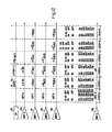
- Figs. 12, 13, 14a through 14f and 15 potential differences in the axial and circumferential directions between two points on the casing 3, casing resistances in the axial direction between two points on the casing 3 and contact resistances between the electrodes B, C and the casing 3 are measured as selected electrical properties in a six step measurement cycle.
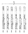
- the six step cycle includes STEP0 through STEP5 as indicated in Figs. 12 and 13, and, more particularly in Figs. 14a through 14f.
- Fig. 15 shows the overall sequence of steps in the measurement operation.
- the measurement operation is triggered and controlled by the software stored in a computer system (not shown) in the surface unit 50 at the ground surface.
- a computer system not shown
- the software is continually checking the depth.
- the software sees a constant depth for longer than a predetermined period, it triggers the start of the six step measurement cycle.
- the software rings a bell to indicate that the six step measurement cycle is complete and that the downhole apparatus 1 can be moved to another depth.
- the surface unit 50 also includes a printer which prints out the measured results every time upon completion of the six step measurement cycle, and the printer also prints out a GOOD/BAD electrode contact condition for the contact resistance measurements based on an upper limit which has been selectively determined by the operator prior to the operation. Such an upper limit may be refined based on the data just taken. Accordingly, the operator at the ground surface knows when he can move the downhole apparatus 1 to another depth whenever the bell rings, and the operator has an immediate indication of whether the data is good or bad according to the contact resistance information. Once the software has finished the data acquisition, computation, rung the bell and printed out the results, it again starts to check the depth pulses. Once it sees a change in depth, it then goes to the depth checking routine thereby looking for a cessation of depth pulses, which indicates that the downhole apparatus 1 has been located at another depth.
- the data collected is screened based on the contact resistance data between the electrodes and the casing, and those data, for which the contact resistance data is found to be equal to or smaller than a derived reference value, are extracted as valid data for use in data processing. That is, if a metal casing is corroded, a corroded layer is usually formed on the surface of the casing at least partly. Thus, even if an electrode is pressed against the casing, it may be that the electrode is not brought into electrical contact with the casing per se properly due to the presence of a relatively thick corroded layer. In such a case, the contact resistance between the electrode and the casing is relatively high, so that accurate measurements of desired electrical properties, such as a potential difference between two points on the casing are hindered.
- the contact resistance is lower than this upper limit, the potential drop across teh contact resistance can be considered to be negligible and thus the potential difference measured across two electrodes pressed against the casing is substantially equal to the real potential difference existing along the casing between the two corresponding points. Therefore, it is important to measure the contact resistance as a quality control of the data taken and to indicate a GOOD/BAD contact condition to the operator. A more detailed explanation in this respect is found in the beofer-mentioned Japanese Patent Application, No. 60-244217.
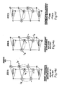
- Figs. 14a through 14f correspond to the respective steps in the six step measurement cycle which includes:
- the present downhole apparatus 1 includes three circumferentially arranged electrodes at four different axial levels. But, the electrodes A1-A3 at the top level are always shorted together and the electrodes D1-D3 are always shorted together in the present embodiment, so that there are, in effect, 8 electrodes which are electrically isolated from each other. It is to be noted that the all of the electrodes A-D are in contact with the inner peripheral surface of the casing 3 in Figs. 14a through 14f. In Fig. 12, the ON/OFF condition of each of the switches S1 through S4, S6 and S9 through S15 shown in Fig.
- Fig. 13 shows a stream of data supplied from the A/D converter 59 eventually to the surface unit 50 through the cable 4 in each of the six steps STEP0 through STEP5.
- each of the five amplifier circuits 51 through 54 are shorted and commonly connected to ground. This corresponds to the case in which the switches SW1, SW1 are turned off and the switches SW2, SW2 are turned on in the circuit of Fig. 10.
- the amplifier circuits 51 through 54 supply their offset values OUT1 through OUT 5 which are then supplied to the surface unit 50 through the cable 4 after having been digitized by the A/D converter 59.
- the switches S1 through S4 and S6 through S15 are set as indicated in the STEP1 column of Fig. 12 so that an electrical connection is established such that the first amplifier circuit 51 measures a potential difference between the electrodes B1 and C1, the second amplifier circuit 52 measures a potential difference between the electrodes B2 and C2, the third amplifier circuit 53 measures a potential difference between the electrodes B3 and C3, and the fourth amplifier circuit 54 measures a potential difference between the electrodes A and D.
- the two electrodes, across which an axial potential difference is measured are circled and connected by a dotted curve line.
- the four potential difference data are taken, digitized by the A/D converter 59 and transmitted to the surface unit 50 in the form of a data stream shown at STEP1 in Fig. 13.
- the switches S4 in Fig. 9 are turned on so that the known current I0, or 0.5 A in the present embodiment, is applied between the top and bottom electrodes A and D by the current source I4.
- the injection of this current I0 is indicated by the arrow directed to the electrode A1.
- the potential differences across the three pairs of vertically oriented electrodes B1-C1, B2-C2, and B3-C3 are measured thereby allowing to calculate three casing resistances.
- the contact resistance between the top and bottom electrodes A and D and the casing 3 can be determined.
- the measured potential differences for use in calculation of casing resistances are indicated by single prime and the measured potential differences for use in calculation of contact resistances are indicated by double prime.
- the switches S1, S2 and S3 shown in Fig. 9 are all turned on so that the current sources I1 through I3 supply a small known current of 1 mA to the respective pairs of electrodes B1-C1, B2-C2 and B3-C3.
- the injection of these small currents are indicated by the arrows in Fig. 14d.
- the potential differences between the respective pairs of electrodes are measured, which are digitized and supplied to the surface unit 50 where the data is processed to calculate contact resistances.
- the switch S6 since the switch S6 is turned on and the potential difference between the electrode A and the surface reference is measured by the surface digitizing unit.
- the switches S9 and S10 are turned on and the switches S11 are turned off with the switches S1 and S3 turned on so that the first amplifier circuit 51 is connected to measure a potential difference between the two electrodes B1 and B2 in the same and second-level circumference and the third amplifier circuit 53 is connected to measure a potential difference between the two electrodes C2 and C3 at the same and third-level circumference.
- the small current of 1 mA is injected to flow along two circumferential paths on the casing 3.
- the circumferential potential difference is measued between the electrodes B1-B2 and also between C2-C3, and the thus measured results are digitized and transmitted to the surface unit 50, where calculation is carried out to obtain the contact resistances between the electrodes B1-B2 and the casing 3 and between the electrodes C2-C3 and the casing 3.
- the small current I5, actually I1 and I3 injected at this step shown in Fig. 14e is 1 mA in the present embodiment.
- the switches S1 and S3 shown in Fig. 9 are turned off thereby terminating the injection of the small currents, and the first and third amplifier circuits 51 and 53 are connected to measure a potential difference between the electrodes B1 and B2 and between the electrodes C2 and C3, as indicated in Fig. 14f.
- the potential difference measurements are carried out between B1 and B2 and between C2 and C3 and the measured results are digitized and transmitted to the surface unit 50 thereby completing the six step measurement cycle.
- Fig. 16 shows a section of the casing 3 in which a cathodic area 3a and an anodic area 3b are formed locally.
- the points of contact by the three second-level electrodes B1-B3 and third-level electrodes C1-C3 are indicated by crosses. It is seen that the electrode B2 is located in the anodic area 3b with the other electrodes being not located in either of the cathodic and anodic areas 3a and 3b.
- the direction of the localized current flowing in the metal of the casing 3 from the cathodic area 3a to the anodic area 3b is indicated by the white arrows. Thus, net current will leave the casing 3 from the anodic area 3b to the surrounding earth.
- the present invention allows to pin-point the location of the corrosion because the axial potential difference between B2-C2 will be different from those between B1-C1 and B3-C3 and the circumferential potential difference between B2-B1 of B2-B3 will be different from any between C2-C1, C2-C3 or C1-C3.
- the resolution in the axial and circumferential directions is enhanced as the number of electrodes provided is increased.
- four or more electrodes are disposed axially or circumferentially because such an arrangement will allow to measure a casing resistance between two inner electrodes with the two outer electrodes injecting a known current.
- the downhole apparatus when the downhole apparatus is so structured to measure a desired electrical property at the site of deployment directly, measurements can be carried out at high accuracy. Since the measurements are carried out locally and the measured results are digitized and transmitted to a desired place through the cable, the measurements are not adversely affected by the cable no matter how long it may be.
- the downhole apparatus is structured to have a plurality of electrodes arranged axially as well as circumferentially, a local two dimensional survey of the casing 3 can be carried out at the same time, which allows to determine the location of possible corrosion more accurately, at high resolution and at high speed.
- the present invention may be so structured to transmit amplified data to ground surface in an analog form through the cable 4.
- the A/D converter 59 may be discarded.
- the present invention may also be so structured that multiplexing takes place before amplification. In this case, only one ammplifier is required.
Landscapes
- Life Sciences & Earth Sciences (AREA)
- Engineering & Computer Science (AREA)
- Physics & Mathematics (AREA)
- Geology (AREA)
- Mining & Mineral Resources (AREA)
- Environmental & Geological Engineering (AREA)
- Geochemistry & Mineralogy (AREA)
- Fluid Mechanics (AREA)
- General Life Sciences & Earth Sciences (AREA)
- Environmental Sciences (AREA)
- Biochemistry (AREA)
- Ecology (AREA)
- Mechanical Engineering (AREA)
- Health & Medical Sciences (AREA)
- Chemical & Material Sciences (AREA)
- Analytical Chemistry (AREA)
- Biodiversity & Conservation Biology (AREA)
- General Health & Medical Sciences (AREA)
- General Physics & Mathematics (AREA)
- Immunology (AREA)
- Pathology (AREA)
- Geophysics (AREA)
- Geophysics And Detection Of Objects (AREA)
- Investigating Or Analyzing Materials By The Use Of Electric Means (AREA)
Applications Claiming Priority (2)
| Application Number | Priority Date | Filing Date | Title |
|---|---|---|---|
| JP60299777A JPS62159038A (ja) | 1985-12-30 | 1985-12-30 | 穿孔ケ−シング診断装置 |
| JP299777/85 | 1985-12-30 |
Publications (3)
| Publication Number | Publication Date |
|---|---|
| EP0235478A2 true EP0235478A2 (de) | 1987-09-09 |
| EP0235478A3 EP0235478A3 (en) | 1989-10-25 |
| EP0235478B1 EP0235478B1 (de) | 1993-11-24 |
Family
ID=17876829
Family Applications (1)
| Application Number | Title | Priority Date | Filing Date |
|---|---|---|---|
| EP86402878A Expired - Lifetime EP0235478B1 (de) | 1985-12-30 | 1986-12-19 | Prüfvorrichtung für Bohrlochverrohrungen |
Country Status (3)
| Country | Link |
|---|---|
| EP (1) | EP0235478B1 (de) |
| JP (1) | JPS62159038A (de) |
| DE (1) | DE3689332D1 (de) |
Cited By (11)
| Publication number | Priority date | Publication date | Assignee | Title |
|---|---|---|---|---|
| FR2610728A1 (fr) * | 1987-02-05 | 1988-08-12 | Chevron Res | Appareil et procede de determination de la resistance electrique dans un element metallique tubulaire notamment un tubage de puits |
| EP0651132A3 (de) * | 1993-11-01 | 1995-08-09 | Halliburton Co | Verfahren zur Ortung von Ruhrverbindungen im Bohrloch. |
| EP0697497A1 (de) * | 1994-08-18 | 1996-02-21 | Halliburton Company | Vorrichtung zum Lokalisieren von Verbindungen im Bohrloch |
| GB2420856A (en) * | 2004-12-03 | 2006-06-07 | Capcis Ltd | Downhole corrosion monitor |
| US7317308B2 (en) | 2005-01-27 | 2008-01-08 | Shell Oil Company | System and method for measuring electric current in a pipeline |
| US7821247B2 (en) | 2005-01-27 | 2010-10-26 | Shell Oil Company | System and method for measuring electric current in a pipeline |
| CN102645155A (zh) * | 2011-02-18 | 2012-08-22 | 韩国地质资源研究院 | 用于检测目标区域的结构稳定性的方法和设备 |
| US10781687B2 (en) | 2015-12-16 | 2020-09-22 | Halliburton Energy Services, Inc. | Electrical impedance tomography using a switchable array |
| US11326437B2 (en) * | 2013-06-12 | 2022-05-10 | Well Resolutions Technology | Universal bottomhole assembly node (UBHAN) providing communications to and from rotary steerable systems (RSS) and real time azimuthal resistivity imaging for geosteering and pressure while drilling (FWD) for well control |
| CN115112724A (zh) * | 2022-06-30 | 2022-09-27 | 中国地质科学院 | 一种管道内壁涂层的检测装置及其检测方法 |
| CN115950929A (zh) * | 2022-12-29 | 2023-04-11 | 国家石油天然气管网集团有限公司 | 一种用于dcvg检测和cips检测的智能探仗 |
Families Citing this family (7)
| Publication number | Priority date | Publication date | Assignee | Title |
|---|---|---|---|---|
| JP2561286B2 (ja) * | 1987-07-24 | 1996-12-04 | 大阪瓦斯株式会社 | 地中埋設金属管の補修方法 |
| US7104147B2 (en) | 2004-01-30 | 2006-09-12 | Shell Oil Company | System and method for measuring electric current in a pipeline |
| JP5078964B2 (ja) * | 2009-09-18 | 2012-11-21 | 報国エンジニアリング株式会社 | 地下水位の測定方法 |
| JP6274583B2 (ja) * | 2015-06-29 | 2018-02-07 | 株式会社福田組 | 電気探査方法 |
| JP7082955B2 (ja) * | 2019-04-22 | 2022-06-09 | 東急建設株式会社 | サンプリングモールド及び土の非破壊物性測定方法 |
| DE102021113965A1 (de) * | 2021-05-31 | 2022-12-01 | Rwe Gas Storage West Gmbh | Messvorrichtung für eine Rohrtour einer Tiefenbohrung |
| CN114135270A (zh) * | 2021-11-19 | 2022-03-04 | 傅宇涵 | 一种石油及天然气开采井下测井仪 |
Citations (1)
| Publication number | Priority date | Publication date | Assignee | Title |
|---|---|---|---|---|
| US3207981A (en) | 1960-11-21 | 1965-09-21 | Pure Oil Co | Electrical device having uniquely posi-tioned electrodes for determining metal loss from tubular members |
Family Cites Families (4)
| Publication number | Priority date | Publication date | Assignee | Title |
|---|---|---|---|---|
| US3167707A (en) * | 1960-12-29 | 1965-01-26 | Seismograph Service Corp | Well logging apparatus having laterally shiftable wall engageable electrode supports |
| FR1549531A (de) * | 1967-11-02 | 1968-12-13 | Schlumberger Prospection | |
| US3568053A (en) * | 1968-10-15 | 1971-03-02 | Sinclair Oil Corp | Apparatus for establishing electrical contact with the casing in a wellbore |
| US4431964A (en) * | 1981-09-28 | 1984-02-14 | Dresser Industries, Inc. | Method for determining a natural current flow in well casing |
-
1985
- 1985-12-30 JP JP60299777A patent/JPS62159038A/ja active Granted
-
1986
- 1986-12-19 DE DE86402878T patent/DE3689332D1/de not_active Expired - Lifetime
- 1986-12-19 EP EP86402878A patent/EP0235478B1/de not_active Expired - Lifetime
Patent Citations (1)
| Publication number | Priority date | Publication date | Assignee | Title |
|---|---|---|---|---|
| US3207981A (en) | 1960-11-21 | 1965-09-21 | Pure Oil Co | Electrical device having uniquely posi-tioned electrodes for determining metal loss from tubular members |
Cited By (15)
| Publication number | Priority date | Publication date | Assignee | Title |
|---|---|---|---|---|
| FR2610728A1 (fr) * | 1987-02-05 | 1988-08-12 | Chevron Res | Appareil et procede de determination de la resistance electrique dans un element metallique tubulaire notamment un tubage de puits |
| EP0651132A3 (de) * | 1993-11-01 | 1995-08-09 | Halliburton Co | Verfahren zur Ortung von Ruhrverbindungen im Bohrloch. |
| EP0697497A1 (de) * | 1994-08-18 | 1996-02-21 | Halliburton Company | Vorrichtung zum Lokalisieren von Verbindungen im Bohrloch |
| AU683381B2 (en) * | 1994-08-18 | 1997-11-06 | Halliburton Company | Slick line casing and tubing joint locator and associated methods |
| GB2420856B (en) * | 2004-12-03 | 2009-07-01 | Capcis Ltd | Measurement of corrosivity |
| GB2420856A (en) * | 2004-12-03 | 2006-06-07 | Capcis Ltd | Downhole corrosion monitor |
| US7317308B2 (en) | 2005-01-27 | 2008-01-08 | Shell Oil Company | System and method for measuring electric current in a pipeline |
| US7821247B2 (en) | 2005-01-27 | 2010-10-26 | Shell Oil Company | System and method for measuring electric current in a pipeline |
| CN102645155A (zh) * | 2011-02-18 | 2012-08-22 | 韩国地质资源研究院 | 用于检测目标区域的结构稳定性的方法和设备 |
| US11326437B2 (en) * | 2013-06-12 | 2022-05-10 | Well Resolutions Technology | Universal bottomhole assembly node (UBHAN) providing communications to and from rotary steerable systems (RSS) and real time azimuthal resistivity imaging for geosteering and pressure while drilling (FWD) for well control |
| US20220341310A1 (en) * | 2013-06-12 | 2022-10-27 | Well Resolutions Technology | Universal bottomhole assembly node (ubhan) |
| US12228027B2 (en) | 2013-06-12 | 2025-02-18 | Well Resolutions Technology | Universal bottomhole assembly node (UBHAN) |
| US10781687B2 (en) | 2015-12-16 | 2020-09-22 | Halliburton Energy Services, Inc. | Electrical impedance tomography using a switchable array |
| CN115112724A (zh) * | 2022-06-30 | 2022-09-27 | 中国地质科学院 | 一种管道内壁涂层的检测装置及其检测方法 |
| CN115950929A (zh) * | 2022-12-29 | 2023-04-11 | 国家石油天然气管网集团有限公司 | 一种用于dcvg检测和cips检测的智能探仗 |
Also Published As
| Publication number | Publication date |
|---|---|
| EP0235478B1 (de) | 1993-11-24 |
| EP0235478A3 (en) | 1989-10-25 |
| JPS62159038A (ja) | 1987-07-15 |
| JPH0556830B2 (de) | 1993-08-20 |
| DE3689332D1 (de) | 1994-01-05 |
Similar Documents
| Publication | Publication Date | Title |
|---|---|---|
| US4857831A (en) | Borehole casing diagnostic apparatus and method | |
| EP0235478B1 (de) | Prüfvorrichtung für Bohrlochverrohrungen | |
| EP1728103B1 (de) | System zur messung des spezifischen widerstands einer formation durch ein elektrisch leitfähiges bohrlochgehäuse hindurch | |
| US20050264295A1 (en) | System for measuring earth formation resistivity through an electrically conductive wellbore casing | |
| US7416023B2 (en) | Formation pressure testing apparatus with flexible member and method of formation pressure testing | |
| CA2161500C (en) | Method and apparatus for measuring mud resistivity in a wellbore including a probe having a bottom electrode located at the bottom of a tool string and propagating a current from and to the bottom electrode in a direction parallel to a longitudinal axis of the tool | |
| US9547100B2 (en) | Multi-array laterolog tools and methods with differential voltage measurements | |
| US8943884B2 (en) | Smart seals and other elastomer systems for health and pressure monitoring | |
| US4794322A (en) | Method, system, and tool for investigating borehole casings | |
| US4642570A (en) | Method and apparatus for complex resistivity measurements with elimination of electromagnetic coupling effects | |
| US4431963A (en) | Apparatus for determining a natural current flow in well casing | |
| EA011498B1 (ru) | Способ и устройство для повышения качества изображений толщи пород, получаемых по данным метода сопротивлений с помощью скважинных контактных приборов | |
| US11561319B2 (en) | Software tuning of borehole imagers | |
| US4431964A (en) | Method for determining a natural current flow in well casing | |
| EP0112248B1 (de) | Verfahren und Apparat zum elektrischen Feststellen der lichten Weite von Rohren | |
| RU2065957C1 (ru) | Способ измерения электрохимических свойств формаций, прилегающих к скважине | |
| US8925378B2 (en) | Modular apparatus and method for making measurements in boreholes | |
| US3065633A (en) | Well surveying apparatus | |
| CN1979221B (zh) | 用于通过导电井眼套管测量地球地层电阻率的系统 | |
| JPH06130158A (ja) | 高分解能検層方法及び装置 | |
| US12140724B2 (en) | Velocity correction with joint inversion | |
| US20230349285A1 (en) | Measuring water level in highly deviated or horizontal hydrocarbon well sections | |
| US11543555B2 (en) | Method to estimate formation resistivity | |
| SU1352045A1 (ru) | Устройство дл прив зки данных скважинного пробоотборника к геологическому разрезу | |
| MXPA01010730A (en) | A method and apparatus for determining the resistivity of a formation through which a cased well passes |
Legal Events
| Date | Code | Title | Description |
|---|---|---|---|
| PUAI | Public reference made under article 153(3) epc to a published international application that has entered the european phase |
Free format text: ORIGINAL CODE: 0009012 |
|
| AK | Designated contracting states |
Kind code of ref document: A2 Designated state(s): DE FR GB IT NL |
|
| PUAL | Search report despatched |
Free format text: ORIGINAL CODE: 0009013 |
|
| AK | Designated contracting states |
Kind code of ref document: A3 Designated state(s): DE FR GB IT NL |
|
| 17P | Request for examination filed |
Effective date: 19900409 |
|
| 17Q | First examination report despatched |
Effective date: 19910410 |
|
| GRAA | (expected) grant |
Free format text: ORIGINAL CODE: 0009210 |
|
| AK | Designated contracting states |
Kind code of ref document: B1 Designated state(s): DE FR GB IT NL |
|
| PG25 | Lapsed in a contracting state [announced via postgrant information from national office to epo] |
Ref country code: IT Free format text: LAPSE BECAUSE OF FAILURE TO SUBMIT A TRANSLATION OF THE DESCRIPTION OR TO PAY THE FEE WITHIN THE PRE;WARNING: LAPSES OF ITALIAN PATENTS WITH EFFECTIVE DATE BEFORE 2007 MAY HAVE OCCURRED AT ANY TIME BEFORE 2007. THE CORRECT EFFECTIVE DATE MAY BE DIFFERENT FROM THE ONE RECORDED.SCRIBED TIME-LIMIT Effective date: 19931124 Ref country code: NL Effective date: 19931124 Ref country code: DE Effective date: 19931124 |
|
| REF | Corresponds to: |
Ref document number: 3689332 Country of ref document: DE Date of ref document: 19940105 |
|
| ET | Fr: translation filed | ||
| NLV1 | Nl: lapsed or annulled due to failure to fulfill the requirements of art. 29p and 29m of the patents act | ||
| PLBE | No opposition filed within time limit |
Free format text: ORIGINAL CODE: 0009261 |
|
| STAA | Information on the status of an ep patent application or granted ep patent |
Free format text: STATUS: NO OPPOSITION FILED WITHIN TIME LIMIT |
|
| 26N | No opposition filed | ||
| REG | Reference to a national code |
Ref country code: GB Ref legal event code: IF02 |
|
| PGFP | Annual fee paid to national office [announced via postgrant information from national office to epo] |
Ref country code: FR Payment date: 20051208 Year of fee payment: 20 |
|
| PGFP | Annual fee paid to national office [announced via postgrant information from national office to epo] |
Ref country code: GB Payment date: 20051214 Year of fee payment: 20 |
|
| PG25 | Lapsed in a contracting state [announced via postgrant information from national office to epo] |
Ref country code: GB Free format text: LAPSE BECAUSE OF EXPIRATION OF PROTECTION Effective date: 20061218 |
|
| REG | Reference to a national code |
Ref country code: GB Ref legal event code: PE20 |