EP0234829B1 - Knife roll assembly for a meat tenderizer - Google Patents
Knife roll assembly for a meat tenderizer Download PDFInfo
- Publication number
- EP0234829B1 EP0234829B1 EP87301306A EP87301306A EP0234829B1 EP 0234829 B1 EP0234829 B1 EP 0234829B1 EP 87301306 A EP87301306 A EP 87301306A EP 87301306 A EP87301306 A EP 87301306A EP 0234829 B1 EP0234829 B1 EP 0234829B1
- Authority
- EP
- European Patent Office
- Prior art keywords
- blades
- blade
- module
- shaft
- knife
- Prior art date
- Legal status (The legal status is an assumption and is not a legal conclusion. Google has not performed a legal analysis and makes no representation as to the accuracy of the status listed.)
- Expired
Links
- 108010091431 meat tenderizer Proteins 0.000 title claims description 6
- 239000000463 material Substances 0.000 claims description 28
- 238000005520 cutting process Methods 0.000 claims description 12
- 125000006850 spacer group Chemical group 0.000 claims description 10
- 239000012815 thermoplastic material Substances 0.000 claims 1
- 235000013372 meat Nutrition 0.000 description 18
- 239000004033 plastic Substances 0.000 description 9
- 229920003023 plastic Polymers 0.000 description 9
- 238000004519 manufacturing process Methods 0.000 description 7
- 238000000034 method Methods 0.000 description 7
- 239000002245 particle Substances 0.000 description 7
- 238000004140 cleaning Methods 0.000 description 4
- 235000013305 food Nutrition 0.000 description 3
- 208000015943 Coeliac disease Diseases 0.000 description 2
- 230000002411 adverse Effects 0.000 description 2
- 238000010276 construction Methods 0.000 description 2
- 229920005123 Celcon® Polymers 0.000 description 1
- 240000008415 Lactuca sativa Species 0.000 description 1
- 229910000831 Steel Inorganic materials 0.000 description 1
- 230000000712 assembly Effects 0.000 description 1
- 238000000429 assembly Methods 0.000 description 1
- 230000015572 biosynthetic process Effects 0.000 description 1
- 210000000988 bone and bone Anatomy 0.000 description 1
- 238000009826 distribution Methods 0.000 description 1
- 230000000694 effects Effects 0.000 description 1
- 239000002991 molded plastic Substances 0.000 description 1
- 235000012045 salad Nutrition 0.000 description 1
- 238000000926 separation method Methods 0.000 description 1
- 229910001220 stainless steel Inorganic materials 0.000 description 1
- 239000010935 stainless steel Substances 0.000 description 1
- 239000010959 steel Substances 0.000 description 1
Images
Classifications
-
- A—HUMAN NECESSITIES
- A22—BUTCHERING; MEAT TREATMENT; PROCESSING POULTRY OR FISH
- A22C—PROCESSING MEAT, POULTRY, OR FISH
- A22C9/00—Apparatus for tenderising meat, e.g. ham
- A22C9/008—Apparatus for tenderising meat, e.g. ham by piercing
Definitions
- the present invention relates generally to machines for tenderizing meat or other material through a cutting or slitting action. More specifically, the invention relates to a knife assembly used in carrying out the cutting or slitting operation.
- Meat tenderizing machines have been known for some time.
- One example of such a tenderizing machine is shown in US-A-2 605 497. This discloses machine components which are still included in most tenderizers of the present day, although the outward appearances of such machines have been modernized.
- the typical tenderizing machine includes a chute passing through the machine, into which a piece of meat may be placed for tenderizing. Disposed along the chute is a pair of intermeshed cylindrical knife rolls, each roll being provided with a plurality of cutting or slitting discs that operate upon the meat. The rolls are located along the chute so that meat is passed between the rolls, whereupon a gang cutting operation is performed upon both sides of the meat.
- a meat tenderizer is to provide for the relatively convenient cleaning of the knife rolls.
- the close spacing of the individual blades creates many potential locations for collection of meat particles, with the result that the knife rolls must be carefully cleaned.
- the rolls are typically mounted in a removable unit which may be lifted from the machine.
- the unit is provided with a handle portion, and each knife roll shaft is adapted for quick connection with and disconnection from the machine drive motor.
- the entire tenderizing unit may be lifted from the machine and taken to a more convenient location for cleaning.
- each knife roll is accompanied by a comb member disposed adjacent the roll.
- the comb is provided with a plurality of slots, one slot for each blade on the roll. Rotation of the rolls for tenderizing rotates the knifes through the slots of the comb, thereby stripping any large meat particles from the knife blades.
- Each knife disc includes a central opening, and is positioned on a shaft for rotation.
- a spacer disc is positioned between each adjacent pair of blades. After all blades and spacers are located on the shaft, appropriate end fittings are attached to hold the assembly together.
- a typical roll includes approximately 40 blades, which must each be individually stacked, in alternating fashion with spacer discs, onto the roll shaft.
- Great care must be taken in manufacturing both the individual blades and the spacers, since the approximately 80 elements placed onto each shaft can accumulate tolerances adversely over the length of the shaft, thereby preventing the roll from intermeshing with the opposite roll or comb.
- the blades and spacers must also be tightly compressed by the end fittings to make certain that the entire roll assembly rotates as a unit, as well as that no meat particles collect between the spacers and knife blades.
- the blades will become worn. Such wear is generally most pronounced along the center portion of the roll, along which most of the meat to be tenderized will pass. Further, it is not uncommon for bone chips and other hard particles to be inadvertently passed through the tenderizing machine. Thus, it is not unusual for one or more blades to become broken or bent as the tenderizer is used.
- Broken blades can be replaced by disassembling the roll assembly, replacing the blades, and putting the roll assembly back together.
- the tenderizer simply to be operated with one or more broken blades. Once a sufficient number of blades has been broken, the entire roll is repaired and/or replaced.
- an improved knife roll assembly is needed that overcomes the disadvantages inherent in assemblies presently in use. Particularly, such an assembly should be simpler and more economical to manufacture, and should be capable of manufacture with more accurate control of blade spacing. Such a roll should also provide for relatively simple replacement of broken, worn or bent blades.
- US-A-3,222,713 discloses an assembly wherein each blade is mounted on an individual plastics hub which has a central circular aperture with a diameter which provides a close fit on the shaft which is of circular cross section.
- the blade has a central aperture larger than that of the hub, so that only the hub is in contact with the shaft.
- the present invention consists in an integral circular knife module for a meat tenderizer or the like, for mounting on a rotary shaft for driving the module to perform a gang-cutting action on material passing between the module and a back-up member, including a plurality of disc-shaped, uniformly spaced knife blades on a common axis, each of said blades having working portions at its periphery and defining a central shaft-receiving blade opening; a blade support including a unitary molded member for providing the axial spacing between adjacent ones of said blades and for gripping said blades, said molded member further defining a central shaft-receiving molded opening and extending radially outwards from said central molded opening and terminating not farther than said working portions, characterised in that the shaft has a non-circular cross section, said central molded opening and each of said central blade openings being of an area substantially the same as said shaft cross section of the same non-circular shape, and coincident along a single axis, and in that the
- the module is disposed on the shaft by passing the shaft through the shaft-receiving openings.
- the assembly may further include means for securing the module to the shaft.
- Each of the blades may define a plurality of apertures in the form of holes or notches.
- the holes are preferably disposed symmetrically about each of the blades, and more preferably arranged in a hexagonal pattern around the central opening.
- the predetermined spaced relationship for the blades may include a uniform spacing between each adjacent pair of blades.
- the blade support member suitably extends beyond each of the endmost blades and defines a pair of planar end surfaces parallel to the blades. Each of the end surfaces is spaced from a corresponding one of the end blades by one-half of the uniform spacing separating adjacent pairs of the blades.
- the molded member may extend beyond only one of the endmost blades to define one end surface for the module.
- the end surface is separated from the blade by the uniform spacing.
- the opposite end blade itself defines the opposite end surface for the module.
- the knife roll assembly for a meat tenderizer may include, instead of a single blade support, a plurality of blade supports. Each supports a portion or group of the blades and includes a member formed from a molded material for providing and maintaining the predetermined spacing between adjacent ones of the blades. The molded material of each of the members further passes through each of the apertures of the respective portion of blades to define one of a plurality of unitary blade modules. Each of the modules includes the blade support and the portion of the blades interconnected by the support, as well as a pair of end surfaces. The modules are disposed on the shaft by passing the shaft through the shaft-receiving openings of the modules with the members positioned with their end surfaces in mutual contact. Means may be included for securing the modules to the shaft and for maintaining the members in contact.
- the present invention thus provides a knife roll assembly for a meat tenderizer or the like that is relatively simple and economical to manufacture and avoids the present manufacturing technique which requires assembling individual blades and spacers onto a shaft.
- the assembly is capable of manufacture with accurate control of blade spacing to ensure proper meshing of the roll with an opposing roll or comb assembly. Broken, bent and worn blades may be easily replaced; and individual blades may be more thoroughly utilized.
- a knife module 10 is shown in accordance with the present invention, having a plurality of blades 12 secured in aligned fashion by a support member 14.
- Each of blades 12 define a central opening 16 and support member 14 defines a central opening 17, which together are aligned to define a shaft-receiving opening 18 extending the full length of module 10.
- the module is thus adapted to be supported by a shaft for rotation in the direction indicated generally by arrow 20.
- module 10 is shown positioned on a shaft 22 extending the full length of opening 18.
- supporting member 14 mounts the blades 12 so as to secure the blades with an equal spacing between each adjacent pair of blades 12.
- the center-to-center spacing between an adjacent pair of blades 12, indicated at 24, is 4.47 mm (0.176").
- the preferred spacing between the end surface 26 of knife support member 14 and the endmost blade 12, indicated generally at 28, is 2.23 mm (0.088").
- each module 10 be provided with approximately ten to fifteen blades secured by the support member 14. However, this produces a module 10 which is substantially shorter than a complete knife roll used within a tenderizer machine. Such a complete roll normally provides approximately forty blades, and it is entirely possible to form a single module 10 having the necessary 40 blades.
- a complete knife roll 30 is preferably produced by placing a plurality of modules 10 along a single shaft 22.
- Shaft 22 is provided at one end with an appropriate abutment member 32, against which one of the modules 10 is placed.
- Successive modules 10 are positioned against each other with the end faces 26 of their respective support members 14 being disposed in contact with each other.
- the spacing between end face 26 of support member 14 and the endmost blade 12 be half that of the spacing between adjacent pairs of blades 12.
- the endmost blades on adjacent modules 10 have an indentical spacing 34 to that between adjacent blades on a single module 10.
- each module may be formed with the spacing between one end face 26 of support member 14 and endmost blade 12 be equal to the normal spacing between blades.
- the opposite endmost blade itself serves as the opposite end face for the module.
- This arrangement is somewhat more restrictive, in that the modules must be properly oriented when placed on shaft 22, although this can be an advantage in some cases in ensuring proper rotational direction for the blades 12.
- the adjacent modules 10 are secured in position by a securing means placed at the end of shaft 22.
- a securing means placed at the end of shaft 22.
- a nut 36 fittable on a threaded portion 38 of shaft 22 is shown.
- a wide variety of appropriate securing means may be used.
- a wide variety of possible securing means is known in the art.
- Assembled knife rolls 30 may be installed within a tenderizer machine to operate to tenderize meat and other materials in a known manner.
- a pair of knife rolls 30 are mounted such that the blades 12 of the rolls 30 intermesh.
- Shafts 22 supporting rolls 30 are counter-rotated, as indicated generally by arrows 40, and pieces of meat or other material are passed into the intermeshed portion of blades 12 as indicated by arrow 42.
- Knife rolls 30 then engage the material to be tenderized, passing it through the blades 12 and out of the machine.
- a comb block 44 is provided for each roll 30, including a plurality of slots (not shown) through which each blade 12 must pass. These slots serve to remove meat or other material particles which may become lodged between the blades 12 as the tenderizer is operating.
- Figs. 3 and 4 One advantage of the present invention can be recognized from Figs. 3 and 4. It can be seen that all meat to be tenderized must pass over the central portion of the roll 30, regardless of the width of the meat portions, while only relatively wide portions will traverse the outer portions of the roll. Thus, the central section of the roll will be subjected to the greatest wear, and inner blades will require replacement prior to outer blades. Due to the tediousness of roll assembly, it has been customary to replace the entire roll when the inner blades have become worn, rather than only those blades which require replacement. Using a roll 30 as shown in Fig. 3, however, one can replace only the central module 10 should the blades on such module become worn. Further, the outer modules can be turned around to move the outermost blades to a more central location, providing more even wear and more efficient blade usage. Also, modules can be interchanged along shaft 22 to move, for example, an outer module to the central position.
- Each blade 12 which is generally disc-shaped, is provided with a plurality of notches defining blade teeth 46 therebetween, each tooth having a cutting edge 48 formed on its periphery.
- Blades 12 are shown having thirteen teeth 46 on each blade, but it should be recognized that a variety of different blade configurations can be and typically are used within tenderizing equipment.
- blades 12 may be completely disc-shaped, having but a single cutting edge and no teeth.
- blades 12 may be star-shaped, having, for example, five teeth 48 on each blade.
- Such blade types, as well as many others, are well known within the art.
- blade as used herein may also refer to disc-shaped members having other than a cutting surface, but used nonetheless within tenderizing equipment.
- blades could be back-up roller segments arranged on a shaft for cooperation with blades for strip cutting, such as with food used in salads.
- each "blade” defines a working portion at its periphery, which may or may not be a true cutting edge.
- Each blade 12 used within a module 10 is stamped from stainless steel stock having relatively small thickness tolerance, e.g., ⁇ 0.013 mm (0.0005"). As each blade 12 is produced, the central opening 16 is also formed. In the preferred embodiment, opening 16 is hexagonal, selected to provide for driving engagement of the finished module 10 with a hexangonal shaft 22. Of course, it will be recognized that other configurations for opening 16 (and shaft 22) are possible, such as triangular or square. In general, the selected shape should provide corners for engagement.
- each blade 12 is provided with a plurality of holes 50 formed through blade 12 between opening 16 and the outer periphery of the blade.
- holes 50 are formed between opening 16 and the base of the notches defining fingers 46. Holes 50 and support member 14 cooperate to provide a rigid structure for module 10.
- Blade support member 14 is formed from a molded material, preferably a plastic material, and most preferably Celcon M90-04 (natural).
- the molded material of support member 14 is disposed between each adjacent pair of blades 12, and extends radially outwardly along each blade 12 from opening 16 toward the periphery at which teeth 46 and cutting edges 48 are located. Further, member 14 extends over and beyond each of the holes 50, and the molded plastic material passes through the holes 50. This defines a unitary member 14 which securely positions and retains each of the blades 12 in their relative positions.
- the molded material of member 14 preferably does not extend into the area defined by central opening 16. Thus, when module 10 is completed, the shaft-receiving opening 18 (see Fig. 1) is defined, and the shaft will contact the steel blades during driving of the module.
- holes 50 it should be recognized that it is not necessary for holes 50 to be disposed on each blade 12 in the exact number and positions shown in Fig. 5. What is important is that holes 50 be provided for allowing the plastic material of member 14 to secure the blades in place to define module 10.
- holes 50 include those shown in Fig. 5.
- support member 14 could be extended radially outward to beyond the base of blade teeth 46.
- the molded material will then fill the bases of the notches defining the separation between each pair of teeth, producing the same effect as flow through holes 50. More material must be used for each module, but no holes need be formed into blades 12.
- the inner portion of blade 12 is adjacent shaft 22 when module 10 is in position on the shaft, particularly at the corner regions of the non-circular opening 16. Since the driving force of shaft 22 is typically exerted most strongly at the corner regions, it is desirable to provide the additional strength of the metallic blades 12 along opening 16.
- holes 50 be arranged on each blade 12 symmetrically around opening 16. This will ensure that the strength of the module 10 will be kept relatively uniform about the entire module.
- Six holes have been found to be adequate, arranged hexagonally to correspond to the shape of opening 16, and are therefore preferred. Other arrangements may also be suitable.
- a pair of co-operating mold halves are used in the method, with one half 60 being shown in Fig. 6.
- a semi-cylindrical main cavity 62 is defined, with a plurality of narrow, deeper semi-circular slots 64 arranged along the length of cavity 62.
- Cavity 62 is formed to a depth equal to the desired radius for support member 14, while each slot 64 is formed to a width equal to blade thickness and a depth equal to the radius of blades 12.
- End openings 66 are provided to open into cavity 62, with each opening 66 having a half-hexagonal configuration corresponding to one-half of the opening 16 (or shaft 22).
- the apparatus further includes a split runner block 68 formed in two halves or pieces.
- One-half of block 68 is shown in Fig. 6, with the understanding that the opposite half is identical.
- a semi-cylindrical flow cavity 70 extends the length of block 68, and the outer configuration of block 68, when the two halves of block 68 are assembled, is identical to that of shaft 22 with which the completed module 10 is to be used.
- a plurality of pin-point gates 72 are provided along block 68, to open from cavity 70 to the exterior of block 68. Gates 72 are provided with spacings equal to the desired spacings for blades 12 on the completed module 10.
- the halves of block 68 are placed together, and the proper number of blades 12 for module 10 are placed onto block 68 by inserting the block through the hexagonal opening 16 in each blade 12. Because opening 16 is hexagonal, while each blade 12 is provided with thirteen teeth 46, it can be seen that a generally random distribution of blade orientations along the module 10 can be produced simply by placing the blades on block 68 without regard to their orientation. Such an arrangement is desirable in terms of performance of the module 10 in operating upon meat or other material to be tenderized. (Of course, the blades can be arranged with teeth aligned if desirable.)
- the block 68 and blades 12 are next positioned within one half 60 of the mold. Each blade 12 is fitted into one of slots 64. Alternatively, blades 12 may be initially placed within slots 64 with block 68 inserted through the blades as indicated generally by arrow 74. Blades 12 fit snugly within slots 64, and the opposite half 60 of the mold is positioned to close the mold.
- the mold is next heated, one end of cavity 70 in block 68 is closed, and a molten plastic material is introduced under pressure into the opposite end of cavity 70. Because of the relatively small size of gates 72, the entire interior of cavity 70 will tend to fill with the plastic material, thereby equalizing the pressure within opening 70 so that material emerges through each gate 72 in generally uniform fashion. Because block 68 is positioned within the mold so that each gate 72 opens between an adjacent pair of blades, the plastic material flows into each gap between blades as it fills the mold. Since the material is under pressure, it also flows into the openings 50 defined through each blade to connect the portions of material and form the unitary support member 14.
- the mold is next cooled, whereupon the plastic material solidifies.
- Runner block 68 is pressed out of the mold through openings 66. Because of the relatively small size of gates 72, the plastic sprues formed through these gates are easily broken as block 68 passes out of the mold. The mold is then opened and the finished module 10 is removed.
- connection points from the plastic sprues are all located along a portion of member 14 which will be shielded from the food material by shaft 22. This is important, in that such connection points frequently result in rough edges which could tend to collect food particles through use of the module 10, increasing the difficulty of keeping the apparatus thoroughly clean.
Landscapes
- Life Sciences & Earth Sciences (AREA)
- Engineering & Computer Science (AREA)
- Wood Science & Technology (AREA)
- Zoology (AREA)
- Food Science & Technology (AREA)
- Crushing And Pulverization Processes (AREA)
- Nonmetal Cutting Devices (AREA)
Description
- The present invention relates generally to machines for tenderizing meat or other material through a cutting or slitting action. More specifically, the invention relates to a knife assembly used in carrying out the cutting or slitting operation.
- Meat tenderizing machines have been known for some time. One example of such a tenderizing machine is shown in US-A-2 605 497. This discloses machine components which are still included in most tenderizers of the present day, although the outward appearances of such machines have been modernized.
- The typical tenderizing machine includes a chute passing through the machine, into which a piece of meat may be placed for tenderizing. Disposed along the chute is a pair of intermeshed cylindrical knife rolls, each roll being provided with a plurality of cutting or slitting discs that operate upon the meat. The rolls are located along the chute so that meat is passed between the rolls, whereupon a gang cutting operation is performed upon both sides of the meat.
- As can be readily appreciated, one important consideration in designing a meat tenderizer is to provide for the relatively convenient cleaning of the knife rolls. The close spacing of the individual blades creates many potential locations for collection of meat particles, with the result that the knife rolls must be carefully cleaned. To facilitate such cleaning, the rolls are typically mounted in a removable unit which may be lifted from the machine. As shown in US-A-2 605 497, the unit is provided with a handle portion, and each knife roll shaft is adapted for quick connection with and disconnection from the machine drive motor. Thus, the entire tenderizing unit may be lifted from the machine and taken to a more convenient location for cleaning.
- To ensure that meat particles do not collect along the blades and adversely affect operation between cleanings, each knife roll is accompanied by a comb member disposed adjacent the roll. The comb is provided with a plurality of slots, one slot for each blade on the roll. Rotation of the rolls for tenderizing rotates the knifes through the slots of the comb, thereby stripping any large meat particles from the knife blades.
- The typical manner in which a knife roll is assembled is shown in US-A-2 886 846. Each knife disc includes a central opening, and is positioned on a shaft for rotation. In order to ensure that the blades remain spaced along the shaft, a spacer disc is positioned between each adjacent pair of blades. After all blades and spacers are located on the shaft, appropriate end fittings are attached to hold the assembly together.
- This assembly technique for the knife roll has remained essentially unchanged for some time, notwithstanding the existence of several problems. Because the knife rolls of the pair are positioned in an intermeshing relationship, the spacing between the individual blades of each roll must be substantially uniform to provide proper meshing of the blades. In addition, the spacing must be maintained uniformly along the entire roll to ensure that each blade will pass cleanly through its slot in the corresponding comb. Otherwise, misalignment of one or more blades could cause a blade to contact either another blade on the opposite roll or the comb, possibly resulting in either breaking of one or more blades or jamming of the machine.
- In addition, assembly of the knife roll is a tedious task. A typical roll includes approximately 40 blades, which must each be individually stacked, in alternating fashion with spacer discs, onto the roll shaft. Great care must be taken in manufacturing both the individual blades and the spacers, since the approximately 80 elements placed onto each shaft can accumulate tolerances adversely over the length of the shaft, thereby preventing the roll from intermeshing with the opposite roll or comb. The blades and spacers must also be tightly compressed by the end fittings to make certain that the entire roll assembly rotates as a unit, as well as that no meat particles collect between the spacers and knife blades.
- As the knife roll is used within the tenderizing machine, the blades will become worn. Such wear is generally most pronounced along the center portion of the roll, along which most of the meat to be tenderized will pass. Further, it is not uncommon for bone chips and other hard particles to be inadvertently passed through the tenderizing machine. Thus, it is not unusual for one or more blades to become broken or bent as the tenderizer is used.
- Broken blades can be replaced by disassembling the roll assembly, replacing the blades, and putting the roll assembly back together. However, due to the tedious nature of such a task, as well as the possibility that the reassembled roll may not properly fit with the comb or opposite roll, it is more common for the tenderizer simply to be operated with one or more broken blades. Once a sufficient number of blades has been broken, the entire roll is repaired and/or replaced.
- Should blades become bent during tenderizer operations, the machine can no longer be run. The roll then must be repaired or replaced.
- In view of the foregoing problems, it can be seen that an improved knife roll assembly is needed that overcomes the disadvantages inherent in assemblies presently in use. Particularly, such an assembly should be simpler and more economical to manufacture, and should be capable of manufacture with more accurate control of blade spacing. Such a roll should also provide for relatively simple replacement of broken, worn or bent blades.
- US-A-3,222,713 discloses an assembly wherein each blade is mounted on an individual plastics hub which has a central circular aperture with a diameter which provides a close fit on the shaft which is of circular cross section. The blade has a central aperture larger than that of the hub, so that only the hub is in contact with the shaft.
- The present invention consists in an integral circular knife module for a meat tenderizer or the like, for mounting on a rotary shaft for driving the module to perform a gang-cutting action on material passing between the module and a back-up member, including a plurality of disc-shaped, uniformly spaced knife blades on a common axis, each of said blades having working portions at its periphery and defining a central shaft-receiving blade opening; a blade support including a unitary molded member for providing the axial spacing between adjacent ones of said blades and for gripping said blades, said molded member further defining a central shaft-receiving molded opening and extending radially outwards from said central molded opening and terminating not farther than said working portions, characterised in that the shaft has a non-circular cross section, said central molded opening and each of said central blade openings being of an area substantially the same as said shaft cross section of the same non-circular shape, and coincident along a single axis, and in that the molded member comprises a plurality of spacer portions alternating with knife blades along the shaft and integrally connected to one another through apertures in the knife blades spaced radially from the central opening.
- The module is disposed on the shaft by passing the shaft through the shaft-receiving openings. The assembly may further include means for securing the module to the shaft.
- Each of the blades may define a plurality of apertures in the form of holes or notches. The holes are preferably disposed symmetrically about each of the blades, and more preferably arranged in a hexagonal pattern around the central opening.
- The predetermined spaced relationship for the blades may include a uniform spacing between each adjacent pair of blades. The blade support member suitably extends beyond each of the endmost blades and defines a pair of planar end surfaces parallel to the blades. Each of the end surfaces is spaced from a corresponding one of the end blades by one-half of the uniform spacing separating adjacent pairs of the blades.
- Alternatively, the molded member may extend beyond only one of the endmost blades to define one end surface for the module. In this case, the end surface is separated from the blade by the uniform spacing. The opposite end blade itself defines the opposite end surface for the module.
- The knife roll assembly for a meat tenderizer may include, instead of a single blade support, a plurality of blade supports. Each supports a portion or group of the blades and includes a member formed from a molded material for providing and maintaining the predetermined spacing between adjacent ones of the blades. The molded material of each of the members further passes through each of the apertures of the respective portion of blades to define one of a plurality of unitary blade modules. Each of the modules includes the blade support and the portion of the blades interconnected by the support, as well as a pair of end surfaces. The modules are disposed on the shaft by passing the shaft through the shaft-receiving openings of the modules with the members positioned with their end surfaces in mutual contact. Means may be included for securing the modules to the shaft and for maintaining the members in contact.
- The present invention thus provides a knife roll assembly for a meat tenderizer or the like that is relatively simple and economical to manufacture and avoids the present manufacturing technique which requires assembling individual blades and spacers onto a shaft. The assembly is capable of manufacture with accurate control of blade spacing to ensure proper meshing of the roll with an opposing roll or comb assembly. Broken, bent and worn blades may be easily replaced; and individual blades may be more thoroughly utilized.
- Preferred embodiments of the invention will now be described with reference to the accompanying drawings, in which:
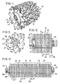
- FIG. 1 is a perspective view of a blade module comprising a portion of a knife roll assembly in accordance with the present invention;
- FIG. 2 is a side elevational view of the module of Fig. 1, showing the module carried on a shaft and with an end portion of the module broken away;
- FIG. 3 is a side elevational view of the knife roll assembly;
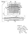
- FIG. 4 is a schematic view of a meat tenderizing machine with which the present invention may be used;
- FIG. 5 is a sectional view taken generally along line 5-5 of Fig. 2; and
- FIG. 6 is a plan view of an apparatus for forming a module for the assembly.
- Referring now to the drawings, and in particular Fig. 1, a
knife module 10 is shown in accordance with the present invention, having a plurality ofblades 12 secured in aligned fashion by asupport member 14. Each ofblades 12 define acentral opening 16 andsupport member 14 defines acentral opening 17, which together are aligned to define a shaft-receivingopening 18 extending the full length ofmodule 10. The module is thus adapted to be supported by a shaft for rotation in the direction indicated generally byarrow 20. - Referring now to Fig. 2,
module 10 is shown positioned on ashaft 22 extending the full length ofopening 18. As can also be seen, supportingmember 14 mounts theblades 12 so as to secure the blades with an equal spacing between each adjacent pair ofblades 12. In a preferred embodiment, the center-to-center spacing between an adjacent pair ofblades 12, indicated at 24, is 4.47 mm (0.176"). The preferred spacing between theend surface 26 ofknife support member 14 and theendmost blade 12, indicated generally at 28, is 2.23 mm (0.088"). These preferred dimensions are selected to correspond to typical blade spacings for tenderizers presently in commercial use. Of course, other dimensions may be selected as desired. - It is preferred that each
module 10 be provided with approximately ten to fifteen blades secured by thesupport member 14. However, this produces amodule 10 which is substantially shorter than a complete knife roll used within a tenderizer machine. Such a complete roll normally provides approximately forty blades, and it is entirely possible to form asingle module 10 having the necessary 40 blades. - As shown in Fig. 3, a
complete knife roll 30 is preferably produced by placing a plurality ofmodules 10 along asingle shaft 22.Shaft 22 is provided at one end with anappropriate abutment member 32, against which one of themodules 10 is placed.Successive modules 10 are positioned against each other with the end faces 26 of theirrespective support members 14 being disposed in contact with each other. Thus it is preferred that, regardless of the specific dimensions selected, the spacing between end face 26 ofsupport member 14 and theendmost blade 12 be half that of the spacing between adjacent pairs ofblades 12. As a result, the endmost blades onadjacent modules 10 have anindentical spacing 34 to that between adjacent blades on asingle module 10. - Alternatively, each module may be formed with the spacing between one
end face 26 ofsupport member 14 andendmost blade 12 be equal to the normal spacing between blades. In such a case, the opposite endmost blade itself serves as the opposite end face for the module. This arrangement is somewhat more restrictive, in that the modules must be properly oriented when placed onshaft 22, although this can be an advantage in some cases in ensuring proper rotational direction for theblades 12. - The
adjacent modules 10 are secured in position by a securing means placed at the end ofshaft 22. In Fig. 3, as an example, anut 36 fittable on a threadedportion 38 ofshaft 22 is shown. However, a wide variety of appropriate securing means may be used. In view of the prior art construction of knife rolls wherein individual blades and spacers are secured to a shaft by a securing means, a wide variety of possible securing means is known in the art. - Assembled knife rolls 30 may be installed within a tenderizer machine to operate to tenderize meat and other materials in a known manner. In general, referring to Fig. 4, a pair of knife rolls 30 are mounted such that the
blades 12 of therolls 30 intermesh.Shafts 22 supportingrolls 30 are counter-rotated, as indicated generally byarrows 40, and pieces of meat or other material are passed into the intermeshed portion ofblades 12 as indicated byarrow 42. Knife rolls 30 then engage the material to be tenderized, passing it through theblades 12 and out of the machine. In addition, acomb block 44 is provided for eachroll 30, including a plurality of slots (not shown) through which eachblade 12 must pass. These slots serve to remove meat or other material particles which may become lodged between theblades 12 as the tenderizer is operating. - One advantage of the present invention can be recognized from Figs. 3 and 4. It can be seen that all meat to be tenderized must pass over the central portion of the
roll 30, regardless of the width of the meat portions, while only relatively wide portions will traverse the outer portions of the roll. Thus, the central section of the roll will be subjected to the greatest wear, and inner blades will require replacement prior to outer blades. Due to the tediousness of roll assembly, it has been customary to replace the entire roll when the inner blades have become worn, rather than only those blades which require replacement. Using aroll 30 as shown in Fig. 3, however, one can replace only thecentral module 10 should the blades on such module become worn. Further, the outer modules can be turned around to move the outermost blades to a more central location, providing more even wear and more efficient blade usage. Also, modules can be interchanged alongshaft 22 to move, for example, an outer module to the central position. - Further detail regarding the construction of
module 10 can be seen by reference to Fig. 5. Eachblade 12, which is generally disc-shaped, is provided with a plurality of notches definingblade teeth 46 therebetween, each tooth having a cuttingedge 48 formed on its periphery.Blades 12 are shown having thirteenteeth 46 on each blade, but it should be recognized that a variety of different blade configurations can be and typically are used within tenderizing equipment. For example,blades 12 may be completely disc-shaped, having but a single cutting edge and no teeth. Alternatively,blades 12 may be star-shaped, having, for example, fiveteeth 48 on each blade. Such blade types, as well as many others, are well known within the art. - Further, it should be recognized that the term "blade" as used herein may also refer to disc-shaped members having other than a cutting surface, but used nonetheless within tenderizing equipment. For example, "blades" could be back-up roller segments arranged on a shaft for cooperation with blades for strip cutting, such as with food used in salads. Thus, each "blade" defines a working portion at its periphery, which may or may not be a true cutting edge.
- Each
blade 12 used within amodule 10 is stamped from stainless steel stock having relatively small thickness tolerance, e.g., ± 0.013 mm (0.0005"). As eachblade 12 is produced, thecentral opening 16 is also formed. In the preferred embodiment, opening 16 is hexagonal, selected to provide for driving engagement of thefinished module 10 with ahexangonal shaft 22. Of course, it will be recognized that other configurations for opening 16 (and shaft 22) are possible, such as triangular or square. In general, the selected shape should provide corners for engagement. - Along with
central opening 16, eachblade 12 is provided with a plurality ofholes 50 formed throughblade 12 betweenopening 16 and the outer periphery of the blade. Preferably, holes 50 are formed betweenopening 16 and the base of thenotches defining fingers 46.Holes 50 andsupport member 14 cooperate to provide a rigid structure formodule 10. -
Blade support member 14 is formed from a molded material, preferably a plastic material, and most preferably Celcon M90-04 (natural). The molded material ofsupport member 14 is disposed between each adjacent pair ofblades 12, and extends radially outwardly along eachblade 12 from opening 16 toward the periphery at whichteeth 46 and cuttingedges 48 are located. Further,member 14 extends over and beyond each of theholes 50, and the molded plastic material passes through theholes 50. This defines aunitary member 14 which securely positions and retains each of theblades 12 in their relative positions. - The molded material of
member 14 preferably does not extend into the area defined bycentral opening 16. Thus, whenmodule 10 is completed, the shaft-receiving opening 18 (see Fig. 1) is defined, and the shaft will contact the steel blades during driving of the module. - It should be recognized that it is not necessary for
holes 50 to be disposed on eachblade 12 in the exact number and positions shown in Fig. 5. What is important is that holes 50 be provided for allowing the plastic material ofmember 14 to secure the blades in place to definemodule 10. - It can be seen that a wide variety of alternatives exist for the
holes 50, including those shown in Fig. 5. For example,support member 14 could be extended radially outward to beyond the base ofblade teeth 46. In such a case, the molded material will then fill the bases of the notches defining the separation between each pair of teeth, producing the same effect as flow through holes 50. More material must be used for each module, but no holes need be formed intoblades 12. - It is an important feature of the invention that the inner portion of
blade 12 isadjacent shaft 22 whenmodule 10 is in position on the shaft, particularly at the corner regions of thenon-circular opening 16. Since the driving force ofshaft 22 is typically exerted most strongly at the corner regions, it is desirable to provide the additional strength of themetallic blades 12 alongopening 16. - It is also desirable that holes 50 be arranged on each
blade 12 symmetrically aroundopening 16. This will ensure that the strength of themodule 10 will be kept relatively uniform about the entire module. Six holes have been found to be adequate, arranged hexagonally to correspond to the shape of opening 16, and are therefore preferred. Other arrangements may also be suitable. - One method of making the
knife blade module 10 will be described with reference to Fig. 6. While this method represents the preferred method for making the module, it is merely exemplary. Other satisfactory methods may be devised by those skilled in the art. - A pair of co-operating mold halves are used in the method, with one
half 60 being shown in Fig. 6. A semi-cylindricalmain cavity 62 is defined, with a plurality of narrow, deepersemi-circular slots 64 arranged along the length ofcavity 62.Cavity 62 is formed to a depth equal to the desired radius forsupport member 14, while eachslot 64 is formed to a width equal to blade thickness and a depth equal to the radius ofblades 12.End openings 66 are provided to open intocavity 62, with eachopening 66 having a half-hexagonal configuration corresponding to one-half of the opening 16 (or shaft 22). - The apparatus further includes a
split runner block 68 formed in two halves or pieces. One-half ofblock 68 is shown in Fig. 6, with the understanding that the opposite half is identical. Asemi-cylindrical flow cavity 70 extends the length ofblock 68, and the outer configuration ofblock 68, when the two halves ofblock 68 are assembled, is identical to that ofshaft 22 with which the completedmodule 10 is to be used. A plurality of pin-point gates 72 are provided alongblock 68, to open fromcavity 70 to the exterior ofblock 68.Gates 72 are provided with spacings equal to the desired spacings forblades 12 on the completedmodule 10. - In producing the
module 10, the halves ofblock 68 are placed together, and the proper number ofblades 12 formodule 10 are placed ontoblock 68 by inserting the block through thehexagonal opening 16 in eachblade 12. Because opening 16 is hexagonal, while eachblade 12 is provided with thirteenteeth 46, it can be seen that a generally random distribution of blade orientations along themodule 10 can be produced simply by placing the blades onblock 68 without regard to their orientation. Such an arrangement is desirable in terms of performance of themodule 10 in operating upon meat or other material to be tenderized. (Of course, the blades can be arranged with teeth aligned if desirable.) - The
block 68 andblades 12 are next positioned within onehalf 60 of the mold. Eachblade 12 is fitted into one ofslots 64. Alternatively,blades 12 may be initially placed withinslots 64 withblock 68 inserted through the blades as indicated generally byarrow 74.Blades 12 fit snugly withinslots 64, and theopposite half 60 of the mold is positioned to close the mold. - The mold is next heated, one end of
cavity 70 inblock 68 is closed, and a molten plastic material is introduced under pressure into the opposite end ofcavity 70. Because of the relatively small size ofgates 72, the entire interior ofcavity 70 will tend to fill with the plastic material, thereby equalizing the pressure within opening 70 so that material emerges through eachgate 72 in generally uniform fashion. Becauseblock 68 is positioned within the mold so that eachgate 72 opens between an adjacent pair of blades, the plastic material flows into each gap between blades as it fills the mold. Since the material is under pressure, it also flows into theopenings 50 defined through each blade to connect the portions of material and form theunitary support member 14. - The mold is next cooled, whereupon the plastic material solidifies.
Runner block 68 is pressed out of the mold throughopenings 66. Because of the relatively small size ofgates 72, the plastic sprues formed through these gates are easily broken asblock 68 passes out of the mold. The mold is then opened and thefinished module 10 is removed. - It should be recognized that one advantage of the formation technique described above is that the broken connection points from the plastic sprues are all located along a portion of
member 14 which will be shielded from the food material byshaft 22. This is important, in that such connection points frequently result in rough edges which could tend to collect food particles through use of themodule 10, increasing the difficulty of keeping the apparatus thoroughly clean.
Claims (13)
- An integral circular knife module for a meat tenderizer or the like, for mounting on a rotary shaft (22) for driving the module to perform a gang-cutting action on material passing between the module and a back-up member, including
a plurality of disc-shaped, uniformly spaced knife blades (12) on a common axis, each of said blades having working portions at its periphery and defining a central shaft-receiving blade opening (16);
a blade support (14) including a unitary molded member for providing the axial spacing between adjacent ones of said blades and for gripping said blades, said molded member further defining a central shaft-receiving molded opening (17) and extending radially outwards from said central molded opening and terminating not farther than said working portions,
characterised in that the shaft (22) has a non-circular cross section, said central molded opening (17) and each of said central blade openings (16) being of an area substantially the same as said shaft cross section of the same non-circular shape, and coincident along a single axis, and in that the molded member comprises a plurality of spacer portions alternating with knife blades (12) along the shaft and integrally connected to one another through apertures (50) in the knife blades spaced radially from the central opening (17). - A knife module as defined in claim 1, wherein said apertures include at least one hole (50) defined through each of said blades (12), said molded member (14) extending radially outward beyond said holes and said molded member further having material passing through said holes of each of said blades to provide said unitary molded member.
- A knife module as defined in claim 2, wherein, each of said blades (12) defines a plurality of said holes (50).
- A knife module as defined in claim 3, wherein said holes (50) are disposed symmetrically about each of said blades (12).
- A knife module as defined in claim 4, wherein each of said blades (12) defines six of said holes (50) arranged in a hexagonal pattern around said central blade opening (16).
- A knife module as defined in claim 1, wherein:
each of said blades (12) defines a plurality of notches extending inwardly from the blade periphery to define a plurality of blade teeth (46), each of said notches having a base at its innermost portion. - A knife module as defined in claim 6 wherein said notches define said apertures and wherein said molded member has material passing through said bases of the notches to provide said unitary molded member.
- A knife module as defined in claim 6, wherein the molded member (14) extends radially with respect to the blades (12) to terminate short of any of the bases of said notches.
- A knife module as defined in any preceding claim, wherein the shaft-receiving openings (16,17) are hexagonal and the shaft is of hexagonal cross-section.
- A knife module as defined in any preceding claim, wherein said molded member (14) is formed from a thermoplastic material.
- A knife module as defined in any preceding claim, wherein said predetermined spaced relationship for said blades (12) includes a uniform spacing (24) between each adjacent pair of said blades.
- A knife module as defined in claim 11, wherein:
said blades (12) are further disposed to define a pair of end blades;
said blade support member extends beyond each of said end blades and defines a pair of planar end surfaces (26 parallel to said blades; and
each of said end surfaces is disposed from a corresponding one of said end blades by one-half of said uniform spacing separating adjacent pairs of said blades. - A knife module as defined in claim 11, wherein:
said blades (12) are further disposed to define a first and second end blade;
said blade support member extends beyond said first end blade and defines a first planar end surface parallel to said blades;
said first end surface is disposed from said first end blades by said uniform spacing separating adjacent pairs of said blades; and
a second planar end surface is defined by said second end blade.
Applications Claiming Priority (2)
| Application Number | Priority Date | Filing Date | Title |
|---|---|---|---|
| US06/833,694 US4660252A (en) | 1986-02-27 | 1986-02-27 | Knife roll assembly for a meat tenderizer |
| US833694 | 1986-02-27 |
Publications (3)
| Publication Number | Publication Date |
|---|---|
| EP0234829A2 EP0234829A2 (en) | 1987-09-02 |
| EP0234829A3 EP0234829A3 (en) | 1988-06-15 |
| EP0234829B1 true EP0234829B1 (en) | 1991-10-02 |
Family
ID=25265047
Family Applications (1)
| Application Number | Title | Priority Date | Filing Date |
|---|---|---|---|
| EP87301306A Expired EP0234829B1 (en) | 1986-02-27 | 1987-02-16 | Knife roll assembly for a meat tenderizer |
Country Status (7)
| Country | Link |
|---|---|
| US (1) | US4660252A (en) |
| EP (1) | EP0234829B1 (en) |
| JP (1) | JP2568189B2 (en) |
| AU (1) | AU586320B2 (en) |
| CA (1) | CA1281973C (en) |
| DE (1) | DE3773408D1 (en) |
| MX (1) | MX160385A (en) |
Families Citing this family (12)
| Publication number | Priority date | Publication date | Assignee | Title |
|---|---|---|---|---|
| US5269415A (en) * | 1992-07-21 | 1993-12-14 | Eastman Kodak Company | Rack for supporting rolls of web material plus apparatus and method for assembling such a rack |
| ATE237944T1 (en) * | 1999-10-08 | 2003-05-15 | Franz Kindermann | DEVICE FOR PROCESSING MEAT |
| USD481268S1 (en) | 2003-03-14 | 2003-10-28 | Sean F. Hibbert | Meat tenderizer with spiked roller and marinade-dispensing handle |
| AU2003282119A1 (en) * | 2003-11-24 | 2005-06-08 | Metalquimia, Sa | Tenderising machine |
| RU2271668C2 (en) * | 2004-06-01 | 2006-03-20 | Алексей Хусеинович Халваши | Tenderer |
| JP5464925B2 (en) * | 2009-06-26 | 2014-04-09 | 株式会社寿香 | Meat processing module for meat processing machine and meat processing machine using the same |
| US20110009041A1 (en) * | 2009-07-07 | 2011-01-13 | Ross Industries, Inc. | Food conditioner |
| US20110207389A1 (en) * | 2010-02-22 | 2011-08-25 | Leonard Deni | Meat tenderizer |
| KR200469735Y1 (en) * | 2012-05-16 | 2013-11-20 | 강신영 | Apparatus of tenderizing meat |
| WO2014181050A1 (en) * | 2013-04-12 | 2014-11-13 | Carollo Marc | Appliance and meat product |
| US10912308B2 (en) * | 2017-02-02 | 2021-02-09 | Ross Industries, Inc. | Cross cut tenderizer |
| JP7011495B2 (en) * | 2018-03-08 | 2022-01-26 | 伊藤ハム株式会社 | Dried meat products and their manufacturing methods |
Family Cites Families (10)
| Publication number | Priority date | Publication date | Assignee | Title |
|---|---|---|---|---|
| GB600527A (en) * | 1945-10-27 | 1948-04-12 | Berkel & Parnall Mach Mfg Co | Improvements relating to meat tendering machines |
| DE843508C (en) * | 1946-05-11 | 1952-07-10 | Toledo Scale Co | Machine for making meat |
| US2605497A (en) * | 1949-01-28 | 1952-08-05 | Cube Steak Machine Co | Meat treating machine |
| GB745198A (en) * | 1951-10-25 | 1956-02-22 | Robert Oscar Deckert | Food processing machine |
| US2886846A (en) * | 1957-03-28 | 1959-05-19 | Us Slicing Machine Co Inc | Meat tenderizer knife roll assembly |
| US3222713A (en) * | 1964-08-10 | 1965-12-14 | Stein Sam Ass | Meat scoring machine |
| CH481582A (en) * | 1967-07-21 | 1969-11-30 | Mutschlechner Heinrich | Kitchen hand tool for making meat cuts tender |
| US3523992A (en) * | 1968-01-02 | 1970-08-11 | Honeywell Inc | Fabrication of support-module |
| US3867502A (en) * | 1970-01-05 | 1975-02-18 | Carl A Moody | Making and employing hair teasing combs |
| US4200958A (en) * | 1977-09-20 | 1980-05-06 | Jurida Vladslav J | Kitchen utensil |
-
1986
- 1986-02-27 US US06/833,694 patent/US4660252A/en not_active Expired - Lifetime
-
1987
- 1987-02-12 CA CA000529616A patent/CA1281973C/en not_active Expired - Lifetime
- 1987-02-16 AU AU68840/87A patent/AU586320B2/en not_active Ceased
- 1987-02-16 DE DE8787301306T patent/DE3773408D1/en not_active Expired - Fee Related
- 1987-02-16 EP EP87301306A patent/EP0234829B1/en not_active Expired
- 1987-02-17 MX MX5246A patent/MX160385A/en unknown
- 1987-02-27 JP JP62045054A patent/JP2568189B2/en not_active Expired - Lifetime
Also Published As
| Publication number | Publication date |
|---|---|
| JP2568189B2 (en) | 1996-12-25 |
| AU6884087A (en) | 1987-09-03 |
| MX160385A (en) | 1990-02-14 |
| EP0234829A3 (en) | 1988-06-15 |
| DE3773408D1 (en) | 1991-11-07 |
| AU586320B2 (en) | 1989-07-06 |
| CA1281973C (en) | 1991-03-26 |
| JPS62241696A (en) | 1987-10-22 |
| EP0234829A2 (en) | 1987-09-02 |
| US4660252A (en) | 1987-04-28 |
Similar Documents
| Publication | Publication Date | Title |
|---|---|---|
| US4660252A (en) | Knife roll assembly for a meat tenderizer | |
| US3880030A (en) | Rotary cutter assembly | |
| DE60114771T2 (en) | PROCESS AND DEVICE FOR CRUSHING BLOCK MATERIAL | |
| US20210094042A1 (en) | Shredder blade assembly | |
| HK1049428A1 (en) | Dough forming apparatus and methods | |
| CA2051919A1 (en) | Food slicing with multiple cutting surface blade | |
| EP4291372A1 (en) | Impellers for cutting machines and cutting machines equipped therewith | |
| US20240075646A1 (en) | Impellers for Cutting Machines and Cutting Machines Equipped with Impellers | |
| DE2707842A1 (en) | SCRAPER AND RASP DEVICE FOR REMOVING TIRE TREATS | |
| US4108033A (en) | Rotary cutting device for forming strips of shaped article preforms | |
| HK155096A (en) | Apparatus for cutting wafer shell valves | |
| JP3623187B2 (en) | Shearing crusher | |
| EP3381563B1 (en) | Chipper rotor | |
| DE9214288U1 (en) | Device for grating or shredding food | |
| EP2549892B1 (en) | Blade box for disintegrating device for organic matter | |
| EP1389045A1 (en) | Device for the production of food kebabs, in particular of shish kebabs and similar | |
| US12514256B1 (en) | Multi-directional cut tenderizing assembly | |
| CN222200714U (en) | A tangerine peel shredding machine | |
| AU2020473992B2 (en) | Impellers for cutting machines and cutting machines equipped therewith | |
| CA2573830A1 (en) | Bagel dough dividing apparatus | |
| KR200328514Y1 (en) | Gap-adjusting apparatus for a knife unit strip cutter machine | |
| DE2719891A1 (en) | Frozen meat cube cutting machine - with cutter discs on drum having alternate protruding and re=entrant teeth | |
| DE202025101938U1 (en) | Cutting device, in particular for micro-shredders, continuous micro-shredders, cutters and the like. | |
| KR960010137Y1 (en) | Sashimi cutting machine | |
| WO2017007449A1 (en) | Shredder blade assembly |
Legal Events
| Date | Code | Title | Description |
|---|---|---|---|
| PUAI | Public reference made under article 153(3) epc to a published international application that has entered the european phase |
Free format text: ORIGINAL CODE: 0009012 |
|
| AK | Designated contracting states |
Kind code of ref document: A2 Designated state(s): DE FR GB NL |
|
| PUAL | Search report despatched |
Free format text: ORIGINAL CODE: 0009013 |
|
| AK | Designated contracting states |
Kind code of ref document: A3 Designated state(s): DE FR GB NL |
|
| 17P | Request for examination filed |
Effective date: 19880919 |
|
| 17Q | First examination report despatched |
Effective date: 19900122 |
|
| RAP1 | Party data changed (applicant data changed or rights of an application transferred) |
Owner name: PREMARK FEG CORPORATION |
|
| GRAA | (expected) grant |
Free format text: ORIGINAL CODE: 0009210 |
|
| AK | Designated contracting states |
Kind code of ref document: B1 Designated state(s): DE FR GB NL |
|
| PG25 | Lapsed in a contracting state [announced via postgrant information from national office to epo] |
Ref country code: NL Effective date: 19911002 |
|
| REF | Corresponds to: |
Ref document number: 3773408 Country of ref document: DE Date of ref document: 19911107 |
|
| ET | Fr: translation filed | ||
| PGFP | Annual fee paid to national office [announced via postgrant information from national office to epo] |
Ref country code: NL Payment date: 19920229 Year of fee payment: 6 |
|
| NLV1 | Nl: lapsed or annulled due to failure to fulfill the requirements of art. 29p and 29m of the patents act | ||
| PLBE | No opposition filed within time limit |
Free format text: ORIGINAL CODE: 0009261 |
|
| STAA | Information on the status of an ep patent application or granted ep patent |
Free format text: STATUS: NO OPPOSITION FILED WITHIN TIME LIMIT |
|
| 26N | No opposition filed | ||
| REG | Reference to a national code |
Ref country code: GB Ref legal event code: 732E |
|
| REG | Reference to a national code |
Ref country code: FR Ref legal event code: TP |
|
| PGFP | Annual fee paid to national office [announced via postgrant information from national office to epo] |
Ref country code: FR Payment date: 20010131 Year of fee payment: 15 |
|
| PGFP | Annual fee paid to national office [announced via postgrant information from national office to epo] |
Ref country code: DE Payment date: 20010201 Year of fee payment: 15 |
|
| PGFP | Annual fee paid to national office [announced via postgrant information from national office to epo] |
Ref country code: GB Payment date: 20010202 Year of fee payment: 15 |
|
| REG | Reference to a national code |
Ref country code: GB Ref legal event code: IF02 |
|
| PG25 | Lapsed in a contracting state [announced via postgrant information from national office to epo] |
Ref country code: GB Free format text: LAPSE BECAUSE OF NON-PAYMENT OF DUE FEES Effective date: 20020216 |
|
| PG25 | Lapsed in a contracting state [announced via postgrant information from national office to epo] |
Ref country code: DE Free format text: LAPSE BECAUSE OF NON-PAYMENT OF DUE FEES Effective date: 20020903 |
|
| GBPC | Gb: european patent ceased through non-payment of renewal fee |
Effective date: 20020216 |
|
| PG25 | Lapsed in a contracting state [announced via postgrant information from national office to epo] |
Ref country code: FR Free format text: LAPSE BECAUSE OF NON-PAYMENT OF DUE FEES Effective date: 20021031 |
|
| REG | Reference to a national code |
Ref country code: FR Ref legal event code: ST |