EP0233434B1 - Apparatus for the distribution of thermoplastic material for the manufacture of multi-layered sheets - Google Patents
Apparatus for the distribution of thermoplastic material for the manufacture of multi-layered sheets Download PDFInfo
- Publication number
- EP0233434B1 EP0233434B1 EP86402972A EP86402972A EP0233434B1 EP 0233434 B1 EP0233434 B1 EP 0233434B1 EP 86402972 A EP86402972 A EP 86402972A EP 86402972 A EP86402972 A EP 86402972A EP 0233434 B1 EP0233434 B1 EP 0233434B1
- Authority
- EP
- European Patent Office
- Prior art keywords
- central channel
- channel
- die
- regulating means
- additional material
- Prior art date
- Legal status (The legal status is an assumption and is not a legal conclusion. Google has not performed a legal analysis and makes no representation as to the accuracy of the status listed.)
- Expired
Links
Images
Classifications
-
- B—PERFORMING OPERATIONS; TRANSPORTING
- B29—WORKING OF PLASTICS; WORKING OF SUBSTANCES IN A PLASTIC STATE IN GENERAL
- B29C—SHAPING OR JOINING OF PLASTICS; SHAPING OF MATERIAL IN A PLASTIC STATE, NOT OTHERWISE PROVIDED FOR; AFTER-TREATMENT OF THE SHAPED PRODUCTS, e.g. REPAIRING
- B29C48/00—Extrusion moulding, i.e. expressing the moulding material through a die or nozzle which imparts the desired form; Apparatus therefor
- B29C48/03—Extrusion moulding, i.e. expressing the moulding material through a die or nozzle which imparts the desired form; Apparatus therefor characterised by the shape of the extruded material at extrusion
- B29C48/07—Flat, e.g. panels
- B29C48/08—Flat, e.g. panels flexible, e.g. films
-
- B—PERFORMING OPERATIONS; TRANSPORTING
- B29—WORKING OF PLASTICS; WORKING OF SUBSTANCES IN A PLASTIC STATE IN GENERAL
- B29C—SHAPING OR JOINING OF PLASTICS; SHAPING OF MATERIAL IN A PLASTIC STATE, NOT OTHERWISE PROVIDED FOR; AFTER-TREATMENT OF THE SHAPED PRODUCTS, e.g. REPAIRING
- B29C48/00—Extrusion moulding, i.e. expressing the moulding material through a die or nozzle which imparts the desired form; Apparatus therefor
- B29C48/16—Articles comprising two or more components, e.g. co-extruded layers
- B29C48/18—Articles comprising two or more components, e.g. co-extruded layers the components being layers
- B29C48/21—Articles comprising two or more components, e.g. co-extruded layers the components being layers the layers being joined at their surfaces
-
- B—PERFORMING OPERATIONS; TRANSPORTING
- B29—WORKING OF PLASTICS; WORKING OF SUBSTANCES IN A PLASTIC STATE IN GENERAL
- B29C—SHAPING OR JOINING OF PLASTICS; SHAPING OF MATERIAL IN A PLASTIC STATE, NOT OTHERWISE PROVIDED FOR; AFTER-TREATMENT OF THE SHAPED PRODUCTS, e.g. REPAIRING
- B29C48/00—Extrusion moulding, i.e. expressing the moulding material through a die or nozzle which imparts the desired form; Apparatus therefor
- B29C48/25—Component parts, details or accessories; Auxiliary operations
- B29C48/30—Extrusion nozzles or dies
- B29C48/305—Extrusion nozzles or dies having a wide opening, e.g. for forming sheets
- B29C48/307—Extrusion nozzles or dies having a wide opening, e.g. for forming sheets specially adapted for bringing together components, e.g. melts within the die
-
- B—PERFORMING OPERATIONS; TRANSPORTING
- B29—WORKING OF PLASTICS; WORKING OF SUBSTANCES IN A PLASTIC STATE IN GENERAL
- B29C—SHAPING OR JOINING OF PLASTICS; SHAPING OF MATERIAL IN A PLASTIC STATE, NOT OTHERWISE PROVIDED FOR; AFTER-TREATMENT OF THE SHAPED PRODUCTS, e.g. REPAIRING
- B29C48/00—Extrusion moulding, i.e. expressing the moulding material through a die or nozzle which imparts the desired form; Apparatus therefor
- B29C48/25—Component parts, details or accessories; Auxiliary operations
- B29C48/36—Means for plasticising or homogenising the moulding material or forcing it through the nozzle or die
- B29C48/49—Means for plasticising or homogenising the moulding material or forcing it through the nozzle or die using two or more extruders to feed one die or nozzle
-
- B—PERFORMING OPERATIONS; TRANSPORTING
- B29—WORKING OF PLASTICS; WORKING OF SUBSTANCES IN A PLASTIC STATE IN GENERAL
- B29C—SHAPING OR JOINING OF PLASTICS; SHAPING OF MATERIAL IN A PLASTIC STATE, NOT OTHERWISE PROVIDED FOR; AFTER-TREATMENT OF THE SHAPED PRODUCTS, e.g. REPAIRING
- B29C48/00—Extrusion moulding, i.e. expressing the moulding material through a die or nozzle which imparts the desired form; Apparatus therefor
- B29C48/03—Extrusion moulding, i.e. expressing the moulding material through a die or nozzle which imparts the desired form; Apparatus therefor characterised by the shape of the extruded material at extrusion
- B29C48/12—Articles with an irregular circumference when viewed in cross-section, e.g. window profiles
-
- Y—GENERAL TAGGING OF NEW TECHNOLOGICAL DEVELOPMENTS; GENERAL TAGGING OF CROSS-SECTIONAL TECHNOLOGIES SPANNING OVER SEVERAL SECTIONS OF THE IPC; TECHNICAL SUBJECTS COVERED BY FORMER USPC CROSS-REFERENCE ART COLLECTIONS [XRACs] AND DIGESTS
- Y10—TECHNICAL SUBJECTS COVERED BY FORMER USPC
- Y10T—TECHNICAL SUBJECTS COVERED BY FORMER US CLASSIFICATION
- Y10T137/00—Fluid handling
- Y10T137/8593—Systems
- Y10T137/877—With flow control means for branched passages
- Y10T137/87885—Sectional block structure
Landscapes
- Engineering & Computer Science (AREA)
- Mechanical Engineering (AREA)
- Manufacturing & Machinery (AREA)
- Extrusion Moulding Of Plastics Or The Like (AREA)
- Laminated Bodies (AREA)
- Processes Of Treating Macromolecular Substances (AREA)
Abstract
Description
La présente invention se rapporte à la fabrication de feuilles comprenant des couches superposées de matière thermoplastique ou autre, par extrusion simultanée de divers matériaux, puis par réunion de ceux-ci avant leur introduction dans une filière.The present invention relates to the manufacture of sheets comprising superimposed layers of thermoplastic or other material, by simultaneous extrusion of various materials, then by joining together before their introduction into a die.
Pour réunir les matériaux en évitant leur mélange, on les introduit en des écoulements coaxiaux, ou tout au moins parallèles, dans le canal d'entrée d'une filière. L'utilisation d'écoulements cylindriques coaxiaux permet d'obtenir une feuille comprenant une couche interne et au moins une couche en enveloppe autour de cette couche interne. La feuille est toujours constituée par un matériau sandwich dans lequel les couches sont disposées de façon symétrique ou non par rapport à la couche interne.To bring the materials together while avoiding their mixing, they are introduced in coaxial, or at least parallel, flows into the inlet channel of a die. The use of coaxial cylindrical flows makes it possible to obtain a sheet comprising an internal layer and at least one envelope layer around this internal layer. The sheet is always made of a sandwich material in which the layers are arranged symmetrically or not with respect to the internal layer.
Pour remédier à cela, on a déjà envisagé de disposer sur le trajet des écoulements des cloisons radiales de façon à diviser les écoulements extérieurs et à permettre d'injecter des matières différentes de chaque côté de la couche interne. Dans d'autres cas, on utilise des conduits parallèles séparés par des cloisons, dans lequels on introduit les différentes matières qui ne viennent en contact l'une de l'autre qu'au bout d'un certain trajet parallèle de façon à éviter tout risque d'écoulement turbulent et de mélange.To remedy this, it has already been envisaged to have on the path of the flows of the radial partitions so as to divide the external flows and to make it possible to inject different materials on each side of the internal layer. In other cases, parallel conduits are used, separated by partitions, in which the various materials are introduced which do not come into contact with each other until after a certain parallel path so as to avoid any risk of turbulent flow and mixing.
On connaît également dans le FR-A 2 437 289, au nom de la Demanderesse, un dispositif d'alimentation d'une filière de fabrication de feuilles en matière thermoplastique multicouches qui est raccordé à au moins deux extrudeuses de matière thermoplastique et dans lequel plusieurs écoulements de matière sont réunis dans un canal central raccordé à l'entrée de la filière. Ce dispositif comporte un ensemble d'éléments juxtaposés définissant le canal central, raccordé à l'entrée de la filière un bloc d'entrée disposé à une extrémité dudit ensemble juxtaposés et dans lequel sont pratiqués des passages raccordés respectivement auxdites arrivées, chaque élément comportant au moins un canal radial débouchant dans le canal central et communiquant avec l'un des passages du bloc d'entrée, éventuellement par l'intermédiaire de passages pratiqués dans les éléments situés en aval par rapport à l'écoulement de la matière.Also known in FR-A 2 437 289, in the name of the Applicant, is a device for feeding a die for manufacturing sheets of multilayer thermoplastic material which is connected to at least two extruders of thermoplastic material and in which several material flows are combined in a central channel connected to the inlet of the die. This device comprises a set of juxtaposed elements defining the central channel, connected to the inlet of the die an inlet block disposed at one end of said juxtaposed set and in which passages are made connected respectively to said inlets, each element comprising at at least one radial channel opening into the central channel and communicating with one of the passages of the inlet block, possibly via passages made in the elements located downstream with respect to the flow of the material.
Grâce à cette disposition, chaque élément de l'ensemble d'éléments juxtaposés est affecté à une couche ou à des couches bien déterminées du boudin de matière multicouches introduit dans la filière.Thanks to this arrangement, each element of the set of juxtaposed elements is assigned to a well-defined layer or layers of the strand of multilayer material introduced into the die.
Cette disposition implique une arrivée successive de chacun des flux sur ce boudin central de matière qui sera lui-même finalement introduit dans la filière.This arrangement implies a successive arrival of each of the flows on this central rod of material which will itself be finally introduced into the die.
La régularité et l'homogénéité du boudin fourni à la filière dépendent notamment de celles des extrudeuses, des viscosités relatives des matières plastiques utilisées et également des dimensions des divers canaux et passages d'alimentation. Par ailleurs, les profils des divers- passages et canaux déterminent dans une mesure importante la forme de la section transversale de la veine de matière apportée au boudin principal dans le canal central.The regularity and the homogeneity of the rod supplied to the die depend in particular on those of the extruders, on the relative viscosities of the plastics used and also on the dimensions of the various feed channels and passages. Furthermore, the profiles of the various passages and channels determine to a significant extent the shape of the cross section of the stream of material supplied to the main rod in the central channel.
Par conséquent, la forme de la section transversale des différentes veines du boudin de sortie doivent être choisies au préalable par le dimensionnement approprié des passages et des canaux.Therefore, the shape of the cross section of the different veins of the outlet tube must be chosen beforehand by the appropriate dimensioning of the passages and channels.
D'autre part, pour adapter un élément déterminé à un matériau déterminé fourni par les extrudeuses, il faut changer la forme des passages radiaux de l'élément correspondant. Par conséquent, ces opérations d'adaptation doivent être effectuées avant le fonctionnement de l'installation, en procédant au démontage du dispositif.On the other hand, to adapt a specific element to a specific material supplied by the extruders, it is necessary to change the shape of the radial passages of the corresponding element. Consequently, these adaptation operations must be carried out before the installation operates, by dismantling the device.
Pendant le fonctionnement, la répartition du matériau de chaque couche sur la surface du matériau adjacent peut être corrigée par une modification de la viscosité relative des matériaux par réglage de température des matières introduites.During operation, the distribution of the material of each layer on the surface of the adjacent material can be corrected by modifying the relative viscosity of the materials by adjusting the temperature of the materials introduced.
Or, la plage de réglage de la température est étroite, car pour une température trop basse, on risque d'obstruer les passages radiaux des anneaux, et pour une température trop élevée, on risque de brûler la matière. De plus, le temps de réaction à la suite de chaque changement de température est relativement long, si bien que ce seul moyen de réglage en fonctionnement ne permet pas d'obtenir une précison satisfaisante du profil des différentes couches de façon rapide et aisée.However, the temperature adjustment range is narrow, because for a too low temperature, there is a risk of obstructing the radial passages of the rings, and for a too high temperature, there is a risk of burning the material. In addition, the reaction time following each change in temperature is relatively long, so that this only means of adjustment in operation does not allow satisfactory accuracy of the profile of the different layers to be obtained quickly and easily.
L'invention a pour but de fournir un dispositif de répartition de la matière thermoplastique introduite pour l'alimentation d'une filière de formation de feuilles multicouches, dont la construction est très simple et qui permet, moyennant une opération facile à exécuter, de régler et d'ajuster pendant le fonctionnement le profil des différentes veines de matière dans le répartiteur de façon à obtenir la répartition adéquate en sortie de la filière, tout en évitant les perturbations pendant les réglages.The object of the invention is to provide a device for distributing the thermoplastic material introduced for the supply of a multilayer sheet forming die, the construction of which is very simple and which makes it possible, by means of an easy operation to perform, to adjust and adjust during operation the profile of the different veins of material in the distributor so as to obtain the appropriate distribution at the outlet of the die, while avoiding disturbances during the adjustments.
L'invention a donc pour objet un dispositif de répartition de la matière thermoplastique ou analogue introduite dans un ensemble d'alimentation d'une filière de fabrication de feuilles multicouches qui est raccordé à au moins deux arrivées de matière thermoplastique et qui comporte un ensemble d'éléments juxtaposés de manière à définir un canal central raccordé à l'entrée de la filière, un bloc d'entrée disposé à une extrémité dudit ensemble d'éléments juxtaposés et dans lequel sont pratiqués des passages raccordés respectivement auxdites arrivées, chaque élément comportant au moins un canal radial débouchant dans ledit canal central et communiquant avec l'un des passages du bloc d'entrée, ce dispositif de répartition étant caractérisé en ce qu'il comporte au niveau de la jonction du canal radial d'arrivée de la matière supplémentaire introduite sur la matière réceptrice préalablement introduite dans le canal central, un organe de réglage progressif disposé dans chaque élément correspondant de l'ensemble d'alimentation, de façon à modifier instantanément dans le plan de superposition des matières thermoplastiques la forme de la section transversale de la veine de matière supplémentaire correspondante dans le canal central pour obtenir la répartition souhaitée de cette matière dans la feuille à la sortie de la filière.The invention therefore relates to a device for distributing the thermoplastic material or the like introduced into a supply assembly for a die for manufacturing multilayer sheets which is connected to at least two arrivals of thermoplastic material and which comprises a set of 'elements juxtaposed so as to define a central channel connected to the inlet of the die, an inlet block arranged at one end of said set of juxtaposed elements and in which are made passages connected respectively to said inlets, each element comprising at at least one radial channel opening into said central channel and communicating with one of the passages of the inlet block, this distribution device being characterized in that it comprises at the junction of the radial channel of arrival of the additional material introduced on the receiving material previously introduced into the central channel, a progressive adjustment member disposed in each corresponding element nd of the supply assembly, so as to instantly modify in the superposition plane of the thermoplastic materials the shape of the cross section of the corresponding stream of additional material in the central channel to obtain the desired distribution of this material in the sheet at the exit of the die.
D'autres développements avantageux du dispositif selon la présente invention font l'object des revendications dépendantes.Other advantageous developments of the device tif according to the present invention are the subject of dependent claims.
Selon un développement avantageux du dispositif selon l'invention, l'organe de réglage progressif comporte des moyens pour diriger la matière supplémentaire provenant du canal radial vers le canal central et des moyens pour régler la largeur de la veine de la matière introduite par rapport à la largeur dudit canal central, en fonction de la viscosité relative de la matière supplémentaire injectée, de la viscosité relative de la matière réceptrice et des températures d'utilisation de chacune des matières.According to an advantageous development of the device according to the invention, the progressive adjustment member comprises means for directing the additional material coming from the radial channel towards the central channel and means for adjusting the width of the vein of the material introduced with respect to the width of said central channel, as a function of the relative viscosity of the additional material injected, the relative viscosity of the receiving material and the temperatures of use of each of the materials.
D'autres particularités et avantages de l'invention ressortiront de la description qui va suivre, donnée à titre d'exemple non limitatif et en regard des dessins annexés, sur lesquels:
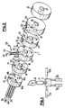
- - la figure 1 est une représentation schématique d'une installation de fabrication de feuilles multicouches en matière thermoplastique;
- - la figure 2 est une représentation schématique en perspective de l'ensemble d'alimentation muni du dispositif de répartition conforme à l'invention;
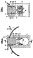
- - la figure 3 est une vue en coupe dans un plan perpendiculaire à l'axe du canal central du dispositif de répartition conforme à l'invention;
- - la figure 4 est une vue en coupe axiale selon la ligne IV-IV de la figure 3;
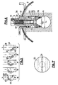
- - la figure 5 est une représentation schématique montrant les différentes positions du dispositif de répartition conforme à l'invention;
- - la figure 6 est une vue d'un autre mode de réalisation du dispositif suivant l'invention;
- - la figure 7 est une représentation d'un autre mode de réalisation du plot d'injection de la matière.
- - Figure 1 is a schematic representation of an installation for manufacturing multilayer sheets of thermoplastic material;
- - Figure 2 is a schematic perspective representation of the supply assembly provided with the distribution device according to the invention;
- - Figure 3 is a sectional view in a plane perpendicular to the axis of the central channel of the distribution device according to the invention;
- - Figure 4 is an axial sectional view along the line IV-IV of Figure 3;
- - Figure 5 is a schematic representation showing the different positions of the distribution device according to the invention;
- - Figure 6 is a view of another embodiment of the device according to the invention;
- - Figure 7 is a representation of another embodiment of the material injection pad.
Sur la figure 1, on a représenté le schéma d'une installation de fabrication de feuilles multicouches en matière thermoplastiques ou analogue, comportant un ensemble d'alimentation muni du dispositif de répartition de la matière introduit suivant l'invention. Cette installation comprend une filière A dont l'entrée B est connectée à un ensemble d'alimentation 1. Cet ensemble d'alimentation reçoit, soit directement, soit par l'intermédiaire d'un bloc collecteur C, plusieurs écoulements de matière thermoplastique de natures différentes. Dans l'exemple représenté, cet ensemble est raccordé à quatre extrudeuses D1 à D4.In Figure 1, there is shown the diagram of an installation for manufacturing multilayer sheets of thermoplastic material or the like, comprising a supply assembly provided with the material distribution device introduced according to the invention. This installation comprises a die A, the input B of which is connected to a supply assembly 1. This supply assembly receives, either directly or via a collecting block C, several flows of thermoplastic material of a kind different. In the example shown, this assembly is connected to four extruders D1 to D4.
Comme on peut le voir d'après la figure 2, l'ensemble d'alimentation 1 comporte des élémens juxtaposés, constitués notamment de quatre éléments 10 à 13, placés entre un bloc d'entrée 14 et un . bloc de sortie 15 tous deux coaxiaux aux éléments 10 à 13.As can be seen from Figure 2, the supply assembly 1 comprises juxtaposed elements, consisting in particular of four
L'ensemble de ces pièces sont réunies entre elles par exemple par des tiges filetées non représentées.All of these parts are joined together for example by threaded rods not shown.
Le bloc d'entrée 14 comporte quatre passages 14a à 14d qui, en amont, sont destinés à être raccordés aux extrudeuses respectives D1 à D4 (figure 1).The
Les éléments 10 à 13 comportent un orifice central dont l'alignement définit un canal central 16 de l'ensemble d'alimentation 1, canal qui débouche dans un passage central de sortie 17 pratiqué dans le bloc de sortie 15 et destiné à être raccordé à l'entrée B de la filière A.The
L'élément 10 comporte dans sa face tournée vers le bloc d'entrée 14, une rainure radiale 18 qui communique avec le passage 14c du bloc d'entrée 14 et qui débouche dans le canal central 16. Cet élément présente en outre trois passages axiaux 19, 20, 21 qui le traverse de part en part et qui sont décalés, dans cet exemple, de 90° par rapport à l'axe des éléments.The
L'élément 11 présente tout d'abord deux passages axiaux 22 et 23 communiquant respectivement avec les passages 19 et 21 de l'élément 10. Cet élément 11 comporte également un passage axial 24 aligné sur le passage 20 de l'élément 10 et débouchant, par l'intermédiaire d'un canal radial 25, dans un trou vertical 26 prévu à l'intérieur dudit élément 11. Ce trou vertical 26 traverse la partie supérieure de l'élément 11 et débouche dans le canal central 16. A l'intérieur de ce trou vertical est placé un organe 50 de réglage progressif de la répartition de la matière introduite dans le canal central 16 et provenant du canal radial 25.The element 11 firstly has two
Cet organe de réglage 50 sera décrit plus en détail ultérieurement en se reportant aux figures 3 et 4.This
L'élément 12 comporte à son tour, un premier passage axial 27 qui communique avec les passages axiaux 22 et 19 des éléments 11 et 10, respectivement. Cet élément 12 comporte un autre passage axial 28 aligné sur le passage 23 de l'élément 11 et débouchant, par l'intermédiaire d'un canal radial 29, dans un trou vertical 30 prévu à l'intérieur dudit élément 12. Ce trou vertical 30 traverse la partie supérieure de l'élément 12 et débouche dans le canal central 16. A l'intérieur de ce trou vertical est également placé un organe 50 de réglage progressif de la répartition de la matière introduite dans le canal central 16 et provenant du canal radial 29.The
L'élément 13 est pourvu d'un passage axial 31 qui communique avec les passages axiaux 27, 22 et 19 des éléments 12, 11 et 10, respectivement. Ce passage axial 31 débouche par l'intermédiaire d'un canal radial 32 dans un trou vertical 33 percé à l'intérieur de l'élément 13. A l'intérieur de ce trou vertical est également placé un organe 50 de réglage progressif de la répartition de la matière à introduire dans le canal central 16 et provenant du canal radial 32. Comme l'élément 13 est le dernier de l'ensemble d'alimentation 1, il ne comporte aucun autre passage de liaison. Chaque organe de réglage 50 agit au niveau de la jonction entre le canal radial (25, 29, 32) d'arrivée de la matière supplémentaire introduite dans le canal central 16.The
En se reportant maintenant aux figures 3 et 4, on va décrire plus en détail l'organe de réglage 50 placé par exemple dans l'élément 11, les autres organes de réglage 50 disposés dans les éléments 12 et 13 étant absolument identiques.Referring now to Figures 3 and 4, we will describe in more detail the adjusting
Sur ces figures 3 et 4, on voit l'élément 11 avec son canal central 16 dans lequel débouche le trou vertical 26 communiquant avec le canal radial 25 d'arrivée de la matière à introduire dans ledit canal central 16.In these FIGS. 3 and 4, the element 11 is seen with its
A l'intérieur de ce trou vertical 26 est positionné l'organe de réglage 50 qui comporte des moyens pour, d'une part diriger la matière provenant du canal radial 25 vers le canal central 16 et, d'autre part modifier la largeur de la veine de la matière introduite par rapport à la largeur dudit canal central 16.Inside this
A cet effet, l'organe de réglage 50 se compose d'un corps cylindrique 51 muni d'un plot d'injection 52 interchangeable et solidaire en rotation avec ledit corps à l'intérieur du trou 26.To this end, the adjusting
Le plot d'injection 52 est pourvu à sa partie supérieure d'un rebord 52a en forme de T (figure 4) qui est introduit dans une rainure correspondante 51 a formée à l'intérieur du corps cylindrique 51, permettant ainsi un changement rapide dudit plot lorsque l'ensemble est sorti du trou cylindrique 26.The
Le plot d'injection 52 comporte intérieurement un ajutage 53 se terminant à sa partie inférieure par une zone d'injection délimitée par un contour de forme allongée pour l'introduction et la répartition de la matière dans le canal central 16. Cette zone d'injection est par exemple constituée par une fente 54 de section rectangulaire.The
Le corps cylindrique 51 est pourvu d'une gorge annulaire 55 qui communique avec l'ajutage 53 du plot d'injection 52 par des petits orifices 56 et 57.The
Le corps cylindrique 51 et le plot d'injection 52 sont maintenus dans le trou vertical 26 par exemple par deux goupilles 58 et 59 et positionnés de telle manière que le canal radial 25 d'arrivée de la matière soit mis en communication avec le canal central 16 par la gorge annulaire 55, les petits orifices 56 et 57, et l'ajutage 53. Les goupilles 58 et 59 pénétrent dans des trous prévus à l'intérieur de l'anneau 11 et également dans une gorge circulaire 60 prévue dans le corps 51 ce qui assure le blocage vertical dudit corps tout en permettant sa rotation avec le plot d'injection 52.The
Par ailleurs, le corps cylindrique 51 comporte des moyens de positionnement en rotation et de repérage de l'axe longitudinal de la fente 54 du plot d'injection 52 par rapport à l'axe longitudinal du canal central 16.Furthermore, the
Pour cela, la tête du corps cylindrique 51 est formée par une molette 61 comportant, sur un quart de sa périphérie, des crans 62 (figure 5) pour l'introduction d'une petite goupille 63 qui assure ainsi le blocage de l'ensemble corps cylindrique 51 et plot d'injection 52 et le repérage de la position de la fente 54.For this, the head of the
Comme on le voit sur la figure 5, la molette 61 comporte en face de chaque cran 62 des repères de 1 à 5 qui correspondent, par exemple, pour le repère 1 à une position de la fente 54 perpendiculaire au sens d'écoulement de la matière dans le canal central 16, pour le repère 5 une position parallèle au sens d'écoulement de la matière, et pour les repères 2 à 4 à des positions intermédiaires.As can be seen in FIG. 5, the
La rotation de la molette 61 est limitée, sur 90° correspondant aux crans 62, par une butée 64 (figure 4).The rotation of the
Selon un autre mode de réalisation, le positionnement angulaire de la fente 54 peut être effectué en des positions quelconques dans la plage de 90° nécessaire, à l'aide d'un dispositif de variation continue par exemple du type roue-vis sans fin avec repérage sur un vernier de précision suffisante.According to another embodiment, the angular positioning of the
A la sortie de l'ensemble d'alimentation 1, les différentes couches de matière plastique introduites se déplacent avec des vitesses identiques et le boudin composé par ces couches peut ainsi entrer dans la filière A. Les épaisseurs de chaque couche se trouvent dans le produit final en fonction du choix des débits des extrudeuses respectives D1 à D4. La régularité et l'homogénéité du boudin fourni à la filière dépendent notamment de celles des extrudeuses, des viscosités relatives des matières plastiques utilisées et également des divers canaux et passages de l'ensemble d'alimentation.At the outlet of the supply assembly 1, the different layers of plastic material introduced move with identical speeds and the tube formed by these layers can thus enter the die A. The thicknesses of each layer are found in the product final according to the choice of the flow rates of the respective extruders D1 to D4. The regularity and the homogeneity of the rod supplied to the die depend in particular on those of the extruders, on the relative viscosities of the plastics used and also on the various channels and passages of the supply assembly.
Par conséquent, en fonction de la viscosité de la matière introduite, de la viscosité de la matière réceptrice, et de la température d'utilisation de chacune des maitères, on détermine et on règle par l'intermédiaire des organes 50 placés dans chacun des éléments 11, 12 et 13, la position de la fente 54 desdits organes 50 pour l'introduction de la matière provenant respectivement des extrudeuses D2 à D4 sur la matière réceptrice préalablement introduite dans l'élément 10 et provenant de l'extrudeuse D1, de façon à former des couches selon la répartition souhaitée.Consequently, as a function of the viscosity of the material introduced, the viscosity of the receiving material, and the temperature of use of each of the materials, it is determined and adjusted by means of the
De plus, si au cours des différents contrôles effectués à la sortie de la filière A sur la feuille finale, on s'aperçoit que l'une des couches ne correspond pas à la répartition désirée, on peut agir immédiatement sur l'organe de réglage 50 correspondant à ladite couche, pour corriger cette imperfection.In addition, if during the various checks carried out at the exit of die A on the final sheet, we notice that one of the layers does not correspond to the desired distribution, we can act immediately on the adjusting
En effet, dans le cas où la couche défectueuse présente un profil trop convexe, c'est-à-dire moins épais sur ses bords latéraux, il suffit de modifier la position de la fente 54 en augmentant le rapport I/L, où 1 représente la largeur de la veine de matière introduite et L la largeur du canal central (figure 5), correspondant à la veine de matière réceptrice préalablement introduite.Indeed, in the case where the defective layer has a too convex profile, that is to say less thick on its lateral edges, it suffices to modify the position of the
Par conséquent, on tourne la molette 61 pour placer la goupille 63 dans le cran correspondant par exemple au repère 1 ou 2, et ainsi positionner la fente 54 comme représenté sur les figures 5a ou 5b, ce qui permet d'augmenter la largeur "I" de la veine de matière introduite et donc d'augmenter la quantité de ladite matière introduite sur les bords latéraux du canal central 16.Consequently, the
Par contre, si la couche défectueuse présente un profil trop concave, on modifie la position de la fente 54 en diminuant le rapport I/L. On tourne donc la molette 61 dans le sens inverse pour placer la goupille 63 dans le cran correspondant, par exemple au repère 4 ou 5, comme représenté sur les figures 5d ou 5e. Dans ces positions, on diminue la largeur "I" de la veine de matière introduite, et on augmente donc la quantité de matière introduite sur le centre du canal central 16.On the other hand, if the defective layer has an excessively concave profile, the position of the
Le dispositif de répartition de la matière injectée suivant l'invention constitue donc dans le plan de superposition des matières thermoplastiques, un moyen d'action rapide et efficace permettant une correction immédiate et des réglages successifs pendant le fonctionnement, ce qui augmente la précision de la répartition de la matière introduite et assure ainsi une production de qualité constante.The device for distributing the injected material according to the invention therefore constitutes, in the superposition plane of the thermoplastic materials, a rapid and effective means of action allowing immediate correction and successive adjustments during operation, which increases the accuracy. zion of the distribution of the introduced material and thus ensures a production of constant quality.
De plus, ce dispositif permet de modifier instantanément les réglages dans le cas où l'un des paramètres des différentes matières change et cela sans aucun démontage de l'ensemble d'alimentation. Enfin, ce dispositif permet une multitude de choix de réglage avec une infinité de répartitions entre les deux extrêmes et sans perturbations pendant les réglages.In addition, this device makes it possible to instantly modify the settings in the event that one of the parameters of the different materials changes and this without any disassembly of the supply assembly. Finally, this device allows a multitude of adjustment choices with an infinity of distributions between the two extremes and without disturbances during the adjustments.
La figure 6 représente un autre mode de réalisation du dispositif de répartition suivant l'invention. Dans ce cas, on a prévu à l'intérieur du corps cylindrique 51 de l'organe de réglage 50 une vanne 70. Pour cela, le corps cylindrique 51 comporte un orifice axial 66 dans lequel est vissée une tige filetée 71 supportant à sa partie inférieure un boisseau 72 qui débouche dans l'orifice 56 au niveau de la gorge annulaire 55. En tournant la tige filetée par l'intermédiaire de la tête hexagonal 73, on modifie la position du boisseau 72 dans l'orifice 56, ce qui permet d'augmenter ou de diminuer la pression d'arrivée de la matière en amont et par conséquent d'homogénéiser le fonctionnement de l'extrudeuse.FIG. 6 represents another embodiment of the distribution device according to the invention. In this case, there is provided inside the
Enfin, les plots d'injection 52 interchangeables peuvent avoir une fente 54 par exemple de section rectangulaire, comme représenté sur les figures 3 à 5.Finally, the
Bien entendu, en variante, la fente 54 peut avoir une forme quelconque et notamment une section en forme de diabolo (figure 7), ce qui permet dans ce cas, d'avoir un débit de la matière au centre inférieure au débit sur les bords.Of course, as a variant, the
Claims (10)
Priority Applications (1)
| Application Number | Priority Date | Filing Date | Title |
|---|---|---|---|
| AT86402972T ATE41118T1 (en) | 1986-01-17 | 1986-12-31 | DEVICE FOR THE DISTRIBUTION OF THERMOPLASTIC PLASTIC FOR THE MANUFACTURE OF MULTILAYER FILMS. |
Applications Claiming Priority (2)
| Application Number | Priority Date | Filing Date | Title |
|---|---|---|---|
| FR8600647 | 1986-01-17 | ||
| FR8600647A FR2593111B1 (en) | 1986-01-17 | 1986-01-17 | THERMOPLASTIC MATERIAL DISTRIBUTION DEVICE FOR THE EXTRUSION OF MULTILAYERED SHEETS. |
Publications (2)
| Publication Number | Publication Date |
|---|---|
| EP0233434A1 EP0233434A1 (en) | 1987-08-26 |
| EP0233434B1 true EP0233434B1 (en) | 1989-03-08 |
Family
ID=9331226
Family Applications (1)
| Application Number | Title | Priority Date | Filing Date |
|---|---|---|---|
| EP86402972A Expired EP0233434B1 (en) | 1986-01-17 | 1986-12-31 | Apparatus for the distribution of thermoplastic material for the manufacture of multi-layered sheets |
Country Status (12)
| Country | Link |
|---|---|
| US (1) | US4772195A (en) |
| EP (1) | EP0233434B1 (en) |
| CN (1) | CN1009629B (en) |
| AT (1) | ATE41118T1 (en) |
| AU (1) | AU596630B2 (en) |
| CA (1) | CA1289321C (en) |
| DE (1) | DE3662238D1 (en) |
| ES (1) | ES2006698B3 (en) |
| FR (1) | FR2593111B1 (en) |
| GR (1) | GR3000018T3 (en) |
| IN (1) | IN169118B (en) |
| NZ (1) | NZ218933A (en) |
Families Citing this family (17)
| Publication number | Priority date | Publication date | Assignee | Title |
|---|---|---|---|---|
| NL8601883A (en) * | 1986-07-21 | 1988-02-16 | Stamicarbon | METHOD AND APPARATUS FOR MANUFACTURING AN ARTICLE OF MULTIPLE LAYERS OF DIFFERENT MATERIALS |
| DE3821902A1 (en) * | 1988-06-29 | 1990-01-04 | Reifenhaeuser Masch | PLANT FOR EXTRUDING A MULTILAYERED STRAND OF THERMOPLASTIFIED PLASTICS |
| US5087488A (en) * | 1989-10-19 | 1992-02-11 | Aeroquip Corporation | Method and apparatus for forming a plastic article with an overlay of varying thickness having a shaded color appearance |
| FR2682318B1 (en) * | 1991-10-10 | 1994-07-22 | Togum | CO-EXTRUSION GROUP WITH MULTIPLE PARALLEL AND THREE COLOR OUTPUTS. |
| CA2122089A1 (en) * | 1993-04-30 | 1994-10-31 | Glen H. Bayer, Jr. | Method and apparatus for applying a coating material to a receiving surface |
| US5747107A (en) * | 1995-10-26 | 1998-05-05 | Minnesota Mining And Manufacturing Company | Method of applying a hot melt coating |
| US5762971A (en) * | 1996-10-22 | 1998-06-09 | Schirmer; Henry G. | Modular disk coextrusion die |
| US7754124B2 (en) * | 2006-04-21 | 2010-07-13 | Southwire Company | Method and apparatus for multi-stream metered extrusion |
| CN102189658A (en) * | 2010-03-04 | 2011-09-21 | 上海金纬管道设备制造有限公司 | Die head device for producing PVC (polyvinyl chloride) sandwich layer foam board |
| CN101905518B (en) * | 2010-07-12 | 2012-11-28 | 连云港杰瑞模具技术有限公司 | Material distributing device of extruder |
| US10107407B2 (en) * | 2010-09-28 | 2018-10-23 | Parker-Hannifin Corporation | Modular valve manifold system |
| US8870561B2 (en) | 2012-03-16 | 2014-10-28 | Bbs Corporation | Layer sequence repeater module for a modular disk co-extrusion die and products thereof |
| US11090853B2 (en) | 2019-06-14 | 2021-08-17 | Bbs Corporation | Modular disk coextrusion die with opposing disk arrangement |
| US11220035B2 (en) | 2019-06-14 | 2022-01-11 | Henry G. Schirmer | Complex films made from modular disk coextrusion die with opposing disk arrangement |
| US11338490B1 (en) | 2021-04-09 | 2022-05-24 | Bbs Corporation | Blown film coextrusion line with polygonal extruder arrangement |
| US11173642B1 (en) | 2021-04-09 | 2021-11-16 | Bbs Corporation | Blown film coextrusion line with polygonal extruder arrangement |
| US11511474B1 (en) | 2021-05-17 | 2022-11-29 | Henry G. Schirmer | Modular disk coextrusion die with melt channeling disk |
Family Cites Families (14)
| Publication number | Priority date | Publication date | Assignee | Title |
|---|---|---|---|---|
| US3435483A (en) * | 1967-01-23 | 1969-04-01 | Litton Business Systems Inc | Mold structure for use with double injection molding machines |
| US3480998A (en) * | 1967-03-03 | 1969-12-02 | Du Pont | Extrusion hopper |
| US3464087A (en) * | 1967-08-08 | 1969-09-02 | St Regis Paper Co | Multiple-channel extrusion die for the production of multilayer thermoplastic sheet materials |
| FR1568124A (en) * | 1968-02-13 | 1969-05-23 | ||
| DE1950963A1 (en) * | 1969-10-09 | 1971-05-06 | Siamp Cedap Reunies | Wide slot nozzle for the production of multilayer webs |
| US3687589A (en) * | 1970-07-20 | 1972-08-29 | Dow Chemical Co | Apparatus for the controlled extrusion of multi-component synthetic resinous bodies |
| FR2167229B1 (en) * | 1972-01-11 | 1976-07-23 | Cellophane Sa | |
| US3918865A (en) * | 1973-09-28 | 1975-11-11 | Welex Inc | Coextrusion system |
| DE2554239A1 (en) * | 1975-12-03 | 1977-06-16 | Dynamit Nobel Ag | Extrusion-coating an extruded plastics profiled blank - by coating it before final profiling and then shaping the semi-finished prod. into intended profile |
| FR2437289A1 (en) * | 1978-09-27 | 1980-04-25 | Ono | Extrusion manifold for laminating several pre:plasticised melts - comprising series of interchangeable discs with transverse and radial flow passages (J5 2.4.80) |
| US4540537A (en) * | 1979-03-30 | 1985-09-10 | Union Carbide Corporation | Method and extruding die apparatus for producing a plastic closure strip |
| US4483669A (en) * | 1982-08-16 | 1984-11-20 | Cosden Technology, Inc. | Multiple-layered sheeting apparatus |
| DE3405256A1 (en) * | 1984-02-15 | 1985-08-22 | Reifenhäuser GmbH & Co Maschinenfabrik, 5210 Troisdorf | DEVICE FOR CONTINUOUSLY EXTRUDING A MULTI-LAYER PLASTIC RAIL |
| DE3405257C2 (en) * | 1984-02-15 | 1986-05-22 | Reifenhäuser GmbH & Co Maschinenfabrik, 5210 Troisdorf | Device for the continuous extrusion of a multilayer plastic web |
-
1986
- 1986-01-17 FR FR8600647A patent/FR2593111B1/en not_active Expired
- 1986-12-30 IN IN1023/MAS/86A patent/IN169118B/en unknown
- 1986-12-31 AT AT86402972T patent/ATE41118T1/en not_active IP Right Cessation
- 1986-12-31 ES ES86402972T patent/ES2006698B3/en not_active Expired - Lifetime
- 1986-12-31 DE DE8686402972T patent/DE3662238D1/en not_active Expired
- 1986-12-31 EP EP86402972A patent/EP0233434B1/en not_active Expired
-
1987
- 1987-01-13 AU AU67526/87A patent/AU596630B2/en not_active Ceased
- 1987-01-14 CN CN87100178A patent/CN1009629B/en not_active Expired
- 1987-01-14 NZ NZ218933A patent/NZ218933A/en unknown
- 1987-01-16 US US07/004,135 patent/US4772195A/en not_active Expired - Fee Related
- 1987-01-16 CA CA000527478A patent/CA1289321C/en not_active Expired - Lifetime
-
1989
- 1989-03-31 GR GR89400014T patent/GR3000018T3/en unknown
Also Published As
| Publication number | Publication date |
|---|---|
| DE3662238D1 (en) | 1989-04-13 |
| CN1009629B (en) | 1990-09-19 |
| ES2006698B3 (en) | 1992-05-01 |
| GR3000018T3 (en) | 1989-10-31 |
| IN169118B (en) | 1991-09-07 |
| FR2593111B1 (en) | 1988-07-22 |
| US4772195A (en) | 1988-09-20 |
| NZ218933A (en) | 1988-09-29 |
| CN87100178A (en) | 1987-09-09 |
| ATE41118T1 (en) | 1989-03-15 |
| AU596630B2 (en) | 1990-05-10 |
| FR2593111A1 (en) | 1987-07-24 |
| CA1289321C (en) | 1991-09-24 |
| AU6752687A (en) | 1987-07-23 |
| EP0233434A1 (en) | 1987-08-26 |
Similar Documents
| Publication | Publication Date | Title |
|---|---|---|
| EP0233434B1 (en) | Apparatus for the distribution of thermoplastic material for the manufacture of multi-layered sheets | |
| US6974556B2 (en) | Co-injection apparatus for injection molding | |
| EP0509216B1 (en) | Device for the manufacturing of plastic tubes | |
| US10828813B2 (en) | Co-injection nozzle for an injection moulding device for producing multi-layered injection-moulded products | |
| FR2625941A1 (en) | Head for continuous extrusion or coextrusion with multiple annular orifices | |
| EP0834386B1 (en) | Apparatus for producing double walled plastic pipes | |
| EP1708862B1 (en) | Plastic material metering system for plastic articles manufacturing device | |
| EP0227707B1 (en) | Extrusion head with rotary die and method for lubricating said head | |
| EP1196274B1 (en) | Device for injecting material in a plastic state into a moulding cavity | |
| FR2564372A1 (en) | INJECTION BLOCK STRUCTURE FOR FEEDING MOLDS IN FULLY THERMOPLASTIC MATERIAL | |
| CA1077220A (en) | Draw plates for the production of sheet on stock composites__ | |
| EP0494566B1 (en) | Apparatus for extruding a hollow profiled structure made from a thermoplastic material. | |
| EP0020246B1 (en) | Cooling device for hot rolled elongate laminated products | |
| JP2597007B2 (en) | Extrusion composite adapter | |
| EP1677916B1 (en) | Spray head for liquid product | |
| EP0031742A1 (en) | Extrusion enclosure for controlled circular distribution of the extruded material and for an incorporated nozzle | |
| EP0652097B1 (en) | Apparatus for combining at least two material streams in a coextrusion-laminating machine | |
| KR20060030121A (en) | Extrusion molding apparatus for resin multi-layer tube | |
| FR2877870A1 (en) | Injection mould structure with hot channels has each channel in form of cylindrical tube surrounded by electrical resistance | |
| FR2876601A1 (en) | SECURING METHOD, MANUFACTURING METHOD, AND SECURE SPRAY TIP | |
| FR2817189A1 (en) | INTERMEDIATE BLOCK FOR INJECTION MOLDING DEVICE | |
| FR2559419A1 (en) | DEVICE FOR THE CONTINUOUS EXTRUSION OF A STRIP OF MULTI-LAYERED PLASTIC MATERIAL, INCLUDING A DEVICE FOR ADJUSTING THE INLET SLOT OF THE SECOND MATERIAL | |
| EP3959063B1 (en) | Extrusion head for additive manufacture, system and method for additive manufacture | |
| FR2572013A1 (en) | Die for manufacturing granulates of extruded material | |
| JPS62204914A (en) | Nozzle head for selectively pressing out plurality of different synthetic substance component from nozzle orifice at center |
Legal Events
| Date | Code | Title | Description |
|---|---|---|---|
| PUAI | Public reference made under article 153(3) epc to a published international application that has entered the european phase |
Free format text: ORIGINAL CODE: 0009012 |
|
| AK | Designated contracting states |
Kind code of ref document: A1 Designated state(s): AT BE CH DE ES FR GB GR IT LI LU NL SE |
|
| 17P | Request for examination filed |
Effective date: 19870907 |
|
| 17Q | First examination report despatched |
Effective date: 19880527 |
|
| GRAA | (expected) grant |
Free format text: ORIGINAL CODE: 0009210 |
|
| AK | Designated contracting states |
Kind code of ref document: B1 Designated state(s): AT BE CH DE ES FR GB GR IT LI LU NL SE |
|
| REF | Corresponds to: |
Ref document number: 41118 Country of ref document: AT Date of ref document: 19890315 Kind code of ref document: T |
|
| ITF | It: translation for a ep patent filed |
Owner name: JACOBACCI & PERANI S.P.A. |
|
| REF | Corresponds to: |
Ref document number: 3662238 Country of ref document: DE Date of ref document: 19890413 |
|
| GBT | Gb: translation of ep patent filed (gb section 77(6)(a)/1977) | ||
| REG | Reference to a national code |
Ref country code: GR Ref legal event code: FG4A Free format text: 3000018 |
|
| PLBE | No opposition filed within time limit |
Free format text: ORIGINAL CODE: 0009261 |
|
| STAA | Information on the status of an ep patent application or granted ep patent |
Free format text: STATUS: NO OPPOSITION FILED WITHIN TIME LIMIT |
|
| 26N | No opposition filed | ||
| ITTA | It: last paid annual fee | ||
| EPTA | Lu: last paid annual fee | ||
| EAL | Se: european patent in force in sweden |
Ref document number: 86402972.3 |
|
| REG | Reference to a national code |
Ref country code: FR Ref legal event code: TP |
|
| REG | Reference to a national code |
Ref country code: CH Ref legal event code: PUE Owner name: POLARCUP FRANCE S.A. |
|
| ITPR | It: changes in ownership of a european patent |
Owner name: CESSIONE;POLARCUP FRANCE S.A. |
|
| REG | Reference to a national code |
Ref country code: ES Ref legal event code: PC2A Owner name: POLARCUP FRANCE S.A. |
|
| REG | Reference to a national code |
Ref country code: GB Ref legal event code: 732E |
|
| NLS | Nl: assignments of ep-patents |
Owner name: POLARCUP FRANCE S.A. |
|
| PGFP | Annual fee paid to national office [announced via postgrant information from national office to epo] |
Ref country code: FR Payment date: 19980928 Year of fee payment: 13 |
|
| PGFP | Annual fee paid to national office [announced via postgrant information from national office to epo] |
Ref country code: CH Payment date: 19981118 Year of fee payment: 13 |
|
| PGFP | Annual fee paid to national office [announced via postgrant information from national office to epo] |
Ref country code: AT Payment date: 19981120 Year of fee payment: 13 |
|
| PGFP | Annual fee paid to national office [announced via postgrant information from national office to epo] |
Ref country code: NL Payment date: 19981123 Year of fee payment: 13 |
|
| PGFP | Annual fee paid to national office [announced via postgrant information from national office to epo] |
Ref country code: DE Payment date: 19981126 Year of fee payment: 13 |
|
| PGFP | Annual fee paid to national office [announced via postgrant information from national office to epo] |
Ref country code: GR Payment date: 19981130 Year of fee payment: 13 |
|
| PGFP | Annual fee paid to national office [announced via postgrant information from national office to epo] |
Ref country code: ES Payment date: 19981202 Year of fee payment: 13 |
|
| PGFP | Annual fee paid to national office [announced via postgrant information from national office to epo] |
Ref country code: SE Payment date: 19981218 Year of fee payment: 13 |
|
| PGFP | Annual fee paid to national office [announced via postgrant information from national office to epo] |
Ref country code: LU Payment date: 19981221 Year of fee payment: 13 |
|
| PGFP | Annual fee paid to national office [announced via postgrant information from national office to epo] |
Ref country code: GB Payment date: 19981224 Year of fee payment: 13 |
|
| PGFP | Annual fee paid to national office [announced via postgrant information from national office to epo] |
Ref country code: BE Payment date: 19990111 Year of fee payment: 13 |
|
| PG25 | Lapsed in a contracting state [announced via postgrant information from national office to epo] |
Ref country code: LU Free format text: LAPSE BECAUSE OF NON-PAYMENT OF DUE FEES Effective date: 19991231 Ref country code: LI Free format text: LAPSE BECAUSE OF NON-PAYMENT OF DUE FEES Effective date: 19991231 Ref country code: GR Free format text: LAPSE BECAUSE OF NON-PAYMENT OF DUE FEES Effective date: 19991231 Ref country code: GB Free format text: LAPSE BECAUSE OF NON-PAYMENT OF DUE FEES Effective date: 19991231 Ref country code: CH Free format text: LAPSE BECAUSE OF NON-PAYMENT OF DUE FEES Effective date: 19991231 Ref country code: BE Free format text: LAPSE BECAUSE OF NON-PAYMENT OF DUE FEES Effective date: 19991231 Ref country code: AT Free format text: LAPSE BECAUSE OF NON-PAYMENT OF DUE FEES Effective date: 19991231 |
|
| PG25 | Lapsed in a contracting state [announced via postgrant information from national office to epo] |
Ref country code: SE Free format text: LAPSE BECAUSE OF NON-PAYMENT OF DUE FEES Effective date: 20000101 Ref country code: ES Free format text: LAPSE BECAUSE OF NON-PAYMENT OF DUE FEES Effective date: 20000101 |
|
| BERE | Be: lapsed |
Owner name: S.A. POLARCUP FRANCE Effective date: 19991231 |
|
| PG25 | Lapsed in a contracting state [announced via postgrant information from national office to epo] |
Ref country code: NL Free format text: LAPSE BECAUSE OF NON-PAYMENT OF DUE FEES Effective date: 20000701 |
|
| GBPC | Gb: european patent ceased through non-payment of renewal fee |
Effective date: 19991231 |
|
| PG25 | Lapsed in a contracting state [announced via postgrant information from national office to epo] |
Ref country code: FR Free format text: LAPSE BECAUSE OF NON-PAYMENT OF DUE FEES Effective date: 20000831 |
|
| NLV4 | Nl: lapsed or anulled due to non-payment of the annual fee |
Effective date: 20000701 |
|
| EUG | Se: european patent has lapsed |
Ref document number: 86402972.3 |
|
| PG25 | Lapsed in a contracting state [announced via postgrant information from national office to epo] |
Ref country code: DE Free format text: LAPSE BECAUSE OF NON-PAYMENT OF DUE FEES Effective date: 20001003 |
|
| REG | Reference to a national code |
Ref country code: FR Ref legal event code: ST |
|
| REG | Reference to a national code |
Ref country code: ES Ref legal event code: FD2A Effective date: 20010113 |
|
| PG25 | Lapsed in a contracting state [announced via postgrant information from national office to epo] |
Ref country code: IT Free format text: LAPSE BECAUSE OF NON-PAYMENT OF DUE FEES Effective date: 20051231 |