EP0230758B1 - Auffangbehälter für fächergefaltete Bahnen in einem Drucker - Google Patents
Auffangbehälter für fächergefaltete Bahnen in einem Drucker Download PDFInfo
- Publication number
- EP0230758B1 EP0230758B1 EP86309884A EP86309884A EP0230758B1 EP 0230758 B1 EP0230758 B1 EP 0230758B1 EP 86309884 A EP86309884 A EP 86309884A EP 86309884 A EP86309884 A EP 86309884A EP 0230758 B1 EP0230758 B1 EP 0230758B1
- Authority
- EP
- European Patent Office
- Prior art keywords
- paper
- guide
- printer
- channel
- extending
- Prior art date
- Legal status (The legal status is an assumption and is not a legal conclusion. Google has not performed a legal analysis and makes no representation as to the accuracy of the status listed.)
- Expired - Lifetime
Links
- 230000000694 effects Effects 0.000 claims description 2
- 230000000284 resting effect Effects 0.000 claims 1
- 229910000669 Chrome steel Inorganic materials 0.000 description 3
- 238000002347 injection Methods 0.000 description 2
- 239000007924 injection Substances 0.000 description 2
- 230000007246 mechanism Effects 0.000 description 2
- 239000005060 rubber Substances 0.000 description 2
- 230000009471 action Effects 0.000 description 1
- 238000010276 construction Methods 0.000 description 1
- 238000007599 discharging Methods 0.000 description 1
- 239000000463 material Substances 0.000 description 1
- 238000000034 method Methods 0.000 description 1
- 239000002991 molded plastic Substances 0.000 description 1
- 230000008520 organization Effects 0.000 description 1
- 230000002093 peripheral effect Effects 0.000 description 1
- 238000005728 strengthening Methods 0.000 description 1
- 229920001169 thermoplastic Polymers 0.000 description 1
- 239000004416 thermosoftening plastic Substances 0.000 description 1
Images


Classifications
-
- B—PERFORMING OPERATIONS; TRANSPORTING
- B65—CONVEYING; PACKING; STORING; HANDLING THIN OR FILAMENTARY MATERIAL
- B65H—HANDLING THIN OR FILAMENTARY MATERIAL, e.g. SHEETS, WEBS, CABLES
- B65H45/00—Folding thin material
- B65H45/02—Folding limp material without application of pressure to define or form crease lines
- B65H45/06—Folding webs
- B65H45/10—Folding webs transversely
- B65H45/101—Folding webs transversely in combination with laying, i.e. forming a zig-zag pile
- B65H45/1015—Folding webs provided with predefined fold lines; Refolding prefolded webs, e.g. fanfolded continuous forms
-
- B—PERFORMING OPERATIONS; TRANSPORTING
- B41—PRINTING; LINING MACHINES; TYPEWRITERS; STAMPS
- B41J—TYPEWRITERS; SELECTIVE PRINTING MECHANISMS, i.e. MECHANISMS PRINTING OTHERWISE THAN FROM A FORME; CORRECTION OF TYPOGRAPHICAL ERRORS
- B41J11/00—Devices or arrangements of selective printing mechanisms, e.g. ink-jet printers or thermal printers, for supporting or handling copy material in sheet or web form
- B41J11/58—Supply holders for sheets or fan-folded webs, e.g. shelves, tables, scrolls, pile holders
Definitions
- the present invention relates to a paper catcher for fan-fold paper output from a printer.
- thermal print paper exits the printer through an upstanding feeder guide and is directed to a tray mounted horizontally above the original stack of paper.
- the paper collection tray may be placed in a plurality of positions on a stand such that the tray extends above the top of the printer.
- the stand may include a body which is vertically adjustable on a pair of legs to accommodate any vertical height of the printer, the body of the stand being removable and the legs may be folded down out of the way when the paper collection tray is not needed.
- the body of the stand can support first and second paper guides for guiding the paper from the platen area of the printer towards the collection tray for proper folding and stacking.
- the first guide preferably comprises an upper guide and a lower guide for receiving the paper therebetween adjacent the platen area and guiding the same rearwardly through the lower portion of the stand body to a second guide which directs the paper upwardly and forwardly back through the body to direct the paper onto the collection tray.
- the paper catcher of the invention is compatible with nearly every printer, with or without a printer stand, and with or without tractor feed, in that the adjustable height accommodates different printer designs and the guide structure receives the paper directly from the platen regardless of printer depth.
- the space-saving paper catcher of the present invention is a self-storing structure in that there is no necessity of removing the catcher and storing the same when the catcher is not needed.
- the paper collection tray may be placed in a plurality of positions, including an upright or storage position. Also advantageous is the ability to see reports and the like as they are being printed in that the tray may be mounted in a position which is at an angle above the printer so that the printer head may be observed during printing.
- the guide structure is advantageously constructed of chrome steel and thermoplastics to provide a smooth, static-free operation.
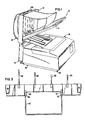
- a paper collection structure is generally illustrated at l0 as comprising a stand body l2 mounted on a leg structure l6 and supporting a paper collection tray l4 for receiving fan-fold paper 20 by way of a first guide 22 and a second guide 24 via the body l2, as the paper 20 is fed from the platen area of the printer l8.
- the printer is shown as comprising a plurality of feet 26 which are conventionally resilient members.
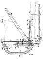
- the leg structure l6 is illustrated as comprising a pair of L-shaped legs 28 and 30 which extend upwardly into the stand body l2 and forwardly beneath the printer l8.
- the legs 28 and 30 are interconnected by way of a bar 38.
- the forward section 32 of the leg 28 extends through an aperture 36 in the bar 38 and is terminated at its distal end with a cap or rubber foot 34 which engages the lower surface of the printer l8.
- the bar may be positioned at any point between a crimp limit 42 and the rubber foot 34 to accommodate various depths of printers.
- a screw 40 may be adjusted in a threaded bore 4l to secure the upper surface 43 of the bar against the lower surface of the printer.
- the upper section 45 of the leg 28 is received in and locked to the body l2.
- the body l2 comprises a generally rectangular structure including a pair of shaped end channels 44, 46, a rear wall 62 with ribs 64, a lower slot 65 for receiving the incoming paper and an upper slot 67 for discharging the paper towards the collection tray l4.
- the upper section 45 of the leg 28 is received through at least one aperture 48 at the slot 65 and at least one aperture 52 in a member 50 spaced above the slot 65.
- These apertures may be in the form of a resulting circular aperture by providing a slot in one member cored from the rear and a slot in the adjacent member cored from the front inasmuch as the base is a molded structure.
- the center of the aperture 52 is preferably aligned with the center of the aperture 48, as each aperture is viewed as a circular aperture.
- a key 54 When the vertical height of the structure is set by moving the base 12 on the legs 28 and 30, a key is inserted into the channel 44, for example, and similarly into the channel 46, to lock the vertical height of the body 12.
- a key 54 comprises an aperture 56 for receiving the leg section 45 therethrough.
- the key 54 has the same general peripheral configuration as the channel 44 (see Fig. 5) and comprises a surface 58 for engaging the inner surface of the channel.
- the key 54 also comprises a handle 60 for moving the key downwardly to lock the body to the leg structure. The locking action is achieved by offsetting the axis of the aperture 56 slightly rearwardly from the centers of the apertures 52 and 48 so that a wedging effect occurs as the key 54 is moved downwardly to wedge between the leg section 45 and the forward inner surface of the channel 44.
- the first paper guide is seen as comprising a lower guide and an upper guide.
- the lower guide is shown as comprising a U-shaped wire, preferably chrome steel, having a first end 66 received in an aperture 68 and a second end 70 received in an aperture 72 of the body 12.
- a downwardly turned forward section 74 may be employed to direct the lower guide somewhat tangentially with respect to the platen.
- the upper guide as best seen in Figs. 2 and 5, comprises a generally rectangular planar body 76 with strengthening ribs 78 and a U-shaped wire form 80, preferably chrome steel, adjustably received through apertures 32 of the member 76.
- the body 12 comprises an aperture 88 for receiving a pivot axle 86 carried by the member 76.
- the upper guide has been shown spaced from the lower guide; however, with the pivot provided at 86, 88, the upper guide is free to ride on the upper surface of the paper 20 during operation.
- the member 76 may be a clear injection molded plastic material.
- the wire form 80 may have a bent section 84 which functions as a skid, particularly with the upwardly pointed hinges of fan-fold paper as the same is discharged from the platen.
- the section 74 of the lower guide will function in the same manner with respect to the downwardly-directed hinges of fan-fold paper.
- the second paper guide is illustrated as comprising a plurality of wire forms 90, 92 which form a channel extending between the lower slot 65 and the upper slot l08.
- wire forms 90 are employed along with three wire forms 92 in an alternate pattern (see FIGS. 4 and 5). Of course, other patterns could be employed.
- the lower slot 65 has a plurality of ribs 69 and 7l extending therethrough to decrease friction and the upper slot l08 has similar ribs ll0, ll2, again to decrease friction.
- the wires 90 have their lower ends received in apertures 94 and their upper ends received in apertures l00 formed in bosses l04, while the wire forms 92 have their lower ends received in apertures 96 and their upper ends received in apertures l02 formed in bosses l06.
- all wires or wire forms which are received in apertures or bores may be provided with rib or serrated end sections as illustrated at 98 for a secure press fit.
- all apertures, recesses forming apertures and other openings and the like may be provided by front and rear coring as mentioned above.
- the paper collection tray l4 is a freely removable and repositionable collection tray and as best seen FIGS. 2 and 4 comprises a floor ll4 extending between a pair of sidewalls ll6 and ll8.
- the collection tray includes a pair of spaced members l20 and l22 extending from an oblique wall l23.
- the wall l23 includes a projection l24 which is received in a respective slot l26 to hold the collection tray in the angled position illustrated in FIG. 2.
- the collection tray is illustrated in the upright or storage position. In this position, the projections l24 are still received in the recesses l26 with the upper portion of the tray located in a transverse recess l30 and secured therein by a latch mechanism l32.
- the latch mechanism l32 is illustrated as comprising a resilient member l33 carrying a lip l34 which yieldably engages and latches behind a lip l36 formed on the wall of the channel 46.
- a similar structure is provided with respect to the channel 44.
- the wall 62 of the body l2 comprises a pair of slots l28 for receiving the members l20 and l22, respectively, when the collection tray l4 is in the upright or storage position.
- the collection tray is shown in the horizontal position in which the projections l24 are now received through slots or recesses l38 to bear against the rear surface of the body l2.
- a member l40 may be provided for each of the channels 44 and 46 and selectively received in slots l38 extending into the channels as limits for the upper ends of the legs 28 and 30.
- This structure would not be as rigid and as stable as that using the keys 54.
Landscapes
- Pile Receivers (AREA)
- Folding Of Thin Sheet-Like Materials, Special Discharging Devices, And Others (AREA)
- Handling Of Continuous Sheets Of Paper (AREA)
Claims (29)
- Vorrichtung zum Sammeln, Falten und Stapeln von fächergefaltetem Papier (20), das kontinuierlich von der Walze eines Druckers (18) geliefert wird, wobei das Papier von der Walze weggeführt wird, um von einer Papiersammeleinrichtung (14) zum Aufnehmen des fächergefalteten Papieres (20) gesammelt zu werden, dadurch gekennzeichnet, daß eine Befestigungseinrichtung (12) die Papiersammeleinrichtung (14) schwenkbar oberhalb und beabstandet von dem Drucker (18) hält, so daß die Papiersammeleinrichtung in einer solchen Stellung einklinken kann, daß es eine deutliche Sicht der Druckfläche des Papieres über der Walze gibt, und wobei eine Führungseinrichtung (22, 24), welche an der Befestigungseinrichtung angebracht ist und sich von einem Aufnahmepunkt benachbart der Walze zu einem Ausgabepunkt (108) oberhalb der Papiersammeleinrichtung (14) zum Aufnehmen und Führen des kontinuierlich geführten Papieres und zum Leiten des Papieres, an dem Ausgabepunkt (108), im wesentlichen horizontal aus der Führungseinrichtung hinaus, so daß das fachergefaltete Papier auf der Papiersammeleinrichtung (14) aufgenommen wird und sich auf der Papiersammeleinrichtung selbst wieder sammelt und stapelt.
- Vorrichtung nach Anspruch 1, dadurch gekennzeichnet, daß die Befestigungseinrichtung einen Körper, welcher erste und zweite Schlitze (65, 108), eine erste Papierführung (22), die mit dem ersten Schlitz (65) in Verbindung ist und ein distales Ende umfaßt, das zum Aufnehmen des Papieres (20) von der Walze positioniert ist, und eine zweite Papierführung (24), die mit dem ersten und dem Zweiten Schlitz in Verbindung ist, um das Papier aus dem ersten Schlitz (65) aufzunehmen und das Papier zu dem zweiten Schlitz (108) zu führen, aufweist, wobei der zweite Schlitz zum Leiten des Papieres auf die Papiersammeleinrichtung (14) positioniert ist.
- Vorrichtung nach Anspruch 1, dadurch gekennzeichnet, daß die Führungseinrichtung ein erstes Kanalmittel (66, 70, 74, 76, 78, 80), das auf dem Körper angebracht ist und sich von diesem zu einem Punkt benachbart der Walze erstreckt und einen ersten Papierkanal zum Aufnehmen des ausgelassenen Papieres definiert, und ein zweites Kanalmittel (90, 92), welches wenigstens einen Durchlaß durch den Körper umfaßt und einen zweiten Papierkanal definiert, der mit dem ersten Papierkanal und dem Ausgabepunkt oberhalb des Papiersammelkorbes in Verbindung ist, aufweist, wobei das Papier, an dem Ausgabepunkt, im wesentlichen horizontal aus dem zweiten Papierkanal läuft, so daß das fächergefaltete Papier auf dem Korb aufgenommen wird und sich selbst auf dem Korb wieder faltet und stapelt.
- Vorrichtung nach Anspruch 3, gekennzeichnet durch ein Schenkelmittel (16), das auf einem Träger benachbart dem Drucker (18) getragen ist, und einen Körper (12), der auf den Schenkelmitteln (16) angebracht ist.
- Vorrichtung nach Anspruch 4, dadurch gekennzeichnet, daß das Schenkelmittel ein Paar Schenkel (28, 30) aufweist, wobei jeder einen mit einer Basis verbundenen oberen Abschnitt und einen unteren Abschnitt zum Eingriff mit dem Träger umfaßt.
- Vorrichtung nach Anspruch 5, dadurch gekennzeichnet, daß das Schenkelmittel weiterhin einen Stab (38), der sich zwischen den Schenkeln erstreckt und diese verbindet, und ein Paar Füße (34) aufweist, die einstellbar an dem Stab befestigt sind, um auf dem Träger zu ruhen und den Eingriff des Stabes mit einer unteren Fläche des Druckes (18) zu bewirken.
- Vorrichtung nach Anspruch 5, dadurch gekennzeichnet, daß das Schenkelmittel einen Stab (38), der sich zwischen den Beinen (28, 30) erstreckt, und ein Paar Schenkel aufweist, die freigebbar mit dem Körper verbindbar und schwenkbar mit dem Stab verbunden sind.
- Vorrichtung nach Anspruch 7, dadurch gekennzeichnet, daß jeder der Schenkel ein distales Ende hat, das zum Eingriff mit der unteren Fläche des Druckers angeordnet ist.
- Vorrichtung nach einem der Ansprüche 4 bis 8, dadurch gekennzeichnet, daß der Körper erste Schlitzmittel, die einen ersten Schlitz in Verbindung mit dem ersten Kanalmittel definieren, und zweite Schlitzmittel, die einen zweiten Schlitz als Teil des zweiten Kanalmittels definieren, aufweist, wobei der zweite Schlitz sich an dem Punkt oberhalb des Papiersammelkorbes öffnet.
- Vorrichtung nach einem der Ansprüche 4 bis 9, dadurch gekennzeichnet, daß das erste Kanalmittel eine erste Papierführung (66, 70, 74), welche sich von dem Körper zu einem Punkt benachbart der Walze erstreckt, um das fächergefaltete Papier darüber aufzunehmen, und eine zweite Papierführung (76, 78, 80), welche sich von dem Körper entlang der ersten Führung zum Aufnehmen des fächergefalteten Papieres darunter erstreckt, aufweist.
- Vorrichtung nach Anspruch 10, dadurch gekennzeichnet, daß jede der ersten und zweiten Führungen ein distales Ende hat, das sich unter einem Winkel weg von der anderen Führung erstreckt.
- Vorrichtung nach Anspruch 10 oder 11, dadurch gekennzeichnet, daß die zweite Papierführung schwenkbar mit dem Körper verbunden ist (86, 88), um oben auf dem fächergefalteten Papier zu ruhen.
- Vorrichtung nach einem der Ansprüche 4 bis 12, dadurch gekennzeichnet, daß das zweite Kanalmittel erst Schlitzmittel, welche einen ersten Schlitz durch den Körper in Verbindung mit dem ersten Kanalmittel definieren, zweite Schlitzmittel, die einen zweiten Schlitz durch den Körper definieren, und Kanalmittel, die mit dem Körper verbunden sind und einen Papierführungskanal zwischen dem ersten und dem zweiten Schlitz definieren, aufweist.
- Vorrichtung nach einem der Ansprüche 4 bis 13, dadurch gekennzeichnet, daß der Papierkorb (14) einen Boden (114), eine Endwand (123), die sich von dem Boden erstreckt, und einen Vorsprung (124), der sich von der Endwand erstreckt, ausweist und der Körper eine Öffnung (126) zum Aufnehmen des Vorsprunges an einer Stelle, an der der Boden (114) sich unter einem nach oben weisenden Winkel, in bezug auf die Horizontale, über den Drucker erstreckt, aufweist.
- Vorrichtung nach einem der Ansprüche 4 bis 13, dadurch gekennzeichnet, daß der Papierkorb (14) einen Boden (114), eine Endwand (123), die sich von dem Boden erstreckt, und ein Vorsprung (124), der sich von der Endwand erstreckt, aufweist und der Körper eine Öffnung (126) zum Aufnehmen des Vorsprunges an einer Stelle, an der der Boden (114) sich horizontal über dem Drucker erstreckt, aufweist.
- Vorrichtung nach einem der Ansprüche 4 bis 13, dadurch gekennzeichnet, daß der Papierkorb (14) einen Boden (114), eine Endwand (123), die sich von dem Boden erstreckt, und einen Vorsprung (124), der sich von der Endwand erstreckt, aufweist und der Körper eine Öffnung (126) zum Aufnehmen des Vorsprunges an einer Stelle, an der sich der Boden (114) vertikal in bezug auf den Drucker erstreckt, aufweist.
- Vorrichtung nach Anspruch 16, gekennzeichnet durch ein Klinkenmittel (132), welche erste und zweite Klinkenelemente umfassen, die jeweils von dem Papiersammelkorb (114) und durch den Körper (12) getragen sind, um freigebbar den Papiersammelkorb (14) in einer vertikalen Position einzuklinken.
- Vorrichtung nach Anspruch 17, dadurch gekennzeichnet, daß das Klinkenmittel ein federdes Hakenmittel (113, 134) auf dem Korb und ein Hakenmittel (136) auf dem Körper, das freigebbar von dem federnden Hakenmittel (133, 134) gegriffen wird, aufweist.
- Vorrichtung nach einem der Ansprüche 4 bis 18, dadurch gekennzeichnet, daß das zweite Kanalmittel erste und zweite Vielzahlen von im allgemeinen U-förmigen Drähten (90, 92) aufweist, die mit dem Körper, beabstandet von dem zweiten Papierkanal und wenigstens einen Abschnitt desselben definierend, verbunden sind.
- Vorrichtung nach Anspruch 14, dadurch gekennzeichnet, daß das Schenkelmittel eine Stange und weiterhin ein Verbindungsmittel, das die Stange mit dem Körper verbindet, aufweist.
- Vorrichtung nach Anspruch 20, dadurch gekennzeichnet, daß das Verbindungsmittel wenigstens eine Öffnung in dem Körper zum gleitbaren Aufnehmen der Stange durch diese und ein Befestigungsmittel zum Befestigen des Körpers in einer vorbestimmten Höhe in bezug auf die Stange aufweist.
- Vorrichtung nach Anspruch 21, dadurch gekennzeichnet, daß das Befestigungsmittel eine Vielzahl vertikal beabstandeter Schlitze (138) in dem Körper und einen Schlüssel (54) zur wahlweisen Anordnung in einem der Schlitze für den Eingriff des distalen Endes der Stange aufweist.
- Vorrichtung nach Anspruch 21, dadurch gekennzeichnet, daß das Befestigungsmittel Kanalmittel, welche einen vertikalen Hohlkanal in dem Körper mit einer ersten Oberfläche definieren, Öffnungsmittel, welche eine Öffnung in dem Körper zum Aufnehmen der Stange durch diese einschließlich einer vorbestimmten Mittelachse definieren, und einen Schlüssel, welcher eine Öffnung zum Aufnehmen der Stange durch diese, eine zweite Oberfläche zum gleitenden Eingriff der ersten Oberfläche und eine Achse, die von der Öffnung von der Mittelachse versetzt ist, um einen Klemmeffekt der ersten und zweiten Oberfläche zu schaffen, um die Stange gegen die Kanten der Öffnungen zu sperren, umfaßt, aufweist.
- Vorrichtung nach Anspruch 1, dadurch gekennzeichnet, daß die Befestigungseinrichtung, welche den Papiersammelkorb über der Oberseite des Druckers (18) und beabstandet von dem Drucker anbringt, Klinkenmittel aufweist, so daß der Korb wahlweise in einer ersten Position, so daß es eine deutliche Sicht der Druckfläche des Papieres über der Walze gibt, und in einer zweiten vertikalen Position für die Lagerung außerhalb des Weges eingeklinkt werden kann.
- Vorrichtung nach Anspruch 24, dadurch gekennzeichnet daß das Führungsmittel eine erste Papierführung (22) und eine zweite Papierführung (24), die mit der ersten Papierführung in Verbindung ist, aufweist, wobei die erste Papierführung sich zu einem Punkt benachbart der Walze erstreckt, um das kontinuierlich zugeführte Papier über sie aufzunehmen, und wobei die zweite Papierführung sich von der ersten Papierführung zu dem Ausgabepunkt oberhalb des Papiersammelkorbes (14) erstreckt, um das kontinuierlich zugeführte Papier von der ersten Papierführung aufzunehmen und auf den Papiersammelkorb zu leiten.
- Vorrichtung nach Anspruch 24 oder 25, dadurch gekennzeichnet, daß das Führungsmittel Mittel, die einen Papierlaufweg definieren, der sich zunächst rückwärts, dann aufwärts und dann vorwärts in bezug auf den Drucker erstreckt, aufweist.
- Vorrichtung nach Anspruch 21, dadurch gekennzeichnet, daß das Führungsmittel Mittel, die weiterhin den Lauf des Papieres in einen Kanal entlang eines Weges definieren, der sich in einer Schleife oberhalb des Druckers erstreckt, aufweist.
- Vorrichtung nach Anspruch 27, dadurch gekennzeichnet, daß das Führungsmittel einen im wesentlichen sich vertikal erstreckenden Körper mit einer Vorderseite, einer Rückseite, einer Oberseite und einer Unterseite, wobei erste und zweite Schlitze (108, 65) sich durch den Körper benachbart der Oberseite bzw. der Unterseite erstrecken, wobei jeder der Schlitze einen jeweiligen Teil des Papierlaufkanales bildet, und Rippen (67, 71, 110, 112) in den Schlitzen, die sich in Richtung des Papierlaufes erstrecken, aufweist.
- Vorrichtung nach Anspruch 27, dadurch gekennzeichnet, daß das Führungsmittel eine Vielzahl von ersten beabstandeten U-förmigen Drähten (90), die obere Enden, welche mit der Rückseite des Körpers oberhalb des ersten Schlitzes (108) verbunden sind, und untere Enden, die mit der Rückseite des Körpers unterhalb des zweiten Schlitzes (65) verbunden sind, umfassen, und eine Vielzahl von zweiten beabstandeten U-förmigen Drähten (91), welche obere Enden, die mit der Rückseite des Körpers unterhalb des ersten Schlitzes (108) verbunden sind, und untere Enden, die mit der Rückseite des Körpers oberhalb des zweiten Schlitzes (65) verbunden sind, umfassen aufweist, wobei die ersten und zweiten Drähte voneinander beabstandet sind, um einen Abschnitt des Laufkanales zu bilden.
Priority Applications (1)
| Application Number | Priority Date | Filing Date | Title |
|---|---|---|---|
| AT86309884T ATE73709T1 (de) | 1985-12-26 | 1986-12-18 | Auffangbehaelter fuer faechergefaltete bahnen in einem drucker. |
Applications Claiming Priority (2)
| Application Number | Priority Date | Filing Date | Title |
|---|---|---|---|
| US81358185A | 1985-12-26 | 1985-12-26 | |
| US813581 | 1991-12-24 |
Publications (3)
| Publication Number | Publication Date |
|---|---|
| EP0230758A2 EP0230758A2 (de) | 1987-08-05 |
| EP0230758A3 EP0230758A3 (en) | 1988-09-07 |
| EP0230758B1 true EP0230758B1 (de) | 1992-03-18 |
Family
ID=25212813
Family Applications (1)
| Application Number | Title | Priority Date | Filing Date |
|---|---|---|---|
| EP86309884A Expired - Lifetime EP0230758B1 (de) | 1985-12-26 | 1986-12-18 | Auffangbehälter für fächergefaltete Bahnen in einem Drucker |
Country Status (4)
| Country | Link |
|---|---|
| EP (1) | EP0230758B1 (de) |
| AT (1) | ATE73709T1 (de) |
| CA (1) | CA1285007C (de) |
| DE (1) | DE3684447D1 (de) |
Cited By (1)
| Publication number | Priority date | Publication date | Assignee | Title |
|---|---|---|---|---|
| USD344751S (en) | 1990-03-29 | 1994-03-01 | Artwright Marketing SDN. BHD. | Paper hopper |
Families Citing this family (4)
| Publication number | Priority date | Publication date | Assignee | Title |
|---|---|---|---|---|
| US4923188A (en) * | 1988-10-26 | 1990-05-08 | Spectra-Physics | Z-fold paper sheet carrier |
| FR2706361A1 (fr) * | 1993-06-10 | 1994-12-23 | Caderas Jean Francois | Structure métallique adaptable aux matériels informatiques et bureautiques, et destinée à recevoir des corbeilles à courrier. |
| DE4332575A1 (de) * | 1993-09-24 | 1995-03-30 | Esselte Meto Int Gmbh | Druckmaschine |
| JP2008055765A (ja) * | 2006-08-31 | 2008-03-13 | Seiko Instruments Inc | 用紙保持構造および電子投票装置用プリンタ |
Family Cites Families (6)
| Publication number | Priority date | Publication date | Assignee | Title |
|---|---|---|---|---|
| BE463551A (de) * | 1944-01-12 | |||
| FR1078477A (fr) * | 1952-02-29 | 1954-11-18 | Carter Davis Ltd | Dispositif permettant l'utilisation de bandes de papier continues sur les machines à écrire |
| GB2093432B (en) * | 1980-12-12 | 1984-04-26 | Spinks James & Sons Ltd | Container for collecting tape |
| EP0150902A1 (de) * | 1984-01-09 | 1985-08-07 | Hudo, Inc. | Apparat zum erneuten Falten von Endlospapier |
| US4515490A (en) * | 1984-01-27 | 1985-05-07 | Marker Iii Franklin | Computer printer stand with multiple paper web guide slots |
| US4541749A (en) * | 1984-04-30 | 1985-09-17 | Mccoy John B | Paper tray and folder |
-
1986
- 1986-12-18 AT AT86309884T patent/ATE73709T1/de not_active IP Right Cessation
- 1986-12-18 EP EP86309884A patent/EP0230758B1/de not_active Expired - Lifetime
- 1986-12-18 DE DE8686309884T patent/DE3684447D1/de not_active Expired - Fee Related
- 1986-12-23 CA CA000526164A patent/CA1285007C/en not_active Expired - Fee Related
Cited By (1)
| Publication number | Priority date | Publication date | Assignee | Title |
|---|---|---|---|---|
| USD344751S (en) | 1990-03-29 | 1994-03-01 | Artwright Marketing SDN. BHD. | Paper hopper |
Also Published As
| Publication number | Publication date |
|---|---|
| EP0230758A3 (en) | 1988-09-07 |
| EP0230758A2 (de) | 1987-08-05 |
| DE3684447D1 (de) | 1992-04-23 |
| ATE73709T1 (de) | 1992-04-15 |
| CA1285007C (en) | 1991-06-18 |
Similar Documents
| Publication | Publication Date | Title |
|---|---|---|
| US4773781A (en) | Fan-fold paper catcher for a printer | |
| DE69509179T2 (de) | Tintengewichtsdetektoranordnung für Farbstrahldrucker | |
| EP0526062B1 (de) | Tintenstrahlschreibewagen | |
| US6568865B1 (en) | Ejected paper receiving unit for large printer and large printer equipped with the same | |
| DE60309544T2 (de) | Druckeinrichtung | |
| EP0230758B1 (de) | Auffangbehälter für fächergefaltete Bahnen in einem Drucker | |
| US6092941A (en) | Printer with a manually operable print head that is detachable from the main printer body | |
| US4749295A (en) | Fan-fold paper catcher for a printer | |
| EP0722836A3 (de) | Tintenstrahlgerät | |
| JPH02212179A (ja) | Z折曲用紙キャリア | |
| EP1219455B1 (de) | Aufzeichnungsgerät mit wölbendem Teil | |
| US4696591A (en) | Fan folded printer output collector | |
| US6840617B2 (en) | Mid-frame for an imaging apparatus | |
| EP0987115A2 (de) | Drucker mit zwei Betriebspositionen | |
| US5806842A (en) | Output paper sheet finishing module and method of using same | |
| US5967682A (en) | Recorder | |
| GB2238998A (en) | Printing press feeder suction head | |
| EP0787593B1 (de) | Tintenstrahldrucker | |
| GB2142879A (en) | Paper guide adapted for use in apparatus for producing a record | |
| US4722506A (en) | Printer stand | |
| US4717273A (en) | Multiple paper holder and method for a computer printer | |
| JP4604350B2 (ja) | 記録媒体の受け装置及びその受け装置を備えたプリンタ | |
| KR0126866Y1 (ko) | 잉크제트 프린터의 헤드보관용기 | |
| ATE138042T1 (de) | Blattfördervorrichtung | |
| US7281870B2 (en) | Ink jet recording apparatus |
Legal Events
| Date | Code | Title | Description |
|---|---|---|---|
| PUAI | Public reference made under article 153(3) epc to a published international application that has entered the european phase |
Free format text: ORIGINAL CODE: 0009012 |
|
| AK | Designated contracting states |
Kind code of ref document: A2 Designated state(s): AT BE CH DE ES FR GB GR IT LI LU NL SE |
|
| PUAL | Search report despatched |
Free format text: ORIGINAL CODE: 0009013 |
|
| AK | Designated contracting states |
Kind code of ref document: A3 Designated state(s): AT BE CH DE ES FR GB GR IT LI LU NL SE |
|
| 17P | Request for examination filed |
Effective date: 19890213 |
|
| 17Q | First examination report despatched |
Effective date: 19900618 |
|
| GRAA | (expected) grant |
Free format text: ORIGINAL CODE: 0009210 |
|
| AK | Designated contracting states |
Kind code of ref document: B1 Designated state(s): AT BE CH DE ES FR GB GR IT LI LU NL SE |
|
| PG25 | Lapsed in a contracting state [announced via postgrant information from national office to epo] |
Ref country code: IT Free format text: LAPSE BECAUSE OF FAILURE TO SUBMIT A TRANSLATION OF THE DESCRIPTION OR TO PAY THE FEE WITHIN THE PRE;WARNING: LAPSES OF ITALIAN PATENTS WITH EFFECTIVE DATE BEFORE 2007 MAY HAVE OCCURRED AT ANY TIME BEFORE 2007. THE CORRECT EFFECTIVE DATE MAY BE DIFFERENT FROM THE ONE RECORDED.SCRIBED TIME-LIMIT Effective date: 19920318 Ref country code: GR Free format text: LAPSE BECAUSE OF FAILURE TO SUBMIT A TRANSLATION OF THE DESCRIPTION OR TO PAY THE FEE WITHIN THE PRESCRIBED TIME-LIMIT Effective date: 19920318 Ref country code: AT Effective date: 19920318 Ref country code: SE Effective date: 19920318 Ref country code: NL Effective date: 19920318 |
|
| REF | Corresponds to: |
Ref document number: 73709 Country of ref document: AT Date of ref document: 19920415 Kind code of ref document: T |
|
| REF | Corresponds to: |
Ref document number: 3684447 Country of ref document: DE Date of ref document: 19920423 |
|
| ET | Fr: translation filed | ||
| PG25 | Lapsed in a contracting state [announced via postgrant information from national office to epo] |
Ref country code: ES Free format text: LAPSE BECAUSE OF FAILURE TO SUBMIT A TRANSLATION OF THE DESCRIPTION OR TO PAY THE FEE WITHIN THE PRESCRIBED TIME-LIMIT Effective date: 19920629 |
|
| NLV1 | Nl: lapsed or annulled due to failure to fulfill the requirements of art. 29p and 29m of the patents act | ||
| PLBE | No opposition filed within time limit |
Free format text: ORIGINAL CODE: 0009261 |
|
| STAA | Information on the status of an ep patent application or granted ep patent |
Free format text: STATUS: NO OPPOSITION FILED WITHIN TIME LIMIT |
|
| 26N | No opposition filed | ||
| PGFP | Annual fee paid to national office [announced via postgrant information from national office to epo] |
Ref country code: LU Payment date: 19931116 Year of fee payment: 8 |
|
| PGFP | Annual fee paid to national office [announced via postgrant information from national office to epo] |
Ref country code: BE Payment date: 19931117 Year of fee payment: 8 |
|
| PGFP | Annual fee paid to national office [announced via postgrant information from national office to epo] |
Ref country code: DE Payment date: 19931123 Year of fee payment: 8 |
|
| PGFP | Annual fee paid to national office [announced via postgrant information from national office to epo] |
Ref country code: GB Payment date: 19931129 Year of fee payment: 8 |
|
| PGFP | Annual fee paid to national office [announced via postgrant information from national office to epo] |
Ref country code: FR Payment date: 19931217 Year of fee payment: 8 |
|
| PGFP | Annual fee paid to national office [announced via postgrant information from national office to epo] |
Ref country code: CH Payment date: 19931227 Year of fee payment: 8 |
|
| EPTA | Lu: last paid annual fee | ||
| PG25 | Lapsed in a contracting state [announced via postgrant information from national office to epo] |
Ref country code: LU Free format text: LAPSE BECAUSE OF NON-PAYMENT OF DUE FEES Effective date: 19941218 Ref country code: GB Effective date: 19941218 |
|
| PG25 | Lapsed in a contracting state [announced via postgrant information from national office to epo] |
Ref country code: LI Effective date: 19941231 Ref country code: CH Effective date: 19941231 Ref country code: BE Effective date: 19941231 |
|
| BERE | Be: lapsed |
Owner name: BANKIER COMPANIES INC. Effective date: 19941231 |
|
| GBPC | Gb: european patent ceased through non-payment of renewal fee |
Effective date: 19941218 |
|
| PG25 | Lapsed in a contracting state [announced via postgrant information from national office to epo] |
Ref country code: FR Effective date: 19950831 |
|
| REG | Reference to a national code |
Ref country code: CH Ref legal event code: PL |
|
| PG25 | Lapsed in a contracting state [announced via postgrant information from national office to epo] |
Ref country code: DE Effective date: 19950901 |
|
| REG | Reference to a national code |
Ref country code: FR Ref legal event code: ST |